Altronix SMP10C12X Series Installation Manual
Hide thumbs
Also See for SMP10C12X Series:
- Installation manual (9 pages) ,
- Installation manual (9 pages)
Table of Contents
Advertisement
Quick Links
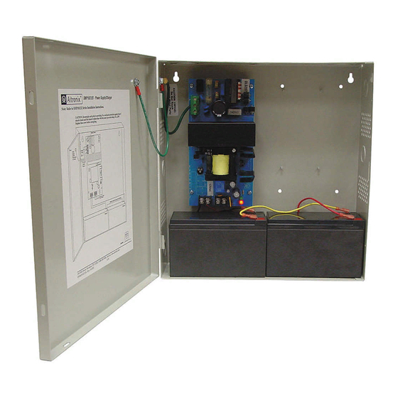
These units convert a 115VAC 50/60Hz input into a regulated 12VDC output at up to 10A continuous supply current
(see specifications).
SMP10C12X Series Power Supply Configuration Reference Chart:
Altronix
Model Number
SMP10C12X
SMP10C12XX*
SMP10PMC12X
SMP10PMC12XX*
SMP10PM12P4
SMP10PM12P4CB
SMP10PM12P8
SMP10PM12P8CB
SMP10PM12P16
SMP10PM12P16CB
*Refer to Enclosure Dimensions on pg.7 for enclosure size.
Battery Backup:
• Built-in charger for sealed lead acid or gel type batteries.
• Maximum charge current 0.7A.
• Automatic switch over to stand-by battery when
AC fails (zero voltage drop).
Features:
• AC input and DC output LED indicators.
• Short circuit and thermal overload protection.
Wiring methods should be in accordance with the National Electrical Code/NFPA 70/NFPA 72/ANSI and with all local
codes and authorities having jurisdiction. Product is intended for indoor use only.
1. Mount unit in the desired location. Mark and predrill holes in the wall to line up with the top two keyholes in the
enclosure. Install two upper fasteners and screws in the wall with the screw heads protruding. Place the enclosure's
upper keyholes over the two upper screws; level and secure. Mark the position of the lower two holes. Remove the
enclosure. Drill the lower holes and install three fasteners. Place the enclosure's upper keyholes over the two
upper screws. Install the two lower screws and make sure to tighten all screws (Enclosure Dimensions, pgs. 6-7).
Secure enclosure to earth ground.
2. Connect AC power to the terminals marked [L & N].
Use 18 AWG or larger for all power connections (Battery, DC output).
3. Measure output voltage before connecting devices. This helps avoiding potential damage.
Keep power-limited wiring separate from non power-limited wiring (115VAC, 50/60Hz Input, Battery Wires).
Minimum 0.25" spacing must be provided.
CAUTION: Do not touch exposed metal parts. Shut branch circuit power before installing or servicing equipment.
There are no user serviceable parts inside. Refer installation and servicing to qualified service personnel.
SMP10C12Xseries
SMP10C12X Series Installation Guide
Accessory
Power
Number
Distribution
of
Module(s)
Outputs
-
1
PD4
4
PD4CB
PD8
8
PD8CB
PD16W
16
PD16WCB
Installation Instructions:
Overview:
Fused
PTC Outputs
Outputs
(auto-resettable)
-
-
-
-
-
-
-
-
-
P
-
P
-
P
-
P
-
P
-
P
Specifications:
Features (cont'd):
• Complete with power supply, power distribution module
(when applicable), enclosure, cam lock, and battery leads.
• Power ON/OFF switch.
Supervised models only:
• AC fail supervision (form "C" contacts).
• Battery presence and low battery supervision
(form "C" contacts).
Individual
Output
Rating (A)
Supervised
-
10A
3.5A
2.5A
P
3.5A
2.5A
3.5A
2.5A
115VAC
12VDC
50/60Hz
Total
Input
Output
Current
Current
(A)
(A)
1.45A
10A
- 1 -
Advertisement
Table of Contents

Related Manuals for Altronix SMP10C12X Series


Summary of Contents for Altronix SMP10C12X Series
-
Page 1: Specifications
SMP10C12X Series Installation Guide Overview: These units convert a 115VAC 50/60Hz input into a regulated 12VDC output at up to 10A continuous supply current (see specifications). SMP10C12X Series Power Supply Configuration Reference Chart: 115VAC 12VDC Accessory 50/60Hz Total Power Number... - Page 2 4. Connect devices to be powered: a. For Power Supply Board connect to the terminals marked [– DC +]. b. For Power Distribution Module(s) connect devices to be powered to the terminal pairs 1 to 4 marked [1P & 1N through 4P & 4N] (Fig. 3, pg. 4) 1 to 8 marked [1P & 1N through 8P & 8N] (Fig. 4, pg. 4) or 1 to 16 marked [1P &...
-
Page 3: Power Supply
Fig. 2 CAUTION: De-energize unit prior to servicing. For continued protection against fire hazard replace fuse with the same type and rating, 15A, 32V. Power Supply Board AC DC C NO NC C 5A 250V --- BAT + --- DC + 115 power mains Earth Ground Wire Strap... - Page 4 Power Distribution Module(s): Fig. 3 Fig. 4 Used 1P, 2P, 3P, 4P = FUSED OUTPUTS Used 1N, 2N, 3N, 4N = COMMON OUTPUTS on PTC on PTC POWER DISTRIBUTING UNIT Models Models F U S E D P O W E R O U T P U T S INPUT INPUT...
- Page 5 Terminal Identification: Power Supply Board Terminal Legend Function/Description L, G, N Connect 115VAC to these terminals: L to Hot, N to Neutral. – DC + 12VDC @ 10A continuous outputs. *AC FAIL Indicates loss of AC power, e.g. connect to audible device or alarm panel. Relay normally NC, C, NO energized when AC power is present.
- Page 6 Enclosure Dimensions for: SMP10C12X SMP10PMC12X SMP10PM12P4 SMP10PM12P4CB SMP10PM12P8 SMP10PM12P8CB SMP10PM12P16 SMP10PM12P16CB 13.5” x 13” x 3.25” (342.9mm x 330.2mm x 82.55mm) 1.40” 4.85” 4.85” 1.40” (36mm) (123mm) (123mm) (36mm) 1.20” (31mm) 3.25” (83mm) 12.5” (318mm) 1.20” 1.20” 0.75” 0.75” (31mm) 11.0”...
- Page 7 Enclosure Dimensions for: SMP10C12XX SMP10PMC12XX 15.5” x 12” x 4.5” (393.7mm x 304.8mm x 114.3mm) 1.5” 4.615” 4.615” 1.5” (38.1mm) (117.22mm) (117.22mm) (38.1mm) 1.75” (44.45mm) 1.375” (34.925mm) 1.125” (28.575mm) 12.23” 4.5” 4.5” (310.64mm) (114.3mm) (114.3mm) 1.25” 1.1” 1.1” 1.25” (31.75mm) (27.94mm) (27.94mm) (31.75mm)
- Page 8 Notes: Altronix is not responsible for any typographical errors. Product specifications are subject to change without notice. 140 58th Street, Brooklyn, New York 11220 USA | phone: 718-567-8181 | fax: 718-567-9056 web site: www.altronix.com | e-mail: info@altronix.com | Lifetime Warranty | Made in U.S.A.
Need help?
Do you have a question about the SMP10C12X Series and is the answer not in the manual?
Questions and answers