Table of Contents
Advertisement
Advertisement
Table of Contents

Related Manuals for RS PRO LCR 1701


Summary of Contents for RS PRO LCR 1701
- Page 1 Instruction Manual LCR 1701 & LCR 1703 Digital Multimeter ...
-
Page 2: Read First
Safety sheet Warning Warning Safety sheet ........ -
Page 3: Maintenance
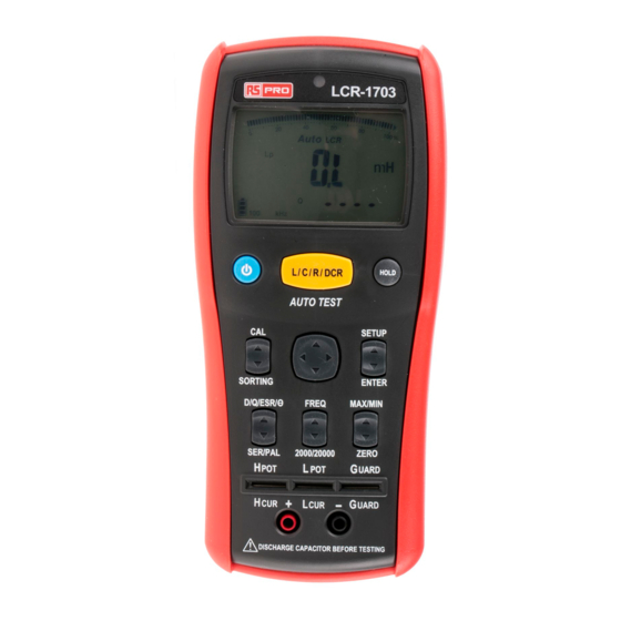
CAUTION ˙ Never connect a source of voltage that could result in damage the meter and the equipment under test. ˙ Do not expose Meter to extremes in temperature or high humidity. Symbols as marked on the Meter and Instruction manual ... - Page 4 The Meter Description Front Panel Illustration 1. LCD display : 20000/2000 counts . 2. Function buttons. 3. 5-Wire input terminal for SMD test probe or DIP part. 4. 2-Wire input terminal for Alligator Clip.
- Page 5 The assembly 1. 5V AC Adapter (only LCR 1703) 2. USB Cable (only LCR 1703) 3. Shorting Bar 4. SMD Test Probe (only LCR 1703) 5. Alligator Clip Set.
- Page 6 Measuring Principle ...
- Page 7 Phase Drawing...
- Page 8 Making 5-wire measuring with the SMD test probe...
- Page 9 Making 4-wire measuring in the 5-wire terminal Making 2-wire measuring with the alligator clip...
- Page 10 Measuring L/C/R/DCR • Press the L/C/R/DCR button to select the measuring function. • Press the L/C/R/DCR button for 2 seconds to enter the Auto L/C/R function.
- Page 11 Measuring D/Q/ESR/ • Press the D/Q/ESR/button to select the measuring function.
- Page 12 Select test Frequency • Press the FREQ button to select the test frequency. • The 100KHz test frequency is only at LCR1703.
- Page 13 Select Series / Parallel measuring function • At the L/C/R measuring function, it defaults to Auto Series / Parallel measuring function. • Press the SER/PAL button to select the measuring function.
- Page 14 Select Display Count • Press the 2000 /20000 button to select the display count. Zero The Zero mode records the current input value as reference and appears on the sub display. The after input values will subtract the reference value and display on the main display. To use the Zero mode, follow the steps below.
-
Page 15: Display Hold
Display Hold • Press the HOLD button to hold the reading of the meter, press the button again to return. Display MAX/MIN The MAX/MIN mode records the maximum and the minimum input values. When the inputs go below the recorded minimum value or above the recorded maximum value, the meter beeps and records the new value. - Page 16 Calibrate In order to achieve the best measuring result, calibration is must. To calibrate the meter, press the CAL button.
- Page 17 When “OPEn” appears on the sub display, make the terminal or the SMD test probe open, and press the CAL button to start open calibration. About 30 seconds later, the result of the open calibration appears on the main display. If the result is pass, press the CAL button to next step.
- Page 18 When “Srt” appears on the sub display, make the terminal or the SMD test probe short, and press the CAL button to start short calibration. About 30 seconds later, the result of the short calibration appears on the main display. If the result is pass, press the CAL button to complete the calibration.
- Page 19 Sorting To check the accuracy of the part, press the SORTING button to enter the sorting mode. The sorting result appears on the main display, and the current value appears on the sub display.
- Page 20 The default sorting standard value is the current value, and the default tolerance is ±1.0%. Setup Sorting Standard To setup the sorting standard value, follow the steps below. 1. Press the SETUP button to enter the setup mode. 2 Press and button to setup the range of the standard value.
-
Page 21: Battery Replacement
Battery Replacement Refer to the following figure to replace the batteries : Caution ˙ Replace the batteries as soon as the low batteries indicator appears, to avoid false reading. ˙1.5V x 4 alkaline batteries. External Power Source To save the batteries power by using the external power source. ... -
Page 22: Specifications
Specifications General Specifications Maximum voltage applied to any terminal : or 30V Display : 2000/20000 counts Overrange Indication : OL Batteries Life : 50 hours " is displayed when the batteries Low Batteries Indication :" voltage drops beow operating voltage. Low battery voltage : Approx. -
Page 23: Electrical Specifications
Electrical Specifications (1) Test Frequency : Range Resolution Accuracy 100.00 Hz 0.01 Hz ± 0.01% 120.00 Hz 0.01 Hz ± 0.01% 1.0000 kHz 0.1 Hz ± 0.01% 10.000 kHz 1 Hz ± 0.01% 100.00 kHz 10 Hz ± 0.01% (2) Test Signal : AC Signal Level : 600mVrms AC Signal Accuracy : ±10% DC Bias Level : 1V... - Page 24 (4) Inductance Frequency Range Accuracy 20.000mH ± (0.5% + 5d) 200.00mH 2000.0mH ± (0.2% + 5d) 100Hz 20.000H 120Hz 200.00H 2000.0H ± (0.5% + 5d) 20.000KH ± (1.0% + 5d) 2000.0uH ± (0.5% + 5d) 20.000mH 200.00mH ± (0.2% + 5d) 1KHz 2000.0mH 20.000H...
- Page 25 (5) Capacitance Frequency Range Accuracy 2000.0pF ± (0.5% + 5d) 20.000nF 200.00nF ± (0.2% + 5d) 2000.0nF 100Hz 120Hz 20.000uF 200.00uF ± (0.5% + 5d) 2000.0uF ± (1.0% + 5d) 20.000mF ± (2.0% + 5d) 2000.0pF ± (0.5% + 5d) 20.000nF 200.00nF ±...
- Page 26 (6) Resistance Frequency Range Accuracy 200.00Ω 2.0000KΩ ± (0.2% + 5d) 20.000KΩ 100Hz 200.00KΩ 120Hz 2.0000MΩ 20.000MΩ ± (0.5% + 5d) 200.00MΩ ± (1.0% + 5d) 20.000Ω ± (0.5% + 15d) 200.00Ω 2.0000KΩ 20.000KΩ ± (0.2% + 5d) 1KHz 200.00KΩ 2.0000MΩ...
- Page 27 (7) DCR Range Resolution Accuracy 200.00Ω 0.01Ω 2.0000KΩ 0.0001KΩ 20.000KΩ 0.001KΩ ± (0.2% + 5d) 200.00KΩ 0.01KΩ 2.0000MΩ 0.0001MΩ 20.000MΩ 0.001MΩ ± (0.5% + 5d) 200.00MΩ 0.01MΩ ± (1.0% + 5d) [1] < 50dgt rolling. Input Protection : 30V or 30V Minimum Resolution :...
-
Page 28: Limited Warranty
Limited Warranty This meter is warranted to the original purchaser against defects in material and workmanship for 3 years from the date of purchase. During this warranty period, RS Components will, at its option, replace or repair the defective unit, subject to verification of the defect or malfunction. - Page 29 Africa RS Components SA P.O. Box 12182, Vorna Valley, 1686 20 Indianapolis Street, Kyalami Business Park, Kyalami, Midrand South Africa www.rs-components.com Asia RS Components Pte Ltd. 31 Tech Park Crescent Singapore 638040 www.rs-components.com China RS Components Ltd. Suite 23 A-C East Sea Business Centre Phase 2 No.
Need help?
Do you have a question about the LCR 1701 and is the answer not in the manual?
Questions and answers