Table of Contents
Advertisement
Quick Links
Advertisement
Table of Contents

Subscribe to Our Youtube Channel
Related Manuals for RS PRO IDM 71


Summary of Contents for RS PRO IDM 71
- Page 1 INSTRUCTION MANUAL IDM 71/72/73 DIGITAL MULTIMETER ...
-
Page 2: Safety Alert Symbol
Safety Alert Symbol : READ and UNDERSTAND all W arning Caution ....safety alert symbols : in this manual. . -
Page 3: Table Of Contents
Table of Contents Title Page SAFETY “Warning” and “Caution”Alert Symbol Statements Warning and Cautions Symbols as Marked on The Meter Symbols and Terms in The Manual Safety Compliance And Certification Safety Compliance Safety Certification Introduction Unpacking and Inspection Environmental Conditions Meter Description Making Basic Measurements Preparation and Caution Before Measurement... -
Page 4: Safety
Safety Safety Warning Caution Alert Symbol Statement : " " " " " Warning" Alert Symbol A "Warning" Statement identifies hazardous conditions and actions that could cause BODILY HARM or DEATH. " Caution" Alert Symbol A " Caution" Statement: identifies conditions and actions that could DAMAGE the meter or the equipment under test. -
Page 5: Symbols As Marked On The Meter
Safety ˙ To avoid false readings that can lead to electric shock and injury, replace battery as soon as low battery indicator appears. ˙ Disconnect circuit power and discharge all high-voltage capacitors before testing resistance, continuity, diodes, or capacitance. ˙ Do not use the meter around explosive gas or vapor. ˙... -
Page 6: Symbols And Terms In The Manual
Safety Symbols and Terms in The Manual Symbols : Caution, Risk of Danger. Warning : Identifies hazardous conditions and actions that could cause BODILY HARM or DEATH Caution Identifies conditions and actions that could DAMAGE the meter or equipment under test. Fuse. -
Page 7: Safety Compliance And Certification
Safety Compliance And Certification POLLUTION DEGREE 1 No POLLUTION or only dry, non-conductive POLLUTION occurs. The POLLUTION has no influence. POLLUTION DEGREE 2 Normal POLLUTION only non-conductive POLLUTION occurs. Occasionally, however, a temporary conductivity caused by condensation must be expected. POLLUTION DEGREE 3 Conductive POLLUTION occurs, or dry, non-conductive POLLUTION occurs which becomes conductive due to condensation, which is expected. -
Page 8: Introduction
IEC 61010-(2001), EN61010 (2001), UL3111-1(6.1994), CSA C22.2 NO.1010-1-92 to terminals: V/Ω/µA IDM 71,72 and 73 : Cat. Ⅳ 600 Volts. A IDM 72 and 73 only : Cat. Ⅳ 600 Volts. 7. Shock Vibration : Sinusoidal vibration per Mil-T-28800E (5 ~55 Hz, 3g maximum). -
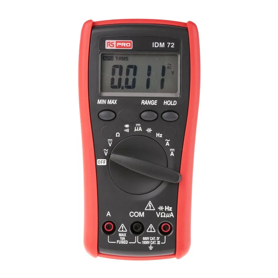
Page 9: Meter Description
5. Input terminal for all functions EXCEPT current (A) functions. 6. Common (Ground reference) input terminal for all functions. Display Features Functions & Power On/Off A Input (Not IDM 71) Input COMMON Input Making Basic Measurements Preparation and Caution Before Measurement : Observe the rules of Warnings ... -
Page 10: Measuring Ac/Dc Voltage And Frequency
Making Basic Measurements Measuring AC/DC Voltage And Frequency The non-zero display reading is normal when the meter test leads are open, but this will not affect actural measurement accuracy. The meter will show zero or close to zero when the test leads are shorted. In reading AC voltage or current, reading-settling time increases to several seconds at the low end of AC voltage and current ranges in rms models. -
Page 11: Measuring Dc Μa And Ac / Dc A Current
UNKNOWN MEASUREMENT TEST LEAD Measuring DC µA, DC A, AC A Current (Not IDM 71) Warning Never attempt an in–circuit measurement where the open–circuit potential to earth potential is greater than 500V for example a 3-phase system measurement; you may damage the meter or be injured. - Page 12 Making Basic Measurements Caution To avoid possible damage to the meter or to the equipment under test, check the meter’s fuses before measuring current. Use the proper terminals, function, and range for your measurement. Never place the probes across (in parallel with) any circuit or component when the leads are plugged into the current terminals When measuring current, the meter acts like an impedance such as 0.01Ω...
-
Page 13: Measuring Capacitance
Making Basic Measurements Measuring Capacitance Caution To avoid possible damage to the meter or to the equipment under test, disconnect circuit power and discharge all high-voltage capacitors before measuring capacitance. Use the DC voltage function to confirm that the capacitor is discharged. -
Page 14: Testing Diodes And Continuity
Making Basic Measurements Testing Diodes and Continuity Diode : Good ! Good ! Bad ! Continuity : Caution For in-circuit test, turn circuit power off and discharge all high-voltage capacitors through an appropriate resistance load. Note – Use the diode test to check if the semiconductor junction is good or bad. The meter sends a current through the semiconductor junction to measure the voltage drop across the junction. -
Page 15: Features Description
Features Features Feature Description The meter has the following features : Display Hold – Freezes the display. Min Max Hold – Record the Max or Min reading of the display. Range – Selects the manual ranging mode. The default mode is Automatic Range. –... -
Page 16: Using The Features
Using The Features Using The Features Manual Ranging and Auto Ranging Note - The Range button is pressed to select manual ranging and to change ranges. When the Range button is pressed once, the indicator turns off. AUTO Press the Range button to select the appropriate range for the measurement you want to make. -
Page 17: Display Hold
Using The Features RS232 (IDM 73 only) Display Hold Note – Press the Hold button to toggle in and out of the display Hold mode. The MAX / MIN feature is unavailable when display Hold is active. Backlight Note Press Backlight –... -
Page 18: Auto Power Off (Battery Saver)
Using The Features Auto Power Off (Battery Saver) Note – If the meter idles for more than 10 minutes, the meter automatically turns the power off. When this happens, the LCD displaying-state of the meter is saved. The meter can be turned back on by pushing any button, the LCD displays the saved state. -
Page 19: Maintenance
If the meter is not to be used for a long period, more than 60 days, remove the battery and store it separately. Fuse Replacement (Not IDM 71) Refer to the following figure to replace fuse : Caution ˙... -
Page 20: Battery Replacement
Review this manual to make sure that you are operating the meter correctly. Testing the Fuse and Test Leads Test the fuse and test leads as shown below Testing the Fuse (Not IDM 71) Testing the Test Leads... -
Page 21: Specification
Specification Specification General Specifications Display : 6000 counts, updates 1.5/sec. Polarity Indication : Automatic, positive implied, negative indicated. Overrange Indication : “OL” or “-OL” Low Battery Indication : “<” is displayed when the battery voltage drops below operating voltage. Auto Power Off : Approx 10 minutes. Operating Ambient : Non-condensing ≦10°C ,11°C ~ 30°C (≦80% R.H) 31°C ~ 40°C (≦75% R.H), 41°C ~ 50°C (≦45% R.H), Storage Temperature : -20°C to 60°C , 0 to 80% R.H. - Page 22 50Hz ~ 500Hz 2V max 10.00A *2 Overload Protection : A input : 10A ,600V, high energy fuse. (Not IDM 71) µA input : 600V rms. * 1 AC Conversion Type : Conversion type and additional specification are same as DC/AC Voltage.
- Page 23 Specification (3) Resistance Overload Range Accuracy protection 600.0Ω *2 6.000KΩ ±(0.7% + 2 dgt) 60.00KΩ 600V rms 600.0KΩ 6.000MΩ ±(1.0% + 2 dgt) 60.00MΩ *1 ±(1.5% + 2 dgt) Open circuit Voltage : -1.3V approx. * 1 < 100 dgt rolling. * 2 <...
- Page 24 Specification (5) Frequency ** Sensitivity Range Accuracy 6000Hz 100mV rms 60.00KHz Frequency : 600.0KHz 0.1%±1digit 6.000MHz 250mV rms 60.00MHz 1V rms Overload Protection : 600V rms. Sensitivity level tested by a square-wave form. * Less than 20Hz, the sensitivity is 1.5V rms. ** Max.Sensitivity : <5 Vac rms.
- Page 25 Africa RS Components SA P.O. Box 12182, Vorna Valley, 1686 20 Indianapolis Street, Kyalami Business Park, Kyalami, Midrand South Africa www.rs-components.com Asia RS Components Pte Ltd. 31 Tech Park Crescent Singapore 638040 www.rs-components.com China RS Components Ltd. Suite 23 A-C , East Sea Business Centre Phase 2 , No.
Need help?
Do you have a question about the IDM 71 and is the answer not in the manual?
Questions and answers