
Related Manuals for Fimap FV10 ECO ENERGY


Summary of Contents for Fimap FV10 ECO ENERGY
- Page 1 USE AND MAINTENANCE MANUAL FV10 ECO ENERGY FV15 ECO ENERGY ED. 06-2014 ORIGINAL INSTRUCTIONS Doc. 10045505 AA Version...
- Page 2 The descriptions contained in this document are not binding. The company therefore reserves the right to make any modifications at any time to elements, details, or accessory supply, as considered necessary for reasons of improvement or manufacturing/commercial requirements. The reproduction, even partial, of the text and drawings contained in this document is prohibited by law. The company reserves the right to make any technical and/or supply modifications.
-
Page 3: Table Of Contents
CONTENTS ON CONSIGNMENT OF THE APPLIANCE ............................3 INTRODUCTORY COMMENT ................................3 INTENDED USE ....................................3 SERIAL NUMBER PLATE ................................. 3 TECHNICAL DESCRIPTION ................................3 SYMBOLS USED ON THE MACHINE ..............................4 GENERAL SAFETY REGULATIONS ..............................5 PREPARATION OF THE APPLIANCE ............................... 6 HANDLING THE PACKED APPLIANCE .............................. -
Page 4: On Consignment Of The Appliance
ON CONSIGNMENT OF THE APPLIANCE SERIAL NUMBER PLATE When the machine is consigned to the customer, an immediate check The serial number plate is located at the rear of the vacuum head, and must be performed to ensure all the material mentioned in the shipping indicates the general characteristics of the appliance, in particular the documents has been received, and also to check the machine has not serial number. -
Page 5: Symbols Used On The Machine
SYMBOLS USED ON THE MACHINE Main switch symbol. Used in the vacuum head to indicate the main switch. Air flow rate regulation lever symbol. Used in the vacuum head to indicate the lever for regulating the air flow rate during the vacuum phase. “OPEN”... -
Page 6: General Safety Regulations
GENERAL SAFETY REGULATIONS The regulations below must be carefully followed in order to avoid harm to the operator and damage to the machine. WARNING: Carefully read the warnings contained in this booklet and take care of it for further consultations. •... -
Page 7: Preparation Of The Appliance
PREPARATION OF THE APPLIANCE 1. HANDLING THE PACKED APPLIANCE The appliance is contained in specific packaging, and since the packaging elements (plastic bags, staples, etc.) are a potential source of danger they should not be left within the reach of children, disabled people, etc. -
Page 8: Components Of The Appliance
PREPARATION OF THE APPLIANCE 3. Insert the appliance into the protective bag, taking care not to damage either during this operation. 4. Insert the appliance into the carton, taking care not to damage either during this operation. Remember to place at the bottom of the carton the block for the wheels of the appliance, position around the collection tank the blocks for preventing damage during transportation. -
Page 9: Components Of The Vacuum Head
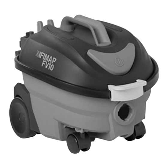
PREPARATION OF THE APPLIANCE 6. COMPONENTS OF THE VACUUM HEAD The components of the vacuum head assembly are as follows: 1. Vacuum cap release lever. 2. Main switch. 3. Handle bar for vacuum head lifting. 4. Lever for noise level and energy saving adjustment (only for FV15). 5. -
Page 10: Inserting Filter - Paper Collection Bag
PREPARATION OF THE APPLIANCE 2. Make sure that the main switch (1) is in the rest position, if not, disable it. 3. Check that the plug (2) on the power cable (3) has been taken out of the socket (4) of the mains supply, and if not, disconnect it. - Page 11 PREPARATION OF THE APPLIANCE 4. Using the handle (4), in the vacuum head assembly, remove the vacuum head assembly from the collection tank (rotating it and shifting it as indicated in the image). 5. Lay the head gently on the floor. 6.
-
Page 12: Preparing To Work
PREPARING TO WORK Before beginning to work, it is necessary to: 1. Before using, the appliance must be in order and safe to use with the work equipment, especially the power cable and the extension cable. If everything is not in order, the appliance must not be used. 2. - Page 13 PREPARING TO WORK 10. Insert the power cable plug (6) into the socket on the vacuum cap. 11. Insert the power cable locking bracket (5). 12. Secure the cable locking bracket by turning the bracket locking lever (4). Page 12...
-
Page 14: Work
WORK To start working, do as follows: 1. Carry out all the checks in the section “PREPARING TO WORK”. 2. Check that the plug (1) on the power cable (2) has been taken out of the socket (3) of the mains supply, and if not, disconnect it. -
Page 15: At The End Of The Work
AT THE END OF THE WORK At the end of work, and before carrying out any type of maintenance, perform the following operations: 1. Do what is required to make sure the machine is in a safe condition (see MACHINE SAFETY’”). -
Page 16: Daily Maintenance
DAILY MAINTENANCE PERFORM ALL MAINTENANCE OPERATIONS IN SEQUENCE 1. EMPTYING THE COLLECTION TANK To empty the collection tank of solid waste, proceed as follows: 1. Take the appliance to the designated place for emptying the collection tank. 2. Do what is required to make sure the machine is in a safe condition (see MACHINE SAFETY’”). -
Page 17: Cleaning Accessories
DAILY MAINTENANCE 2. CLEANING ACCESSORIES Accessories in a good condition guarantee better suction and cleaning of the floor as well as a longer vacuum motor life. To clean the accessories, proceed as follows: 1. Take the machine to the maintenance area. 2. -
Page 18: Weekly Maintenance
WEEKLY MAINTENANCE 1. CLEANING THE COLLECTION TANK Carefully cleaning the collection tank prolongs the life of the appliance. To clean the collection tank, proceed as follows: 1. Take the appliance to its designated maintenance area. 2. Do what is required to make sure the machine is in a safe condition (see MACHINE SAFETY’”). -
Page 19: Cleaning The Vacuum Motor Filter
WEEKLY MAINTENANCE 4. Using the handle (2), in the vacuum head assembly, remove the vacuum head assembly from the collection tank (rotating it and shifting it as indicated in the figure). 5. Remove the fabric filter (3) from the vacuum cap, making sure not to remove the seal. 6. -
Page 20: Cleaning The Exhaust Air Filter
WEEKLY MAINTENANCE To remove the vacuum motor sponge filter, proceed as follows: 6. Remove the motor mesh (4) turning it anti-clockwise. 7. Remove the sponge filter (5). 8. Clean it with detergent and warm water. 9. Repeat the operations in reverse to reassemble. WARNING: Check the state of wear of the vacuum motor filter, if the filter surface area is blocked or has been damaged, replace according to the section “REPLACING THE... - Page 21 WEEKLY MAINTENANCE To remove the vacuum motor sponge filter, proceed as follows: 6. Remove the mesh (4) and the exhaust air filter (5). 7. Clean it with detergent and warm water. 8. Repeat the operations in reverse to reassemble. WARNING: Check the state of wear of the sponge filter, if the filter surface area is blocked or has been damaged, replace according to the section “REPLACING THE EXHAUST AIR...
-
Page 22: Extraordinary Maintenance
EXTRAORDINARY MAINTENANCE 1. REPLACING THE FABRIC FILTER To replace the fabric filter, proceed as follows 1. Take the appliance to its designated maintenance area. 2. Do what is required to make sure the machine is in a safe condition (see MACHINE SAFETY ’”). -
Page 23: Replacing The Exhaust Air Filter
EXTRAORDINARY MAINTENANCE 4. Using the handle (2), in the vacuum head assembly, remove the vacuum head assembly from the collection tank (rotating it and shifting it as indicated in the figure). 5. Remove the fabric filter (3) from the vacuum cap, making sure not to remove the seal. To remove the vacuum motor sponge filter, proceed as follows: 6. -
Page 24: Replacing The Power Cable
EXTRAORDINARY MAINTENANCE 4. Using the handle (2), in the vacuum head assembly, remove the vacuum head assembly from the collection tank (rotating it and shifting it as indicated in the figure). 5. Push down the locking lever (3) of the mesh (4) of the exhaust air filter. To remove the vacuum motor sponge filter, proceed as follows: 6. - Page 25 EXTRAORDINARY MAINTENANCE 4. Remove the power cable locking bracket (2). 5. Remove the damaged power cable (3) and replace it with a new cable. 6. Repeat the operations in reverse to reassemble. Page 24...
-
Page 26: Troubleshooting
TROUBLESHOOTING 1. THE APPLIANCE DOES NOT SWITCH ON If the appliance does not switch on, proceed as follows: 1. Press the main switch (1). 2. Check that the plug (2) on the power cable (3) of the appliance has been correctly inserted into the socket (4) of the mains supply, and if not, properly connect it. -
Page 27: Disposal
DISPOSAL To dispose of the appliance, take it to a demolition centre or an authorised collection centre. Before scrapping the machine it is necessary to remove and separate the following materials and send them to the appropriate collection centres in accordance with the environmental hygiene regulations currently in force: •... -
Page 28: Ec Declaration Of Conformity
Santa Maria di Zevio, 10/04/2014 FIMAP S.p.A. Legal representative Giancarlo Ruffo FIMAP spa Via Invalidi del Lavoro, 1 - 37050 S.Maria di Zevio (Verona) Italy www.fimap.com Tel. +39 045 6060411 r.a. - Fax +39 045 6060417 - E-mail:fimap@fimap.com - Page 27...
Need help?
Do you have a question about the FV10 ECO ENERGY and is the answer not in the manual?
Questions and answers