
Related Manuals for Tektronix DTG5078


Summary of Contents for Tektronix DTG5078
- Page 1 User Manual 1 DTG5078 & DTG5274 &DTG5334 Data Timing Generators 071-1608-01 This document supports firmware version 2.0.0 and above. www.tektronix.com...
- Page 2 Copyright © Tektronix, Inc. All rights reserved. Licensed software products are owned by Tektronix or its subsidiaries or suppliers, and are protected by national copyright laws and international treaty provisions. Tektronix products are covered by U.S. and foreign patents, issued and pending. Information in this publication supercedes that in all previously published material.
- Page 3 Tektronix, with shipping charges prepaid. Tektronix shall pay for the return of the product to Customer if the shipment is to a location within the country in which the Tektronix service center is located. Customer shall be responsible for paying all shipping charges, duties, taxes, and any other charges for products returned to any other locations.
-
Page 5: Table Of Contents
Grouping and Channel Assignment ........DTG5078 & DTG5274 & DTG5334 Data Timing Generator User Manual 1... - Page 6 Index ............Index-1 DTG5078 & DTG5274 & DTG5334 Data Timing Generator User Manual 1...
- Page 7 Figure 2-1: Front panel (DTG5078) ........
- Page 8 Figure 4-14: Flowchart ..........4-37 DTG5078 & DTG5274 & DTG5334 Data Timing Generator User Manual 1...
- Page 9 Table 2-36: Example of Numeric Keys input ......2-50 DTG5078 & DTG5274 & DTG5334 Data Timing Generator User Manual 1...
- Page 10 Table 4-1: Main sequence ..........4-35 DTG5078 & DTG5274 & DTG5334 Data Timing Generator User Manual 1...
- Page 11 Do Not Operate in an Explosive Atmosphere. Keep Product Surfaces Clean and Dry. Provide Proper Ventilation. Refer to the manual’s installation instructions for details on installing the product so it has proper ventilation. DTG5078 & DTG5274 & DTG5334 Data Timing Generator User Manual 1...
- Page 12 CAUTION indicates a hazard to property including the product. Symbols on the Product. The following symbols may appear on the product: WARNING Protective Ground CAUTION Double High Voltage (Earth) Terminal Refer to Manual Insulated viii DTG5078 & DTG5274 & DTG5334 Data Timing Generator User Manual 1...
-
Page 13: About This Manual
It also provides information on the data timing generator screen elements. Data Structure describes the concept of data timing generator pattern data. Tutorials provides simplified application examples, which show you how to create/edit the pattern data. DTG5078 & DTG5274 & DTG5334 Data Timing Generator User Manual 1... - Page 14 & Specifications and lists its specifications. DTG5000 Series Service Manual Describes how to service the data timing generator to the module level. This optional manual must be ordered separately. DTG5078 & DTG5274 & DTG5334 Data Timing Generator User Manual 1...
- Page 15 Getting Started...
-
Page 17: Product Description
(DTGM10, DTGM20, DTGM21, DTGM30, DTGM31 and DTGM32). Table 1-1 lists the key features of the data timing generators, and Table 1-2 lists the key features of the output modules. DTG5078 & DTG5274 & DTG5334 Data Timing Generator User Manual 1... -
Page 18: Table 1-1: Dtg5000 Series Key Features
Slot A, B, C, and D Slot A, B, C, and D Mode Clock frequency 50 kHz to 375 MHz 50 kHz to 1.35 GHz 50 kHz to 1.675 GHz DTG5078 & DTG5274 & DTG5334 Data Timing Generator User Manual 1... -
Page 19: Table 1-2: Dtg5000 Series Output Module Key Features
<350 ps <110 ps <110 ps <110 ps time at 1 V into (variable) (variable) 50 Ω (20% to 80%) Hi Z Control External Jitter Input one Input two Input DTG5078 & DTG5274 & DTG5334 Data Timing Generator User Manual 1... -
Page 20: Table 1-3: Current Consumption Coefficient
Each module can be inserted into any slot. The functional restrictions are: 8 slots installed in the DTG5078 (A, B, C, D, E, F, G, and H) 4 slots installed in the DTG5274 and DTG5334 (A, B, C, and D) When the DTGM10, DYGM20, or DTGM21 is installed on the DTG5274 or DTG5334, CH3 and CH4 are not available. -
Page 21: Product Software
There are no limits on number of PCs that can operate in the offline mode. Occasionally new versions of software for your instrument may become available at our web site. See Contacting Tektronix on page x in the Preface section for web site information. -
Page 22: Software Upgrade
Product Description Software Upgrade Tektronix may offer software upgrade kits for the data timing generator. Contact your Tektronix service representative for more information (see Contacting Tektronix on page x). DTG5078 & DTG5274 & DTG5334 Data Timing Generator User Manual 1... -
Page 23: Installation
Store the product software in a safe location where you can easily retrieve it. Recovery disk for Microsoft Windows (R) 2000 Professional DTG5000 Series Product Software DTG5078 & DTG5274 & DTG5334 Data Timing Generator User Manual 1... -
Page 24: Checking The Environmental Requirements
Do not operate the mainframe while it rests on its left side feet. Always place the mainframe in the normal position (on the bottom feet) while the mainframe is powered-on. DTG5078 & DTG5274 & DTG5334 Data Timing Generator User Manual 1... -
Page 25: Table 1-4: Operating Requirements
4. Gently push the output module into the slot with firm pressure. 5. Once the module is seated, tighten the two screws with a screwdriver to secure the module to the mainframe. DTG5078 & DTG5274 & DTG5334 Data Timing Generator User Manual 1... -
Page 26: Connecting To A Network
DTG5000 series units to a network, each must be assigned a unique computer name. The procedure for changing the computer name is described in the “Master-Slave Operation” section in the User Manual 2. 1-10 DTG5078 & DTG5274 & DTG5334 Data Timing Generator User Manual 1... -
Page 27: Figure 1-1: Locations Of Peripheral Connectors On Rear Panel
USB connector port of the mainframe. You cannot connect the parallel printer directly to the mainframe. If your data timing generator is connected to LAN, you can use a network printer. DTG5078 & DTG5274 & DTG5334 Data Timing Generator User Manual 1 1-11... -
Page 28: Figure 1-2: Principal Power Switch And Ac Power Connector
2. Push the front panel On/Standby switch to power on the data timing generator (see Figure 1-3 for the switch location). On/Standby Switch Figure 1-3: On/Standby switch location 1-12 DTG5078 & DTG5274 & DTG5334 Data Timing Generator User Manual 1... -
Page 29: Setting Up Windows 2000
Control Panel > Users and Passwords. For more information, consult Windows 2000 Help. If you connect a second or third DTG5000 Series Data Timing Generator NOTE. to the network, use different computer names for additional mainframes. DTG5078 & DTG5274 & DTG5334 Data Timing Generator User Manual 1 1-13... -
Page 30: Powering Off The Data Timing Generator
Select No without saving the setup file and continue the shut down process. Select Cancel to abort the shut down process and to return to the DTG5000 software. 1-14 DTG5078 & DTG5274 & DTG5334 Data Timing Generator User Manual 1... - Page 31 Do not attempt to push the rear panel principal power switch before shutting down the mainframe properly. DTG5078 & DTG5274 & DTG5334 Data Timing Generator User Manual 1 1-15...
-
Page 32: Creating An Emergency Rescue Disk
2. Click the Windows Start button, select Program > Accessories > System Tools > Backup. The following dialog box appears. 3. Insert a formatted floppy disk into the floppy disk drive, and then click Emergency Repair Disk. 1-16 DTG5078 & DTG5274 & DTG5334 Data Timing Generator User Manual 1... - Page 33 5. Click Also backup the registry..., and then click OK. 6. Wait until the task completes. The dialog box appears. 7. Click OK, then remove the floppy disk and store it at a safe place. DTG5078 & DTG5274 & DTG5334 Data Timing Generator User Manual 1 1-17...
-
Page 34: Backing Up User Files
In case of instrument problems, you may wish to run the system diagnostics. See the related manual (Technical Reference for Performance Verification and Specifications) for more information on self tests and system diagnostics. 1-18 DTG5078 & DTG5274 & DTG5334 Data Timing Generator User Manual 1... -
Page 35: Table 1-6: Instrument Options
Table 1-7: Power cord options Option Area Tektronix part number North America 161-0230-01 Universal European 161-0104-06 United Kingdom 161-0104-07 Australian 161-0104-05 Switzerland 161-0167-00 Japan 161-A005-00 China 161-0306-00 No power cord DTG5078 & DTG5274 & DTG5334 Data Timing Generator User Manual 1 1-19... -
Page 36: Table 1-8: Language Options
071-1611-xx Verification and Specifications Product Documents CD (includes all pdf 063-3833-xx files:User Manual 2, Programmer, User Manual 1, Technical Reference manuals) This manual is provided in English only. 1-20 DTG5078 & DTG5274 & DTG5334 Data Timing Generator User Manual 1... -
Page 37: Table 1-9: Standard Accessories
200-A531-00 Three SMA Connector Caps (DTGM32) 200-A531-00 Two 50 Ω SMA Terminations, Male, DC-18 GHz (DTGM30) 015-1022-01 One 50 Ω SMA Termination, Male, DC-18 GHz (DTGM31, DTGM32) 015-1022-01 DTG5078 & DTG5274 & DTG5334 Data Timing Generator User Manual 1 1-21... -
Page 38: Table 1-10: Optional Accessories
Accessories & Options Optional The accessories in Table 1-10 can be ordered for use with the data timing generator at the time this manual was originally published. Consult a current Tektronix catalog for additions, changes, and details. Table 1-10: Optional accessories... - Page 39 50 Ω SMA Female to SMA Slide On Male Adapter 015-0553-00 50 Ω SMA Male to SMA T (Female/Female) Connector 015-1016-00 50 Ω SMA Divider (Fe/Fe/Fe, 6 dB, DC to 18 GHz, VSWR: 1.9) 015-0565-00 DTG5078 & DTG5274 & DTG5334 Data Timing Generator User Manual 1 1-23...
- Page 40 Accessories & Options 1-24 DTG5078 & DTG5274 & DTG5334 Data Timing Generator User Manual 1...
- Page 41 Operating Basics...
-
Page 43: Operating Basics
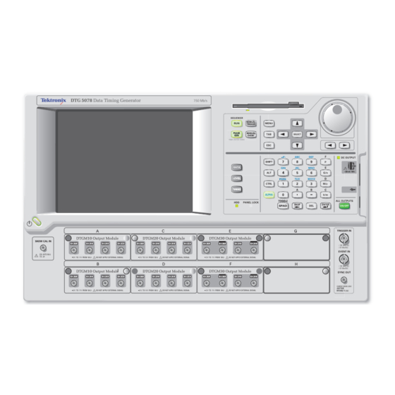
Using the Menu System on page 2-41 provides an overview of the menu and key operations of the data timing generator. Front Panel Figure 2-1: Front panel (DTG5078) DTG5078 & DTG5274 & DTG5334 Data Timing Generator User Manual 1... -
Page 44: Figure 2-2: Front Panel (Dtg5274, Dtg5334)
Operating Basics Data Timing Generator DTG 5274 2.7 Gb/s DTG 5334 Data Timing Generator 3.35 Gb/s Figure 2-2: Front panel (DTG5274, DTG5334) DTG5078 & DTG5274 & DTG5334 Data Timing Generator User Manual 1... -
Page 45: Figure 2-3: Front Panel Controls
If you press any arrow key in this state, the key operates on the menu bar area. Pressing the ESC key twice moves the focus to the lower window area. DTG5078 & DTG5274 & DTG5334 Data Timing Generator User Manual 1... - Page 46 . To actually output the signal through the output connectors, you must turn the Output on in the Level window or push the front panel ALL OUTPUTS ON/OFF button. DTG5078 & DTG5274 & DTG5334 Data Timing Generator User Manual 1...
-
Page 47: Front Panel Connectors
In the Data Generator mode, the physical channels that are not assigned to logic channel do not turn on. Front Panel Connectors Figure 2-4 shows the locations of the data timing generator front panel connectors. DTG5078 & DTG5274 & DTG5334 Data Timing Generator User Manual 1... -
Page 48: Figure 2-4: Front Panel Connectors
TRIGGER IN starting trigger of Burst mode on Pulse Generator operation. Input Voltage Range. –5 V to +5 V, 50 Ω –10 V to 10 V, 1 kΩ Connector: BNC DTG5078 & DTG5274 & DTG5334 Data Timing Generator User Manual 1... - Page 49 Connector: SMA A 50Ω SMA termination is provided with your data timing generator NOTE. mainframe. When you use the instrument with single end, attach the termination to the unused connector. DTG5078 & DTG5274 & DTG5334 Data Timing Generator User Manual 1...
- Page 50 Outputs eight channel DC voltage. This signal is independent of the output module signal. DC OUTPUT Output Voltage Range. – 3.0 V to 5.0 V +30mA MAX Connector: 2.54 mm 2 x 8 pin header (female) Connect a USB device. DTG5078 & DTG5274 & DTG5334 Data Timing Generator User Manual 1...
-
Page 51: Figure 2-5: Rear Panel (Dtg5078)
CLK OUT 1 CLK OUT 2 CLK OUT 3 -2 V TO 7 V 2.4 V pk-pk FROM 50 FROM 50 FOR MASTER/SLAVE OPERATION ONLY Figure 2-5: Rear panel (DTG5078) DTG5078 & DTG5274 & DTG5334 Data Timing Generator User Manual 1... -
Page 52: Figure 2-6: Rear Panel Connector
LAN is a port used to connect the data timing generator to a network. Connect a 10Base-T or 100BASE-T connector here. In the Master-Slave operation, the Master mainframe controls the Slave machine by way of network. 2-10 DTG5078 & DTG5274 & DTG5334 Data Timing Generator User Manual 1... -
Page 53: Figure 2-7: Rear Panel Connectors (Dtg5078) (2
A 50Ω SMA termination is provided with your data timing generator NOTE. mainframe. When you use the instrument with single end, attach the termination to the unused connector. DTG5078 & DTG5274 & DTG5334 Data Timing Generator User Manual 1 2-11... - Page 54 JUMP OUT1, JUMP OUT2, JUMP This signal is used to control sequence waveform jumps of slave-mainframe. Connect the JUMP OUT3 OUT1 to JUMP IN of master-mainframe. JUMP OUT3 is equipped only in DTG5078. CLK OUT 1 CLK OUT 2 CLK OUT 3...
- Page 55 10 MHz REF OUT into 50 Ω to GND 1.2 V 2.4 V into 1 MΩ to GND Impedance: 50 Ω , AC coupled 2.4 V pk-pk FROM 50 Connector: BNC DTG5078 & DTG5274 & DTG5334 Data Timing Generator User Manual 1 2-13...
-
Page 56: Figure 2-8: Screen Elements Just After The Power On
Pressing another pair of arrow keys enables the window corner. Press the Enter key for completion. Minimize Minimizes the window. Maximize Maximizes the window. Close (Alt + F4) Closes current window. 2-14 DTG5078 & DTG5274 & DTG5334 Data Timing Generator User Manual 1... -
Page 57: Table 2-6: File Menus
Moves current group position down one line. (Data-Waveform window) Move Left Moves current group position left by one. (Data-Listing window) Move Right Moves current group position right by one. (Data-Listing window) DTG5078 & DTG5274 & DTG5334 Data Timing Generator User Manual 1 2-15... -
Page 58: Table 2-8: Settings Menus
Displays the Subsequence window which creates subsequence. Jitter Generation Displays the Jitter Generation window which sets the jitter generation parameters. DC Output Displays the DC Output window which sets the DC Output parameter. 2-16 DTG5078 & DTG5274 & DTG5334 Data Timing Generator User Manual 1... -
Page 59: Table 2-9: System Menus
Startup: You can select a startup state for either default settings or the most recent settings you used. LCD Brightness: Adjusts the brightness of the display screen of the data timing generator. DTG5078 & DTG5274 & DTG5334 Data Timing Generator User Manual 1 2-17... -
Page 60: Table 2-11: Help Menus
Accessing the toolbar requires a mouse. Two types of toolbars are provided; the common toolbar to all windows and a specific toolbar for several windows. See Figure 2-9. 2-18 DTG5078 & DTG5274 & DTG5334 Data Timing Generator User Manual 1... -
Page 61: Figure 2-9: Toolbar
Click to zoom in the display (Data-Waveform window only) Click to display pattern data by group Click to display pattern data by channel Data-Listing or Data-Waveform window Figure 2-9: Toolbar DTG5078 & DTG5274 & DTG5334 Data Timing Generator User Manual 1 2-19... -
Page 62: Figure 2-10: Status Bar
Displays the sequencer status with animated screen. Run status Displays the sequencer status. Clock Output Displays the on/off of clock output. Online/Offline Displays the DTG5000 software execution mode. Appears only in the offline mode. 2-20 DTG5078 & DTG5274 & DTG5334 Data Timing Generator User Manual 1... -
Page 63: Figure 2-11: Channel Group Window
Deletes the group you selected. Delete All Group Deletes all the groups. Rename/ Renames the group you selected. Resize Group... Changes the number of channels included in the group. DTG5078 & DTG5274 & DTG5334 Data Timing Generator User Manual 1 2-21... -
Page 64: Figure 2-12: Blocks Window
The basic data pattern is called “block” in the Data Generator mode. In the Blocks window, you can create a new block, rename it, and resize or delete the block. Figure 2-12: Blocks window 2-22 DTG5078 & DTG5274 & DTG5334 Data Timing Generator User Manual 1... -
Page 65: Table 2-14: Setup Items For Blocks Window
View Waveform Views the content of the selected block in the Data-Waveform window, where you can edit its content. Delete Deletes the block on the selected line. DTG5078 & DTG5274 & DTG5334 Data Timing Generator User Manual 1 2-23... -
Page 66: Figure 2-13: Data-Listing Window
Sometimes the editing requires specifying the edit range. You can specify all of the current channels and groups, the channels and groups between markers, or the area you specified with cursor. 2-24 DTG5078 & DTG5274 & DTG5334 Data Timing Generator User Manual 1... -
Page 67: Table 2-16: Edit Menus For Data-Listing Window
Paste from Clipboard... Pastes the data copied in the Windows clipboard as characters to the location starting from the active cursor cell. Also available for importing data from other applications. DTG5078 & DTG5274 & DTG5334 Data Timing Generator User Manual 1 2-25... -
Page 68: Figure 2-14: Data-Waveform Window
Moves the data in the specified range in the vector or bitwise direction. Shift fills the empty cells with 0s. Rotate fills them with the off-screen data. Fill with One/Zero... Fills the specified range with 0s or 1s. 2-26 DTG5078 & DTG5274 & DTG5334 Data Timing Generator User Manual 1... - Page 69 Paste from Clipboard... Pastes the data copied in the Windows clipboard as text to the location starting from the active cursor cell. Also available for importing data from another application. DTG5078 & DTG5274 & DTG5334 Data Timing Generator User Manual 1 2-27...
-
Page 70: Figure 2-15: Level Window
Sets the termination impedance of the destination of the output signal. Term. V Sets the termination voltage of the destination of the output signal. Output Turns the output to on or off. 2-28 DTG5078 & DTG5274 & DTG5334 Data Timing Generator User Manual 1... -
Page 71: Table 2-19: Edit Menus For Level Window
Apply to Channels in Applies the currently selected settings to all channels within the group. the Same group Apply to All Channels Applies the currently selected settings to all channels. DTG5078 & DTG5274 & DTG5334 Data Timing Generator User Manual 1 2-29... -
Page 72: Figure 2-16: Timing Window (Data Generator Mode)
Shows the physical channel assigned in the Channel Group window. Format Selects NRZ, RZ or R1 for the pattern format. Delay Sets the lead delay (time or percentage). 2-30 DTG5078 & DTG5274 & DTG5334 Data Timing Generator User Manual 1... -
Page 73: Table 2-21: Edit Menus For Timing Window
Normal | AND | XOR Sets the channel addition mode (when Channel Addition is selected). 1ns | 2ns Sets the jitter range of the DTGM32 output module (when Jitter Range is selected). DTG5078 & DTG5274 & DTG5334 Data Timing Generator User Manual 1 2-31... -
Page 74: Figure 2-17: Time Base Window
Specifies the trigger point (rising edge or falling edge of external trigger signal). Selects either Positive or Negative. Ω Ω) Impedance Specifies external trigger impedance. (50 or 1 k 2-32 DTG5078 & DTG5274 & DTG5334 Data Timing Generator User Manual 1... - Page 75 Specifies rising or falling edge. (Normal or Invert) Ω Ω) Impedance Specifies event signal input impedance. (50 or 1 k Threshold Specifies event signal input threshold level. There is no Edit menu on this window. DTG5078 & DTG5274 & DTG5334 Data Timing Generator User Manual 1 2-33...
-
Page 76: Figure 2-18: Sequence Window
If the cell is left blank, control goes to the next line. Sequencer Mode Selects hardware sequence or software sequence. 2-34 DTG5078 & DTG5274 & DTG5334 Data Timing Generator User Manual 1... -
Page 77: Table 2-24: Edit Menus For Sequence Window
View Subsequence Changes the current window display to Subsequence window, where Definition shows selected subsequences. This menu selection is available when the subsequence is selected. DTG5078 & DTG5274 & DTG5334 Data Timing Generator User Manual 1 2-35... -
Page 78: Figure 2-19: Subsequence Window
Specifies the name of the block to be output on the line. Accepts up to 32 characters for each block name. Repeat Specifies the number of repetitions of the block. Accepts an integer from 1 to 65,536, but does not accept Infinite. 2-36 DTG5078 & DTG5274 & DTG5334 Data Timing Generator User Manual 1... -
Page 79: Table 2-26: Edit Menus For Subsequence Window
This menu selection is available when the block name is selected. View Waveform Switches the window display to the Data-Waveform window, where shows selected blocks. This menu selection is available when the block name is selected. DTG5078 & DTG5274 & DTG5334 Data Timing Generator User Manual 1 2-37... -
Page 80: Figure 2-20: Jitter Generation Window
Set the profile amplitude and jitter width. For the unit, you may select either s (seconds) or UI (Unit Interval, 1 clock period of data timing generator). Specifies peak-to-peak or RMS values. There is no Edit menu on this window. 2-38 DTG5078 & DTG5274 & DTG5334 Data Timing Generator User Manual 1... -
Page 81: Figure 2-21: Dc Output Window
L Limit Sets the minimum value of DC level setting range. Limit Turns on or off the High/Low limit function. Output On Powers the output on or off. DTG5078 & DTG5274 & DTG5334 Data Timing Generator User Manual 1 2-39... -
Page 82: Table 2-29: Edit Menus For Dc Output Window
Sets 1.40 V. Sets 1.00 V. TMDS High Sets 3.30 V. Sets 2.80 V. High Sets 1.80 V. Sets 1.00 V. High Sets 0.00 V. Sets – 0.41 V. 2-40 DTG5078 & DTG5274 & DTG5334 Data Timing Generator User Manual 1... -
Page 83: Figure 2-22: Menu Selection
When you press it only once, the menu bar is still active although the display disappears. In this state, you can navigate through the menu bar by pressing the 、 keys. DTG5078 & DTG5274 & DTG5334 Data Timing Generator User Manual 1 2-41... -
Page 84: Figure 2-23: Window Operation 1: Time Base Window
Figure 2-23: Window operation 1: Time Base window 2-42 DTG5078 & DTG5274 & DTG5334 Data Timing Generator User Manual 1... -
Page 85: Table 2-31: Time Base Window Operation
For details, see Numeric Input on page 2-50. To place the check sign into a check box such as Output On, use the SPACE key. SPACE DTG5078 & DTG5274 & DTG5334 Data Timing Generator User Manual 1 2-43... -
Page 86: Figure 2-24: Window Operation 2: Timing Window
For Format, Polarity, or Mode selections, first display the pop-up menu, then select the parameter. 6. The scroll bar is activated when the mouse is attached. Scroll the cursor to display the hidden tables outside the display area. 2-44 DTG5078 & DTG5274 & DTG5334 Data Timing Generator User Manual 1... -
Page 87: Table 2-32: Timing, Level, Data-Listing Window Operation
You can select either View By Channel or View By Group window display. You can toggle between the two by using View menu in the Data-Listing or Data-Waveform windows. DTG5078 & DTG5274 & DTG5334 Data Timing Generator User Manual 1 2-45... -
Page 88: Figure 2-25: Window Operation 3: Data-Listing Window
To... from the Edit menu to display the Move Marker To dialog. Then, enter the value to each field. You cannot move the markers with front panel keys or knob. You can move the markers by dragging a mouse in the Data-Waveform window. 2-46 DTG5078 & DTG5274 & DTG5334 Data Timing Generator User Manual 1... - Page 89 You can select either View By Channel or View By Group window display. You can toggle between the two by using View menu in the Data-Listing or Data-Waveform windows. DTG5078 & DTG5274 & DTG5334 Data Timing Generator User Manual 1 2-47...
-
Page 90: Figure 2-26: Window Operation 4: Channel Group Window
To create, resize or deassign a group, or create a predefined group, use the Edit menu or the pop-up menu displayed by pushing the SELECT button. 2-48 DTG5078 & DTG5274 & DTG5334 Data Timing Generator User Manual 1... -
Page 91: Figure 2-27: Window Operation 5: Sequence Window
Edit menu, which allows you to specify the block or subsequence in the Block/Subsequence column. You can also specify the block or subsequence by using the SELECT button and pop-up menu. DTG5078 & DTG5274 & DTG5334 Data Timing Generator User Manual 1 2-49... -
Page 92: Table 2-36: Example Of Numeric Keys Input
To move the underbar to the target digit to be edited, use the Left and/or Right arrow key under the knob. See Figure 2-3 for the location of the key. A numeric value accompanied with underbar 2-50 DTG5078 & DTG5274 & DTG5334 Data Timing Generator User Manual 1... -
Page 93: Table 2-37: Example Of Numeric Keys Input
Any key unrelated to text input or ESC key, or use the ENTER key to determine the character, the mode automatically changes from text input to numeric input. DTG5078 & DTG5274 & DTG5334 Data Timing Generator User Manual 1 2-51... -
Page 94: Table 2-38: Selecting A File
Press the repeatedly to activate the file view. Activates the file view Browsing a folder: :select the folder. : open the folder : move the folder hierarchy up 2-52 DTG5078 & DTG5274 & DTG5334 Data Timing Generator User Manual 1... -
Page 95: Table 2-39: Key Operations
Moves the cursor through items on the menu, moves the caret during text input, or selects a radio button. Selects multiple items (Data-Listing/Data-Waveform window), or shifts the current line (SHIFT + Up/Down arrow key only; Timing/Level window). DTG5078 & DTG5274 & DTG5334 Data Timing Generator User Manual 1 2-53... - Page 96 Moves the cursor between digits during numeric input. Increments or decrements the value during numeric input. Displays the Windows Start menu. Forcibly exits the application. (Available only from the external key board) 2-54 DTG5078 & DTG5274 & DTG5334 Data Timing Generator User Manual 1...
- Page 97 Windows. Connect the keyboard supplied with the instrument before turning on the power. If you need to perform the system recovery, you must use a PS/2 keyboard NOTE. and PS/2 mouse. DTG5078 & DTG5274 & DTG5334 Data Timing Generator User Manual 1 2-55...
- Page 98 Operating Basics 2-56 DTG5078 & DTG5274 & DTG5334 Data Timing Generator User Manual 1...
- Page 99 Data Structure...
-
Page 101: Figure 3-1: Channels, Groups, Blocks And Channel Assignment
DTG software consists of the channel, group, block, and sequence objects. This section details them in order. Block Group 01 Group 02 Group 03 Channel Assignment Physical Channels Figure 3-1: Channels, groups, blocks and channel assignment DTG5078 & DTG5274 & DTG5334 Data Timing Generator User Manual 1... -
Page 102: Table 3-1: The Number Of Available Physical Channels
The data timing generator has two types of channels: logical and physical. Logical channels represent one-bit pattern data. The number of logical channels is 32 (4 channels x 8 slots) for the DTG5078, or 8 (2 channels x 4 slots) for the DTG5274 and DTG5334. - Page 103 The number of logical channels that the system can accept is determined by the mainframe (32 for the DTG5078, 8 for the DTG5274, and DTG5334). In the Master-Slave operation mode, the number increases with the number of mainframes.
-
Page 104: Figure 3-2: Concept Of Data And Window
Block3 x 10 Timing window Block3 Freq 375 MHz Group Delay 1 ns Duty 50 % Channel Group window Grouping Channel Assignment Hardware channels Figure 3-2: Concept of data and window DTG5078 & DTG5274 & DTG5334 Data Timing Generator User Manual 1... -
Page 105: Figure 3-3: Channel Assignment
BBB:03 BBB:04 The logical channel which is not as signed to any physical channel Crossing is acceptable. can be used. Figure 3-3: Channel assignment DTG5078 & DTG5274 & DTG5334 Data Timing Generator User Manual 1... -
Page 106: Figure 3-4: Channel Group Window
Number of Channels. 1 to 96. Predefined Grouping Options. The data timing generator provides three user-selectable predefined options for grouping: 8 channels per group 1 channel per group All channels in one group DTG5078 & DTG5274 & DTG5334 Data Timing Generator User Manual 1... - Page 107 Rename/Resize Group..5. Edit the group name and the number of bits (the number of logical channels) in the Grouping dialog box. 6. Select OK to complete the change. DTG5078 & DTG5274 & DTG5334 Data Timing Generator User Manual 1...
- Page 108 The installed physical channels are displayed in the right window pane of display area. Any channel indicated by a bullet in a white rectangle has already been assigned to a logical channel. DTG5078 & DTG5274 & DTG5334 Data Timing Generator User Manual 1...
- Page 109 Alternatively, place the mouse pointer in the Group List table and right-click, then select Auto Assign. 4. A confirmation dialog box appears. 5. Select OK to perform the Auto-Assign. DTG5078 & DTG5274 & DTG5334 Data Timing Generator User Manual 1...
- Page 110 Alternatively, place the mouse pointer in the Group List table and right-click, then select the De-assign or De-assign All. 5. A dialog box appears to prompt you for confirmation. Select OK. 6. The channels you selected are de-assigned. 3-10 DTG5078 & DTG5274 & DTG5334 Data Timing Generator User Manual 1...
-
Page 111: Tutorials
Tutorials... -
Page 113: Figure 4-1: Confirming Offline Mode
Figure 4-1: Confirming Offline mode 1. Exit the DTG5000 software. a. Push the MENU button, and then select Exit from the File menu using the Up, Down, Left, and/or Right arrow key. DTG5078 & DTG5274 & DTG5334 Data Timing Generator User Manual 1... -
Page 114: Figure 4-2: Select The Online Mode
Press the ENTER key. 4. Restart the DTG5000 software. a. Press the CTRL+ESC keys to open the Start menu. b. Using the arrow key, select Programs > Tektronix > DTG5000 > DTG5000, and then press the ENTER key to restart the DTG5000 software. - Page 115 Up, Down, Left, Right Digit Select arrow keys arrow keys In the following tutorials, the Up, Down, Left, and Right arrow keys are simply called “arrow keys”. DTG5078 & DTG5274 & DTG5334 Data Timing Generator User Manual 1...
-
Page 116: Tutorial 1: Pulse Generator Mode
Run Mode. Confirm that the Pulse Gen is displayed Confirm that the Internal is displayed Confirm that the Continuous is displayed Figure 4-3: Time Base window (Pulse Generator mode) DTG5078 & DTG5274 & DTG5334 Data Timing Generator User Manual 1... -
Page 117: Figure 4-4: Level Window (Pulse Generator Mode)
2. Confirm that the View by Channel is selected in the View menu. 3. Do the following substeps to turn the Output on: a. Move the cursor to Output 1-A1 using the arrow keys. DTG5078 & DTG5274 & DTG5334 Data Timing Generator User Manual 1... - Page 118 4. Push the front panel RUN button to output the pulse signal. Level Window Operations The following steps introduce a variety of operations you can perform in the Level window. 1. Set the numeric values in the following ways. DTG5078 & DTG5274 & DTG5334 Data Timing Generator User Manual 1...
- Page 119 Using the arrow keys, move the cursor to High for the 1-A2 channel. Push the SELECT button to open the pop-up menu, select the Predefined Level... using the arrow keys, and then push the SELECT button. The Predefined Level dialog box appears. DTG5078 & DTG5274 & DTG5334 Data Timing Generator User Manual 1...
- Page 120 By pushing the ALL OUTPUTS ON/OFF button, you can toggle between On and Off for all the channels. Push the button twice to turn on all the channels. DTG5078 & DTG5274 & DTG5334 Data Timing Generator User Manual 1...
-
Page 121: Figure 4-5: Timing Window (Pulse Generator Mode)
Change the setting to 25.0 %. d. Press the Down arrow key to move the cursor to PW/Duty for the 1-A2 channel. DTG5078 & DTG5274 & DTG5334 Data Timing Generator User Manual 1... - Page 122 Steps 3.c and 3.d conclude that this parameter can be set in the 0.65 V/ns through 1.30 V/ns range. Turning the knob can also increase or decrease the value in the valid range. 4. Set the Polarity and Channel Addition parameters. 4-10 DTG5078 & DTG5274 & DTG5334 Data Timing Generator User Manual 1...
- Page 123 5. Push the RUN button to stop signal output. 6. Push the ALL OUTPUTS ON/OFF button to turn off the output switches for all the channels. DTG5078 & DTG5274 & DTG5334 Data Timing Generator User Manual 1 4-11...
- Page 124 In this tutorial, you name the file tutorial1. c. Press 2 once to select t, then press the Right arrow key to enter t. 4-12 DTG5078 & DTG5274 & DTG5334 Data Timing Generator User Manual 1...
- Page 125 Pulse Generator and/or Data Generator mode. You can restore the settings by loading the settings file using the Open Setup pull-down menu. This ends the Tutorial 1. DTG5078 & DTG5274 & DTG5334 Data Timing Generator User Manual 1 4-13...
-
Page 126: Tutorial 2: Data Generator Mode
1. Push the MENU button, select Settings using the arrow keys, select Blocks using the arrow keys, and then press the ENTER key to open the Blocks window. Figure 4-6: Blocks window 4-14 DTG5078 & DTG5274 & DTG5334 Data Timing Generator User Manual 1... -
Page 127: Figure 4-7: Channel Group Window
To define the block name, first select the character input mode by pressing the ALPHA key. You can set the block size from 1 to 8,000,000 for the DTG5078, or 1 to 32,000,000 for the DTG5274. The data timing generator is sometimes unable to output the pattern data due to the minimum block length or the block size granularity, depending on the operating condition. - Page 128 Any channel indicated by a bullet in a white rectangle has already been assigned to a logical channel. The logical channels can be created up to 32 channels for the DTG5078, and 8 channels for the DTG5274, and they are independent of the installed output modules.
- Page 129 Move the cursor to Group4 in the Group list. b. Push the SELECT button, select Delete Group using the Up and/or Down arrow key, and then push the SELECT button. DTG5078 & DTG5274 & DTG5334 Data Timing Generator User Manual 1 4-17...
- Page 130 1. Push the front panel DATA button. Alternatively, push the MENU button, and select Data-Listing from the Settings menu. The Data-Listing window appears. Pushing the DATA button repeatedly toggles between the Data-Listing and Data-Waveform windows alternately. 4-18 DTG5078 & DTG5274 & DTG5334 Data Timing Generator User Manual 1...
-
Page 131: Figure 4-8: Data-Listing Window
2. Push the MENU button, select Edit using the arrow keys. This opens the Edit menu, which contains edit commands. 3. Open the View menu using the Right arrow key. Edit menu View menu Figure 4-9: Edit menu and View menu DTG5078 & DTG5274 & DTG5334 Data Timing Generator User Manual 1 4-19... - Page 132 By setting the delta value, you can define the position of Marker2 relative to Marker1. Press the ENTER key to move the Maker to the vector position you defined. 4-20 DTG5078 & DTG5274 & DTG5334 Data Timing Generator User Manual 1...
-
Page 133: Figure 4-10: View By Channel And View By Group
1. Push the MENU button, then open the View menu using the arrow keys. 2. If you select View by Channel, the data is listed by the channel. If you select View by Group, the data is listed by the group. DTG5078 & DTG5274 & DTG5334 Data Timing Generator User Manual 1 4-21... - Page 134 To specify the area, use the radio buttons located in Range and By in the dialog box associated with the selected command. If you have specified View by Group, the bitwise direction is fixed to Group (group indicated by the cursor). 4-22 DTG5078 & DTG5274 & DTG5334 Data Timing Generator User Manual 1...
- Page 135 Move the cursor to any position in Group2. Repeat the same steps from 3-b through 3-f to clear all data in Group2 to 0 in the same way. DTG5078 & DTG5274 & DTG5334 Data Timing Generator User Manual 1 4-23...
- Page 136 11. In the same way, enter C to F in Vector 12 to Vector 15 in order using the unit keys. 12. Review the values you have just entered in the Data-Waveform window. a. Push the DATA button to open the Data-Waveform window. 4-24 DTG5078 & DTG5274 & DTG5334 Data Timing Generator User Manual 1...
- Page 137 Activate Pattern using the TAB key, then select Binary Counter. e. Activate Direction using the TAB key, then select Down. Use the TAB key to activate the OK button, then press the ENTER key. DTG5078 & DTG5274 & DTG5334 Data Timing Generator User Manual 1 4-25...
- Page 138 Move the cursor to any of the Group2 vectors. b. Push the SELECT button, select Clock Pattern..., and then push the SELECT button. The Clock Pattern dialog box appears. c. Press the ENTER key. 4-26 DTG5078 & DTG5274 & DTG5334 Data Timing Generator User Manual 1...
- Page 139 Push the ALL OUTPUTS ON/OFF button to turn on the output of all the channels. 3. Push the RUN button. The data is loaded into the pattern memory, and then the output begins. DTG5078 & DTG5274 & DTG5334 Data Timing Generator User Manual 1 4-27...
-
Page 140: Figure 4-11: Timing Window
The Cross Point Adjustment is available only in the following condition. The DTGM30, DTGM30 or DTGM32 output module is used. The output module is installed in slot A, B, C or D. The Format is set to NRZ. 4-28 DTG5078 & DTG5274 & DTG5334 Data Timing Generator User Manual 1... - Page 141 Frequency is restricted to 1.675 GHz for the DTG5334, 1.35 GHz for the DTG5274 and 375 MHz for the DTG5078. These values are half of the NRZ Format. 3. Push the SELECT button, select Apply to Channels in the Same Group, and then push the SELECT button.
- Page 142 5. Move the cursor to the cell where Channel Addition has been set to Normal, and then push the SELECT button. 6. Select Apply to All Channel, and then push the SELECT button. The settings for all the channels return to Normal. 4-30 DTG5078 & DTG5274 & DTG5334 Data Timing Generator User Manual 1...
-
Page 143: Tutorial 3: Creating A Sequence
Use the Down arrow key to move the cursor down one line. d. Press the ALPHA key to enter the character input mode, and then enter BinaryDown. DTG5078 & DTG5274 & DTG5334 Data Timing Generator User Manual 1 4-31... - Page 144 6. The Predefined Pattern dialog box appears. Use the TAB key and the arrow keys to select All for Range, Group for By, Binary Counter for Pattern, and Up for Direction. 4-32 DTG5078 & DTG5274 & DTG5334 Data Timing Generator User Manual 1...
-
Page 145: Figure 4-12: Subbinary And Subwalking Subsequences
The SubBinary operates as follows: Line 1. Outputs block BinaryUp 10 times before proceeding to the next line. Line 2. Outputs block BinaryDown 10 times before exiting this subsequence. DTG5078 & DTG5274 & DTG5334 Data Timing Generator User Manual 1 4-33... - Page 146 10. Repeat the same steps as SubBinary to set the WalkingOnes for Block name and 10 for repeat count on the first line, WalkingZeros for Block name and 10 for repeat count on the second line. 4-34 DTG5078 & DTG5274 & DTG5334 Data Timing Generator User Manual 1...
-
Page 147: Table 4-1: Main Sequence
Enter Start to the Label cell of Line1, and then press the ENTER key twice. 3. Use the Right arrow key to move the cursor to WaitTrig. Press the SPACE key to enter On. DTG5078 & DTG5274 & DTG5334 Data Timing Generator User Manual 1 4-35... -
Page 148: Figure 4-13: Main Sequence
Event, and Jump Timing is set to Async. Confirm that Confirm that Confirm that the Hardware the Event is the Async is is selected selected selected Figure 4-13: Main sequence 4-36 DTG5078 & DTG5274 & DTG5334 Data Timing Generator User Manual 1... -
Page 149: Figure 4-14: Flowchart
For grouping and channel assignment, use the default settings. For the Level window settings, also use the default settings. DTG5078 & DTG5274 & DTG5334 Data Timing Generator User Manual 1 4-37... - Page 150 RUN button. If the RUN button LED is not lit, this indicates that the output is off. 10. Once the output finishes, push the ALL OUTPUTS ON/OFF button to turn off the relay of the output connector. This completes Tutorial 3. 4-38 DTG5078 & DTG5274 & DTG5334 Data Timing Generator User Manual 1...
-
Page 151: Index
Index... - Page 153 2-46 Timing window, 4-29 Data-Waveform window, 2-26 Channel Addition, 4-30 Edit Menu, 2-26 Timing window, 2-31 DC OUTPUT channel assignment, 3-5, 3-9 front panel connector, 2-8 DTG5078 & DTG5274 & DTG5334 Data Timing Generator User Manual 1 Index-1...
- Page 154 2-12 TRIGGER IN, 2-6 JUMP OUT front panel connectors, 2-5 Master-Slave Connection, 2-12 Front panel control rear panel connector, 2-12 ALL OUTPUTS ON/OFF button, 2-5 Index-2 DTG5078 & DTG5274 & DTG5334 Data Timing Generator User Manual 1...
- Page 155 Network COM, 2-10 connecting, 1-10 EXTERNAL 10 MHz REF IN, 2-13 numeric input, 2-50 GPIB, 2-10 using the knob, 2-51 JUMP IN, 2-12 JUMP OU, 2-12 Keyboard, 2-10 DTG5078 & DTG5274 & DTG5334 Data Timing Generator User Manual 1 Index-3...
- Page 156 Windows operation System Menu, 2-17 Channel Group, 2-48 system software, 1-5 Data-Listing, Data-Waveform, 2-46 Sequence, 2-49 Time Base Window operation, 2-43 Timing window, 2-44 TAB key, 2-4 Technical support Index-4 DTG5078 & DTG5274 & DTG5334 Data Timing Generator User Manual 1...
- Page 157 Index XTERNAL 10 MHz REF IN rear panel connector, 2-13 DTG5078 & DTG5274 & DTG5334 Data Timing Generator User Manual 1 Index-5...
- Page 158 Index Index-6 DTG5078 & DTG5274 & DTG5334 Data Timing Generator User Manual 1...
Need help?
Do you have a question about the DTG5078 and is the answer not in the manual?
Questions and answers