Sign In
Upload
Manuals
Brands
Tektronix Manuals
Inverter
DTG5334
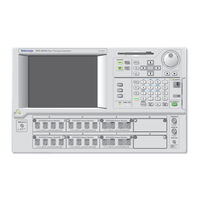
Tektronix DTG5334 Manuals
Manuals and User Guides for Tektronix DTG5334. We have
2
Tektronix DTG5334 manuals available for free PDF download: User Manual
Tektronix DTG5334 User Manual (158 pages)
Data Timing Generators
Brand:
Tektronix
| Category:
Inverter
| Size: 4 MB
Table of Contents
Table of Contents
5
Preface
13
General Safety Summary
13
About this Manual
13
Product Description
17
Table 1-1: DTG5000 Series Key Features
18
Table 1-2: DTG5000 Series Output Module Key Features
19
Table 1-3: Current Consumption Coefficient
20
Mainframe and Output Module Configuration
20
Product Software
21
Software Upgrade
22
Installation
23
Checking the Environmental Requirements
24
Table 1-4: Operating Requirements
25
Output Module
25
Connecting to a Network
26
Figure 1-1: Locations of Peripheral Connectors on Rear Panel
27
Table 1-5: Additional Connection Information
27
Connecting Peripherals
27
Figure 1-2: Principal Power Switch and AC Power Connector
28
Figure 1-3: On/Standby Switch Location
28
Powering on the Data Timing Generator
28
Setting up Windows 2000
29
Powering off the Data Timing Generator
30
Creating an Emergency Rescue Disk
32
Backing up User Files
34
Table 1-6: Instrument Options
35
Table 1-7: Power Cord Options
35
Accessories & Options
35
Table 1-8: Language Options
36
Table 1-9: Standard Accessories
37
Table 1-10: Optional Accessories
38
Operating Basics
43
Figure 2-2: Front Panel (DTG5274, DTG5334)
44
Figure 2-3: Front Panel Controls
45
Table 2-1: Front Panel Controls
45
Operating Basics
47
Front Panel Connectors
47
Figure 2-4: Front Panel Connectors
48
Table 2-2: Front Panel Connectors
48
Figure 2-5: Rear Panel (DTG5078)
51
Table 2-3: Rear Panel Connectors
51
Figure 2-6: Rear Panel Connector
52
Figure 2-7: Rear Panel Connectors (DTG5078) (2
53
Table 2-4: Rear Panel Connectors
53
Figure 2-8: Screen Elements Just after the Power on
56
Table 2-5: Control Box Menus
56
Display Area and Application Windows
56
Table 2-6: File Menus
57
Table 2-7: View Menus
57
Table 2-8: Settings Menus
58
Table 2-9: System Menus
59
Table 2-10: Options Menu
59
Table 2-11: Help Menus
60
Figure 2-9: Toolbar
61
Figure 2-10: Status Bar
62
Table 2-12: Status Bar
62
Figure 2-11: Channel Group Window
63
Table 2-13: Edit Menus for Channel Group Window
63
Figure 2-12: Blocks Window
64
Table 2-14: Setup Items for Blocks Window
65
Table 2-15: Edit Menus for Blocks Window
65
Figure 2-13: Data-Listing Window
66
Table 2-16: Edit Menus for Data-Listing Window
67
Figure 2-14: Data-Waveform Window
68
Table 2-17: Edit Menus for Data-Waveform Window
68
Figure 2-15: Level Window
70
Table 2-18: Setup Items for Level Window
70
Table 2-19: Edit Menus for Level Window
71
Figure 2-16: Timing Window (Data Generator Mode)
72
Table 2-20: Setup Items for Timing Window
72
Table 2-21: Edit Menus for Timing Window
73
Figure 2-17: Time Base Window
74
Table 2-22: Setup Items for Time Base Window
74
Figure 2-18: Sequence Window
76
Table 2-23: Setup Items for Sequence Window
76
Table 2-24: Edit Menus for Sequence Window
77
Figure 2-19: Subsequence Window
78
Table 2-25: Setup Items for Subsequence Window
78
Table 2-26: Edit Menus for Subsequence Window
79
Figure 2-20: Jitter Generation Window
80
Table 2-27: Setup Items for Jitter Generation Window
80
Figure 2-21: DC Output Window
81
Table 2-28: Setup Items for DC Output Window
81
Table 2-29: Edit Menus for DC Output Window
82
Figure 2-22: Menu Selection
83
Table 2-30: Menu Selection
83
Using the Menu System
83
Figure 2-23: Window Operation 1: Time Base Window
84
Table 2-31: Time Base Window Operation
85
Figure 2-24: Window Operation 2: Timing Window
86
Table 2-32: Timing, Level, Data-Listing Window Operation
87
Figure 2-25: Window Operation 3: Data-Listing Window
88
Table 2-33: Data-Listing, Data-Waveform Window Operation
88
Figure 2-26: Window Operation 4: Channel Group Window
90
Table 2-34: Channel Group Window Operation
90
Figure 2-27: Window Operation 5: Sequence Window
91
Table 2-35: Sequence Window Operation
91
Table 2-36: Example of Numeric Keys Input
92
Table 2-37: Example of Numeric Keys Input
93
Table 2-38: Selecting a File
94
Table 2-39: Key Operations
95
Figure 3-1: Channels, Groups, Blocks and Channel Assignment
101
Data Structure
101
Table 3-1: the Number of Available Physical Channels
102
Figure 3-2: Concept of Data and Window
104
Data Structure
105
Figure 3-3: Channel Assignment
105
Grouping and Channel Assignment
105
Figure 3-4: Channel Group Window
106
Tutorials
111
Figure 4-1: Confirming Offline Mode
113
Figure 4-2: Select the Online Mode
114
Tutorial 1: Pulse Generator Mode
116
Figure 4-3: Time Base Window (Pulse Generator Mode)
116
Tutorials
116
Figure 4-4: Level Window (Pulse Generator Mode)
117
Figure 4-5: Timing Window (Pulse Generator Mode)
121
Tutorial 2: Data Generator Mode
126
Figure 4-6: Blocks Window
126
Figure 4-7: Channel Group Window
127
Figure 4-8: Data-Listing Window
131
Figure 4-9: Edit Menu and View Menu
131
Figure 4-10: View by Channel and View by Group
133
Figure 4-11: Timing Window
140
Tutorial 3: Creating a Sequence
143
Figure 4-12: Subbinary and Subwalking Subsequences
145
Table 4-1: Main Sequence
147
Figure 4-13: Main Sequence
148
Figure 4-14: Flowchart
149
Index
151
Advertisement
Tektronix DTG5334 User Manual (196 pages)
Data Timing Generators
Brand:
Tektronix
| Category:
Portable Generator
| Size: 2 MB
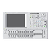
Table of Contents
Table of Contents
11
Table 1-1: Comparison between the Data Generator Mode and Pulse Generator Mode
23
Figure 1-1: Channels, Groups, Blocks and Channel Assignment
25
Table 1-2: the Number of Available Physical Channels
26
Figure 1-2: Concept of Data and Window
28
Figure 1-3: Channel Assignment
29
Figure 1-4: Channel Group Window
30
Figure 1-5: Data-Listing Window and Data-Waveform Window
35
Figure 1-6: Area
36
Table 1-3: Edited Area
36
Figure 1-7: Selection of Edited Area (View by Channel)
37
Figure 1-8: Move Cursor to Dialog Box
38
Figure 1-9: Move Marker to Dialog Box
39
Figure 1-10: View with Timing
41
Figure 1-11: Data-Listing Window Properties
42
Figure 1-12: Data-Waveform Window Properties
42
Figure 1-13: Mirror Operation
43
Figure 1-14: Predefined Pattern Dialog Box
44
Figure 1-15: Step and Skip
45
Table 1-4: Predefined Pattern Settings
45
Figure 1-16: Predefined Patterns
46
Figure 1-17: User Defined Patterns Dialog Box
47
Figure 1-18: PRBS/PRWS Dialog Box
48
Figure 1-19: Shift Register Generator Representation Example
48
Table 1-5: PRBS/PRWS Dialog Box Settings
49
Figure 1-20: Import Dialog Box
51
Figure 1-21: AWG File Import Dialog Box
52
Table 1-6: AWG File Import Dialog Box Settings
52
Figure 1-22: TLA Data Exchange Format Example
54
Figure 1-23: HFS Vector File (*.Vca) Example
56
Figure 1-24: Timing Window (Data Generator Mode)
59
Figure 1-25: Data Format
60
Figure 1-26: Clock Source in Time Base Window
61
Table 1-7: Clock Source
61
Figure 1-27: Selecting a Clock Source
62
Table 1-8: Valid Frequency Range and Step Size by Clock Source (Data Generator Mode)
63
Table 1-10: Restrictions on Using External Clock Input
66
Table 1-11: Restrictions on Using External PLL Input
67
Figure 1-28: PLL Clock Multiple Rate
69
Figure 1-29: Rates and Frequencies
69
Figure 1-30: Definition of Pulse Parameters
70
Table 1-12: Pulse Parameters
70
Table 1-13: Valid Ranges of Delay Offset
71
Figure 1-31: Definition of Pulse Parameters
72
Table 1-14: Valid Ranges of Lead Delay
73
Table 1-15: Valid Ranges of Trail Delay
74
Figure 1-32: Slew Rate
76
Table 1-16: Slew Rate Control
76
Figure 1-33: Cross Point Control
77
Table 1-17: Cross Point Control
77
Figure 1-34: Writing the Pattern into the Memory While Displacing It
78
Figure 1-35: Enlarging the Clock Pattern and Speeding up the Hardware Clock
79
Figure 1-36: Obtaining a Long Delay
79
Table 1-18: Characteristics of Long Delay
80
Table 1-19: Clock Range if the Pattern Contains Only NRZ
81
Table 1-20: Clock Range if the Pattern Includes RZ or R1
82
Table 1-21: Clock Range Used Internally in Pulse Generator Mode
83
Figure 1-38: Channel Addition
86
Figure 1-39: Jitter Range of the DTGM32
87
Figure 1-40: Level Window (Data Generator Mode)
89
Figure 1-41: Output Level, Termination Resistor, Termination Voltage
90
Table 1-22: Range of Output Level Parameters
90
Figure 1-42: Jumpers on the DTGM21
94
Table 1-23: Predefined Output Levels
96
Figure 1-43: DC Output Pin Assignments
97
Figure 1-44: DC Output Window
97
Table 1-24: Predefined DC Levels
99
Clock Source (Pulse Generator Mode)
99
Figure 1-45: Trigger Parameters
101
Figure 1-46: Time Base Window (Data Generator Mode)
102
Table 1-25: Trigger Parameters on Time Base Window
102
Figure 1-47: the Procedure of Sequence Creation
104
Table 1-26: Differences between Hardware and Software Sequencers
105
Table 1-27: Jump Modes
106
Table 1-28: Jump Timing
106
Figure 1-48: Sequence Window
107
Table 1-29: Setup Items for Sequence Window
107
Table 1-31: Jitter Generation Window Settings
116
Table 1-32: Maximum Jitter Amplitude
118
Table 1-33: External Jitter
119
Table 1-34: Setting for DTG5000 Configuration Utility in Online Mode
123
Table 1-35: Setting for DTG5000 Configuration Utility in Offline Mode
124
Table 1-36: Comparison between the Data Generator Mode and Pulse Generator Mode
138
Table 1-37: Setup Items for Time Base Window
139
Table 1-38: Setup Items for Level Window
141
Table 1-39: Setup Items for Timing Window
142
Table 1-40: Valid Frequency Range and Step Size by
144
Table 1-41: Setup Items for DC Output Window
145
Advertisement
Related Products
Tektronix DTG5078
Tektronix DTG5274
Tektronix DG2020A
Tektronix DTG5000 Series
Tektronix DTM500 Series
Tektronix DTM510
Tektronix DTM520
Tektronix DTM900
Tektronix DTM920
Tektronix DPO5204B
Tektronix Categories
Test Equipment
Measuring Instruments
Amplifier
Portable Generator
Printer
More Tektronix Manuals
Login
Sign In
OR
Sign in with Facebook
Sign in with Google
Upload manual
Upload from disk
Upload from URL