
Related Manuals for Taylor CD-i


Summary of Contents for Taylor CD-i
- Page 1 TAYLOR STUDWELDING SYSTEMS LIMITED OPERATING GUIDE TYPE CD-i CAPACITOR DISCHARGE STUDWELDING EQUIPMENT V-21A A TAYLORMADE CAPACITOR DISCHARGE STUDWELDING SYSTEM...
- Page 2 INDEX PAGE No. CONTENT USEFUL INFORMATION. IMPORTANT SAFETY INFORMATION. INTRODUCTION TO STUDWELDING. GUIDE TO EXTERNAL FEATURES. SETTING UP AND WELDING. WELD SETTINGS. WELD TESTING. PARTS LIST & EXPLODED DIAGRAMS. CIRCUIT SCHEMATIC - WIRING. DECLARATION OF CONFORMITY. V-21A...
-
Page 3: Useful Information
USEFUL INFORMATION MANUFACTURERS DETAILS TAYLOR STUDWELDING SYSTEMS LIMITED COMMERCIAL ROAD DEWSBURY WEST YORKSHIRE WF13 2BD ENGLAND TELEPHONE +44 (0)1924 452123 FACSIMILE +44 (0)1924 430059 email sales@taylor-studwelding.com www.taylor-studwelding.com SALES DIRECT TEL +44 (0)1924 487703 TECHNICAL HELPLINE : +44 (0)1924 487701 You may wish to record the details of your controller below as this information will help with any technical assistance you may require: CONTROLLER SERIAL No. -
Page 4: Further Information
NEVER OBSTRUCT THE UNDERSIDE, FRONT OR REAR PANELS AS THIS MAY CAUSE THE UNIT TO OVERHEAT DURING OPERATION. DO NOT USE THIS WELDING POWER SOURCE FOR PIPE THAWING. Taylor Studwelding Systems Limited reserves the right to amend the contents of this guide without notification. V-21A... -
Page 5: Important Safety Information
IMPORTANT SAFETY INFORMATION ! PROTECT YOURSELF AND OTHERS ! Read and understand these safety notes. 1. ELECTRICAL No portion of the outer cover of the welding controller should be removed by anyone other than suitably qualified personnel and never whilst mains power is connected. ALWAYS disconnect the mains plug from the socket. -
Page 6: Maintenance
During welding operations, intense magnetic and electrical fields are unavoidably produced and these may interfere with other sensitive Electronic equipment. All Taylor Studwelding equipment is designed, manufactured and tested to conform the current appropriate European standards and directives regarding electromagnetic emissions and immunity and as such is safe to use in any normal environment. - Page 7 INTRODUCTION TO STUDWELDING INTRODUCTION The complete range of Taylor Studwelding Systems Capacitor Discharge units are compact, portable Stud Welding equipment's. The units are specifically designed to enable a small diameter range of ferrous and non-ferrous weld studs to be welded to light gauge, self-finish or pre-coated materials, in most cases with little or no reverse marking.
-
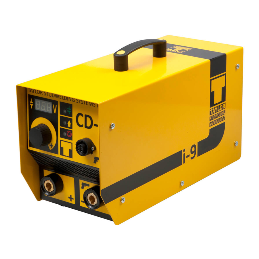
Page 8: Front Panel
GUIDE TO EXTERNAL FEATURES FRONT PANEL CARRYING HANDLE WELDING VOLTAGE DISPLAY WELDING VOLTAGE CONTROL KNOB VENTILLATION HOLES ! DO NOT OBSTRUCT ! WELDING EARTH PANEL CONNECTOR GREEN LED - INDICATES READY TO WELD AMBER LED - INDICATES UNIT IS CHARGING RED LED - INDICATES UNIT IS IN RESET MODE. -
Page 9: Options Available
GUIDE TO EXTERNAL FEATURES BACK PANEL 1. RATING/SERIAL PLATE 4. MAIN FUSE 2. ON/OFF SWITCH 5. MAINS INLET - IEC SOCKET OR 3. VENTILLATION FAN/GRILLE - ! DO NOT OBSTRUCT ! FIXED CABLE (SEE INSET) OPTIONS AVAILABLE IMPORTANT NOTES ! Due to the power requirements and Electromagnetic emissions produced during normal use, this machine must only be operated in an industrial environment. - Page 10 SETTING UP AND WELDING Set up the control unit at the place of work, ensuring that the mains switch is in the OFF position. Ensure that this is done in line with the notes and safety recommendations on pages 5 and 6 of this manual.
- Page 11 SETTING UP AND WELDING Connect the welding pistol control cable to the panel mounted socket on the controller. Note that the cable end plug and panel mounting socket are keyed to prevent incorrect fitting. Push the plug firmly home and twist the locking ring clockwise to secure the plug in position.
-
Page 12: Not Recommended
WELD SETTINGS This page and the following are intended as a guide to setting your machine. The settings outlined in the table are only intended as a starting point. It is possible that the settings will give satisfactory results without adjustment, but in reality the quality of the welding results is governed by many variable factors. - Page 13 WELD SETTINGS STUD Ø STUD M VOLTAGE SPRING VOLTAGE SPRING VOLTAGE SPRING M2.5/M3 2½ 2½ 2½ 2½ 2½ 2½ 2½ 2½ 2½ 2½ 2½ 2½ 2½ 2½ 2½ 3½ 3½ 3½ 2½ 2½ 2½ 2½ 2½ 2½ 3½ 3½ 3½ 2½...
-
Page 14: Mechanical Tests
WELD TESTING Visual examination of weld quality can, even with limited experience, provide a useful quality assessment. In such a check the presence of a small even witness of weld material around the base of the stud flange after welding should be ensured. Poor welds are indicated by excess metal on one side of the welded flange and / or the presence of an undercut or non-fused area between the stud flange and the parent sheet or plate. - Page 15 PARTS LIST & EXPLODED DIAGRAMS ITEM No. OFF PART No. DESCRIPTION Z200-05-008 SCREW 70-105-014 HANDLE Z105-08-025 SCREW MODEL 70-105-238 70-105-239 70-105-237 LOGO STICKER 70-105-240 70-105-241 70-105-230 COVER SEE INSET MODEL IDENT STICKER 70-105-242 70-105-243 V-21A...
- Page 16 PARTS LIST & EXPLODED DIAGRAMS SEE PAGES 19 TO 21 FOR A BREAKDOWN OF THE CAPACITOR BANK SEE PAGE 17 FOR A BREAKDOWN SEE PAGE 18 FOR A BREAKDOWN OF THE BASEPLATE OF THE BACK PANEL V-21A...
- Page 17 PARTS LIST & EXPLODED DIAGRAMS ITEM No. OFF PART No. DESCRIPTION 81-104-030 KNOB 81-104-032 KNOB CAP Z200-03-010 SCREW 70-102-025 PANEL CONTROL SOCKET 70-105-231 CONTROL PANEL OVERLAY 70-105-227 BASEPLATE Z200-03-006 SCREW Z610-03-000 WASHER 70-105-220 DISPLAY PCB 81-106-031 PANEL WELD SOCKET 70-105-232 SOCKET PANEL OVERLAY 70-102-002 FOOT...
- Page 18 PARTS LIST & EXPLODED DIAGRAMS NOTE : ITEM 10 OR ITEMS 11 - 13 ARE FITTED ITEM No. OFF PART No. DESCRIPTION 70-105-294 70-105-229 BACK PANEL 70-105-142 SERIAL/RATING PLATE 70-102-018 FAN GUARD 70-105-270 ON/OFF SWITCH Z650-03-000 RIVET Z200-05-012 SCREW 70-102-085 FUSEHOLDER 70-105-236 FUSE...
- Page 19 PARTS LIST & EXPLODED DIAGRAMS ITEM No. OFF PART No. DESCRIPTION 70-105-221 MAIN PCB Z600-03-000 WASHER Z200-03-006 SCREW 70-105-228 MOUNTING PILLAR 70-105-226 WARNING STICKER 70-105-219 RESISTOR 70-105-245 WIRING HARNESS (NOT SHOWN) V-21A...
- Page 20 PARTS LIST & EXPLODED DIAGRAMS ITEM No. OFF PART No. DESCRIPTION Z200-05-008 SCREW DIODE LEAD Z605-10-000 WASHER 70-105-225 SOCKET LINK BAR Z510-10-000 LOCKNUT Z105-05-045 SCREW Z615-05-000 SPRING WASHER Z600-05-000 WASHER 70-105-224 POSITIVE BUSBAR 70-105-139 CAPACITOR SCREW Z605-05-999 WASHER Z615-05-000 SPRING WASHER Z515-05-000 70-102-131 DIODE - # NOTE.
- Page 21 PARTS LIST & EXPLODED DIAGRAMS ITEM No. OFF PART No. DESCRIPTION ITEM No. OFF PART No. DESCRIPTION Z205-04-016 SCREW 70-105-234 INSULATED FIXING BLOCK Z515-05-000 70-105-235 MOUNTING PILLAR Z615-05-000 SPRING WASHER 70-105-223 NEGATIVE BUSBAR Z605-05-999 WASHER 70-105-040 CAPACITOR 70-105-139 CAPACITOR SCREW 70-105-222 MOUNTING BRACKET 70-105-258...
- Page 22 CIRCUIT SCHEMATIC - WIRING V-21A...
-
Page 23: Eu Declaration Of Conformity
EU DECLARATION OF CONFORMITY Responsible Party Name Taylor Studwelding Systems Ltd Address Commercial Road Dewsbury West Yorkshire WF13 2BD Designation of Product : Studwelding equipment CDi series types CDi8, CDi9, CDi10 Studwelding gun series C1, C2 The above mentioned equipment complies with the requirements of the following directives :...
Need help?
Do you have a question about the CD-i and is the answer not in the manual?
Questions and answers