Table of Contents
Advertisement
Quick Links
Download this manual
See also:
Operating Manual
Service
Manual
MULTI-CD/MD CONTROL HIGH POWER MD PLAYER WITH FM/AM TUNER
MEH-P5350
- This service manual should be used together with the following manual(s):
Model No.
Order No.
CX-1020
CRT2653
- US and foreign patents licensed from Dolby Laboratories Licensing Corporation.
- The screw is not stopped in this product though there is a stamp of the screw stop in two places of a
full part in the figure below.
CONTENTS
1. SAFETY INFORMATION ............................................2
2. EXPLODED VIEWS AND PARTS LIST .......................3
4. PCB CONNECTION DIAGRAM ................................28
5. ELECTRICAL PARTS LIST ........................................37
6. ADJUSTMENT..........................................................41
PIONEER CORPORATION
PIONEER ELECTRONICS SERVICE INC.
PIONEER EUROPE N.V.
Haven 1087 Keetberglaan 1, 9120 Melsele, Belgium
PIONEER ELECTRONICS ASIACENTRE PTE.LTD. 253 Alexandra Road, #04-01, Singapore 159936
C PIONEER CORPORATION 2001
Mech. Module Remarks
MD-4LP
MD Mech. Module:Circuit Description, Mech.Description, Disassembly
4-1, Meguro 1-Chome, Meguro-ku, Tokyo 153-8654, Japan
P.O.Box 1760, Long Beach, CA 90801-1760 U.S.A.
7. GENERAL INFORMATION .......................................44
7.1 DIAGNOSIS ........................................................44
7.1.1 TEST MODE ................................................44
7.1.2 DISASSEMBLY............................................48
7.2 PARTS .................................................................51
7.2.1 IC..................................................................51
7.2.2 DISPLAY ......................................................57
7.3 OPERATIONAL FLOW CHART ...........................58
8. OPERATIONS AND SPECIFICATIONS.....................59
K-ZZU. MAR. 2001 Printed in Japan
ORDER NO.
CRT2654
ES
Advertisement
Table of Contents

Related Manuals for Pioneer MEH-P5350


Summary of Contents for Pioneer MEH-P5350
-
Page 1: Table Of Contents
PIONEER ELECTRONICS SERVICE INC. P.O.Box 1760, Long Beach, CA 90801-1760 U.S.A. PIONEER EUROPE N.V. Haven 1087 Keetberglaan 1, 9120 Melsele, Belgium PIONEER ELECTRONICS ASIACENTRE PTE.LTD. 253 Alexandra Road, #04-01, Singapore 159936 C PIONEER CORPORATION 2001 K-ZZU. MAR. 2001 Printed in Japan... -
Page 2: Safety Information
MEH-P5350 1. SAFETY INFORMATION This service manual is intended for qualified service technicians; it is not meant for the casual do-it-yourselfer. Qualified technicians have the necessary test equipment and tools, and have been trained to properly and safely repair complex products such as those covered by this manual. -
Page 3: Exploded Views And Parts List
MEH-P5350 2. EXPLODED VIEWS AND PARTS LIST 2.1 PACKING NOTE: - Parts marked by “*” are generally unavailable because they are not in our Master Spare Parts List. ∇ mark on the product are used for disassembly. - Screws adjacent to - PACKING SECTION PARTS LIST Mark No. - Page 4 MEH-P5350 2.2 EXTERIOR...
- Page 5 MEH-P5350 - EXTERIOR SECTION PARTS LIST Mark No. Description Part No. Mark No. Description Part No. 1 Screw BMZ30P100FMC 46 Connector CNV6691 2 Screw BSZ26P060FMC 47 Grille Unit CXB7804 3 Screw BSZ30P060FMC 48 Holder Unit CXB7439 4 Cord Assy CDE6438...
- Page 6 MEH-P5350 2.3 MD MECHANISM MODULE...
- Page 7 MEH-P5350 - MD MECHANISM SECTION PARTS LIST Mark No. Description Part No. Mark No. Description Part No. 1 MD Unit(MD-4LP) CWX2505 46 Rack CNV5624 2 Connector(CN401) CKS4055 47 Rack CNV5625 3 Connector(CN101) CKS4056 48 Roller CNV5626 4 ••••• 49 Collar...
-
Page 8: Block Diagram And Schematic Diagram
MEH-P5350 3. BLOCK DIAGRAM AND SCHEMATIC DIAGRAM 3.1 BLOCK DIAGRAM FM FRONT END FM/AM 1ST IF 10.7MHz FM MPX CN401 T51 Q51 CF51 CF52 CF53 ANTENNA DI/DO IC 2 PM4008A 34 33 41 44 11 12 13 COMP MIXER.IF AMP DET... - Page 9 MEH-P5350 SYSTEM CONTROLLER IC 601(1/2) PE5213A Q959 VDD1 Q912 DALMON CN901 BUP1 BACKUP GND1 POWER AMP RL– ELECTRICAL VOLUME/ RL– SOURCE SELECTOR IC 301 FL– PAL005A IC 151 FL– PML008A MUTE STBY B.REM B.REM B.REM Q932 ISENS Q301 MUTE Q931...
- Page 10 MEH-P5350 3.2 OVERALL CONNECTION DIAGRAM(GUIDE PAGE) Note: When ordering service parts, be sure to refer to “EXPLODED VIEWS AND PARTS LIST” or “ELECTRICAL PARTS LIST”. Large size SCH diagram MD UNIT MD:+1dBs CN301 IP-BUS Guide page Detailed page NOTE : The >...
-
Page 11: Tuner Amp Unit
MEH-P5350 TUNER AMP UNIT FM:+4.75dBs AM: -5.75dBs FM:+5.6dBs MD:+19.25dBs AM: -4.9dBs IP-BUS:+9.45dBs MD:+10.1dBs IP-BUS:+10.3dBs FM:+5.6dBs AM: -4.9dBs MD:+10.1dBs IP-BUS:+10.3dBs FM:+0.6dBs AM: -9.9dBs MD:+5.1dBs IP-BUS:+5.3dBs CEK1136 FUSE > 600µH FM:+31.6dBs AM: -21.1dBs MD:+36.1dBs IP-BUS:+36.3dBs Symbol indicates a resistor. Decimal points for resistor... - Page 12 MEH-P5350...
- Page 13 MEH-P5350...
- Page 14 MEH-P5350...
- Page 15 MEH-P5350...
- Page 16 MEH-P5350 3.3 KEYBOARD UNIT RESET KEY MICROCOMPUTER...
- Page 17 MEH-P5350 KEYBOARD UNIT CN831 LCD BACK LIGTH...
- Page 18 MEH-P5350 3.4 MD MECHANISM MODULE(GUIDE PAGE) · FOCUS SERVO LINE TRACKING SERVO LINE CARRIAGE SERVO LINE SPINDLE SERVO LINE RF AMP & 5ch Pow-Driver ⁄ ‹ fl ¤ fi ›...
- Page 19 MEH-P5350 MD UNIT ° 3V Reg DIGITAL SERVO ATRAC,ATRAC3 DECODER ‡ 3-5V LEVEL SHIFT CK SELECT MD SYSTEM CONTROLLER...
- Page 20 MEH-P5350...
- Page 21 MEH-P5350...
- Page 22 MEH-P5350...
- Page 23 MEH-P5350...
- Page 24 MEH-P5350 Notes: 1. Circled figures represent the measuring points in the circuit diagram. Waveforms 2. Reference voltage VC: 1.65V < · VC > 3. Premastered MD, Make measurements using the MMD110. Nonetheless, waveforms indicated as “Recordable MD” should be measured using the MMD212.
- Page 25 MEH-P5350 *1 Use the AGND pin for grounding. < ‡ GND > *2 Use the GND pin for grounding. < ° GND > Due to dispersion in electrical and mechanical characteristics of the MD MECH module, observed waveforms for TEY, TIN, FEY and FIN signals might be a little different from those shown below.
- Page 26 MEH-P5350 *1 Cautions on measuring While measuring, keep the leads from the measuring terminals (ADFM, ADFG and GND on the MD CORE unit) , which is connected to the probe of an oscilloscope, apart from each other. *2 Use the GND pin for grounding. < ° GND >...
- Page 27 MEH-P5350 CN401 SW1 PCB 1 2 3 4 5 6 7 8 9 10 11 12 13 S404 CSN1042 DISC SW S401 CSN1055 CLMP SW S405 CSN1052 LOAD SW S402 CSN1052 HOME SW SW2 PCB S403 CSN1053 EJCT SW LOADING...
-
Page 28: Pcb Connection Diagram
MEH-P5350 4. PCB CONNECTION DIAGRAM 4.1 TUNER AMP UNIT TUNER AMP UNIT NOTE FOR PCB DIAGRAMS 1. The parts mounted on this PCB include all necessary parts for several destination. For further information for respective destinations, be sure to check with the schematic dia- gram. - Page 29 MEH-P5350 SIDE A ANTENNA IC,Q REAR OUT IP-BUS FM/AM TUNER UNIT CN301 FRONT...
- Page 30 MEH-P5350 TUNER AMP UNIT...
- Page 31 MEH-P5350 SIDE B...
- Page 32 MEH-P5350 4.2 KEYBOARD UNIT SIDE A...
- Page 33 MEH-P5350 SIDE B...
- Page 34 MEH-P5350 4.3 MD MECHANISM MODULE SIDE A MD UNIT CN991 IC, Q PU UNIT...
- Page 35 MEH-P5350 SIDE B MD UNIT IC, Q...
- Page 36 MEH-P5350 SW1 PCB S405 LOAD SW S404 DISC SW2 PCB LOADING S403 MOTOR EJCT S402 SPINDLE HOME MOTOR S401 CLMP CN401...
-
Page 37: Electrical Parts List
MEH-P5350 5. ELECTRICAL PARTS LIST NOTES: - Parts whose parts numbers are omitted are subject to being not supplied. - The part numbers shown below indicate chip components. Chip Resistor RS1/_S___J,RS1/__S___J Chip Capacitor (except for CQS..) CKS.., CCS.., CSZS..=====Circuit Symbol and No.===Part Name Part No. - Page 38 MEH-P5350 =====Circuit Symbol and No.===Part Name Part No. =====Circuit Symbol and No.===Part Name Part No. ------ ------------------------------------------ ------------------------- ------ ------------------------------------------ ------------------------- RS1/16S222J CEJQ1R0M50 RS1/16S222J CKSRYB104K16 RS1/16S272J CEJQ470M10 RS1/16S272J CEJQNP4R7M16 RS1/16S182J CEJQNP4R7M16 RS1/16S182J CEJQNP4R7M16 RS1/16S153J CEJQNP4R7M16 RS1/16S153J CEJQNP4R7M16 RS1/16S103J CEJQNP4R7M16 RS1/16S473J...
- Page 39 MEH-P5350 =====Circuit Symbol and No.===Part Name Part No. =====Circuit Symbol and No.===Part Name Part No. ------ ------------------------------------------ ------------------------- ------ ------------------------------------------ ------------------------- TC7WT125FU RAB4C681J TC7WH34FU RAB4C104J BA5985FM RS1/16S393J BA033FP RS1/16S104J Transistor 2SB1132 RS1/16S683J Transistor UMD2N RS1/16S0R0J Transistor DTA144EU RS1/16S0R0J Transistor FMG13...
- Page 40 MEH-P5350 =====Circuit Symbol and No.===Part Name Part No. =====Circuit Symbol and No.===Part Name Part No. ------ ------------------------------------------ ------------------------- ------ ------------------------------------------ ------------------------- CKSRYB104K16 Lamp 40mA 14V CEL1687 CKSRYB471K50 Lamp 40mA 14V CEL1687 CKSRYB104K16 LCD 701 CAW1686 CKSRYB104K16 RESISTORS CKSRYB104K16 CKSRYB104K16 RS1/16S222J...
-
Page 41: Adjustment
MEH-P5350 6. ADJUSTMENT 6.1 ADJUSTING THE MD SECTION 1) Precautions Since the single voltage (3.3V) system is being employed for the regulator of this equipment, the reference potential for the servo signals becomes Vc (1.65V, approximately). In this manual, the Vc reference potential will be indicated as **Vc (e.g. 1.5Vc) and the reference GND will be indicat- ed as **V. - Page 42 MEH-P5350 - Grating adjustment 1) Regarding the TEST Disc When performing grating adjustment and grating confirmations, use the high reflection Disc (MMD-110). When confirming the operation state and automatic adjustment state, us the high reflection Disc (MMD-110) and low reflection Disc (MMD-212), respectively.
- Page 43 MEH-P5350 Ech → Xch 50mV/div, AC Grating waveform Fch → Ych 50mV/div, AC 0° 30° 45° 60° 75° 90°...
-
Page 44: General Information
MEH-P5350 7. GENERAL INFORMATION 7.1 DIAGNOSIS 7.1.1 TEST MODE (1) When entering into the TEST MODE 1 Pressing and holding the "4" key and "6" key simultaneously, turn ON the "ACC" and "B.UP" (Reset Start) at the same time. 2 Select the MD using the [SOURCE] key. - Page 45 MEH-P5350 err-n+1-xx err-n+1-xx xx:err code, NG code appear. (The NG code is of the internal mode which is not indicated under the actual product mode.) ** Once the "Test Normal" is executed, the adjusted value and the play address will be stored into the micro- computer as the LAST values.
- Page 46 MEH-P5350 - Flow Chart(Mechanism Section) ACC,Back-up ON SOURCE MD select BAND POWER ON Repetition of LOAD and EJECT, Display of number of times. The first 1bit is for load. TEST MECHA Type of EJECT, L : LOAD, E : EJECT...
- Page 47 MEH-P5350 - Flow Chart(Servo Section) Reset BAND MD select POWER ON TEST MD The displays of the the aboves two and BAND TRK + TRK – three digits are disk modes LDON OFF SET DISP1 HOME DISC identified with MODE...
-
Page 48: Disassembly
MEH-P5350 7.1.2 DISASSEMBLY Removing the Case (not shown) 1. Remove the Case. MD Mechanism Module Removing the MD Mechanism Module (Fig.1) Remove the four screws. Disconnect the connector and then remove the MD Mechanism Module. Removing the Grille Assy (Fig.1) Disconnect the three stoppers and then remove the Grille Assy. - Page 49 MEH-P5350 - Removing the PU Unit 1. Provide short solder in section A, then remove the connector 2. Remove the two screws, then erect the board in the direction indicated by the white arrow head. 3. Remove the two screws and two springs.
-
Page 50: Connector Function Description
MEH-P5350 7.1.3 CONNECTOR FUNCTION DESCRIPTION 1. BUS+ 2. GND 3. GND 4. NC 5. BUS- 6. GND 7. BUS L+ INPUT 8. ASENB 9. BUS R+ INPUT 10. BUS R- INPUT FUSE 10A 11. BUS L- INPUT 1. RR+ 2. FR+ REAR OUTPUT 3. -
Page 51: Parts
MEH-P5350 7.2 PARTS 7.2.1 IC - Pin Functions (PE5213A) Pin No. Pin Name Function and Operation swvdd Keyboard unit power supply control output Not used isens Illumination power supply sense input TESTIN Test program mode input Not used VDSEL VD select... - Page 52 MEH-P5350 Pin No. Pin Name Function and Operation RDS57K asens ACC power sense input bsens Back up power sense input TUNPDI PLL IC data input KYDT Key data input DPDT Display data output tunpck Serial clock output for PLL IC...
- Page 53 MEH-P5350 - Pin Functions (PD2068A) Pin No. Pin Name Format Function and Operation Crystal oscillator connection pin Crystal oscillator connection pin Power supply Not used Dimmer output RESET Reset 9,10 Not used Remote control reception input 12,13 Not used 14–17...
- Page 54 MEH-P5350 CXD2667R D1/GFS Generator DVSS Analog AUX2 Auto ADIP DVDD Sequencer Decoder DCHG DRAM Spindle XRAS Servo DDIN Converter DDOUT XCAS ASYO ASYI VSIO1 AVDI Shock Resistant COMP Memory Controller BIAS AVSI EFM/ACIRC Decoder FILI Subcode Processor FILO CLTV VDC3...
- Page 55 MEH-P5350 Pin Functions(PD5655A) Pin No. Pin Name Format Function and Operation Open BYTE CNVSS Open reset Resetting input XOUT Main clock oscillation pin VSS1 Main clock oscillation pin VCC1 Not used SQSY DISC sub-code Q sink/ADIP sink brst P-BUS resetting input...
- Page 56 MEH-P5350 - FM/AM Tuner Unit FM/AM TUNER UNIT FM/AM 1ST IF 10.7MHz MPXREF 41kHz AMRF T51 Q51 CF51 CF52 CF53 AMDET AMANT L ch IC 2 FM MPX R ch ANT ADJ COMP MIXER, IF AMP, DET. LDET FMANT RFGND...
-
Page 57: Display
MEH-P5350 7.2.2 DISPLAY - CAW1686... -
Page 58: Operational Flow Chart
MEH-P5350 7.3 OPERATIONAL FLOW CHART Power ON VDD=5V 41pin bsens 93pin dsens 2pin adpw←H 22pin 300ms IPPW←H 24pin ASNBO←H 25pin 300ms In case of the above signal, the communication BRST←H with Grille microcomputer may fail. 68pin If the time interval is not 300msec, the oscillator may be defective. -
Page 59: Operations And Specifications
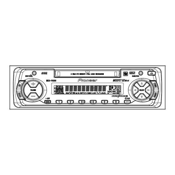
MEH-P5350 8. OPERATIONS AND SPECIFICATIONS 8.1 OPERATIONS Key Finder Head Unit EJECT button MD Loading Slot DISPLAY button EQ button BAND button FUNCTION button AUDIO button Buttons 1–6 +/– buttons 5/∞/2/3 buttons SOURCE button CLOCK button SFEQ button Remote Controller (CD-R600) The remote controller (CD-R600) enabling remote control of the head unit is sold separately. - Page 60 MEH-P5350...
- Page 61 MEH-P5350...
- Page 62 MEH-P5350...
- Page 63 MEH-P5350 - CONNECTION DIAGRAM...
-
Page 64: Specifications
MEH-P5350 8.2 SPECIFICATIONS General MD player Power source ..14.4 V DC (10.8 – 15.1 V allowable) System ........ Mini disc digital audio system Grounding system ........Negative type Usable discs ............Mini disc Max. current consumption ........10.0 A Signal format ....
Need help?
Do you have a question about the MEH-P5350 and is the answer not in the manual?
Questions and answers