
Related Manuals for Electro-Voice EVID-S10.1DW


Summary of Contents for Electro-Voice EVID-S10.1DW
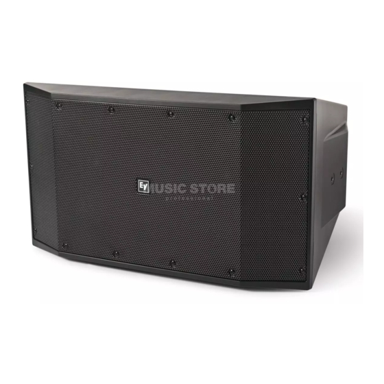
- Page 1 EVID-S Surface Mount Dual 10” Subwoofers EVID-S10.1DB | EVID-S10.1DW en | Installation manual...
-
Page 3: Table Of Contents
Transformer input panel - optional accessory 5.2.1 Mono operation 5.2.2 Stereo operation Crossover input panel - optional accessory 5.3.1 Mono operation 5.3.2 Stereo operation Troubleshooting Technical data Dimensions Frequency response and impedance U-bracket dimensions - optional accessory Electro-Voice Installation manual 2017.08 | 01 | F.01U.345.359... -
Page 4: Safety
Suspending any object is potentially dangerous and should only be attempted by individuals who have a thorough knowledge of the techniques and regulations of suspending objects overhead. Electro-Voice strongly recommends all loudspeakers be suspended taking into account all current national, federal, state, and local laws and regulations. It is the responsibility of the installer to ensure all loudspeakers are safely installed in accordance with all such requirements. -
Page 5: Short Information
The following table lists products in a family, with CTN (Commercial Type Number) and identifying product name DESCRIPTION. Description EVID-S10.1DB Cabinet subwoofer 2x10" black EVID-S10.1DW Cabinet subwoofer 2x10" white UB-10DB U-bracket for 10" subwoofer black UB-10DW U-bracket for 10" subwoofer white IP-10D-TB Transformer input 10"... -
Page 6: Introduction
EVID-S Surface Mount Dual 10” Subwoofers Introduction The EVID-S10.1D subwoofer, from Electro-Voice, is a compact, high-performance, dual woofer loudspeaker with outstanding performance for the most demanding professional and commercial sound applications. Designed and engineered for use in background and foreground music, and sound reinforcement applications, the EVID-S10.1D subwoofer is the ideal solution for indoor and outdoor applications, such as restaurants, bars, patios, retail, fitness clubs, hospitality, theme parks, leisure venues, and others. -
Page 7: Packing List
Screws for weather input cover IP65 port covers IP65 port cover screws Installation manual Table 3.1: Components list A (x 1) B (x 5) G (x 2) H (x 12) F (x 8) Figure 3.1: Components Electro-Voice Installation manual 2017.08 | 01 | F.01U.345.359... -
Page 8: Product Information
Figure 3.2: Product information (subwoofer on the right is shown upside down) Item Description Grille U-bracket mounting points M8 flying points M8 safety point Input panel Subwoofer feet Weather input cover Table 3.2: Product information 2017.08 | 01 | F.01U.345.359 Installation manual Electro-Voice... -
Page 9: Installation
Remove the two subwoofer feet with the supplied Allen wrench. Attach the mounting point covers on the U-bracket mounting points. Rotate the logo by replacing it, as shown in the Replacing the logo section. Electro-Voice Installation manual 2017.08 | 01 | F.01U.345.359... -
Page 10: Replacing The Logo
Replacing the logo An additional logo is included, vertical installation is shown. To replace the logo, do the following: Remove the existing logo. Clean the surface with alcohol. Remove the paper backing. 2017.08 | 01 | F.01U.345.359 Installation manual Electro-Voice... -
Page 11: Installing The Ip65 Port Covers
If the IP65 port cover is not properly installed, you may cause damage to the subwoofer. Remove the grille. Install the IP65 port cover. Repeat step this step to install the second IP65 port cover. Reinstall the grille. Electro-Voice Installation manual 2017.08 | 01 | F.01U.345.359... -
Page 12: Installing The U-Bracket - Optional Accessory
Suspend the subwoofer from the eyebolts using rated fittings and steel cable. Secure the subwoofer from the safety eyebolt using a rated fittings and steel cable. Installing the transformer input panel - optional accessory To install the transformer input panel, do the following: 2017.08 | 01 | F.01U.345.359 Installation manual Electro-Voice... - Page 13 Remove the standard input panel. Disconnect the standard input panel. Connect the transformer input panel. Install the transformer input panel. Install the weather cover, if applicable. Electro-Voice Installation manual 2017.08 | 01 | F.01U.345.359...
-
Page 14: Installing The Crossover Input Panel - Optional Accessory
To install the crossover input panel, do the following: Remove the standard input panel. Disconnect the standard input panel. Connect the crossover input panel. Install the crossover input panel. Install the weather cover, if applicable. 2017.08 | 01 | F.01U.345.359 Installation manual Electro-Voice... -
Page 15: Wiring
After all connections are made test the complete system operation. A: Full-range parallel out B: STEREO/MONO switch set to mono. Electro-Voice Installation manual 2017.08 | 01 | F.01U.345.359... -
Page 16: Stereo Operation
After all connections are made test the complete system operation. A: Full-range parallel out B: STEREO/MONO switch set to stereo. 2017.08 | 01 | F.01U.345.359 Installation manual Electro-Voice... -
Page 17: Transformer Input Panel - Optional Accessory
After all connections are made test the complete system operation. The speakers must be set to 70V/100V mode. A: STEREO/MONO switch set to mono. Figure 5.1: Mono configuration 1 Electro-Voice Installation manual 2017.08 | 01 | F.01U.345.359... - Page 18 EVID-S Surface Mount Dual 10” Subwoofers A: STEREO/MONO switch set to mono. Figure 5.2: Mono configuration 2 2017.08 | 01 | F.01U.345.359 Installation manual Electro-Voice...
-
Page 19: Stereo Operation
After all connections are made test the complete system operation. The speakers must be set to 70V/100V mode. A: STEREO/MONO switch set to stereo. Electro-Voice Installation manual 2017.08 | 01 | F.01U.345.359... -
Page 20: Crossover Input Panel - Optional Accessory
The option shown is using 8 ohm speakers. A: STEREO/MONO switch set to mono. B: HI-PASS 4 OHM/8 OHM switch set to 8 ohm. 2017.08 | 01 | F.01U.345.359 Installation manual Electro-Voice... -
Page 21: Stereo Operation
Both options shown are using 8 ohm speakers. A: STEREO/MONO switch set to stereo. B: HI-PASS 4 OHM/8 OHM switch set to 8 ohm. Figure 5.3: Stereo configuration 1 Electro-Voice Installation manual 2017.08 | 01 | F.01U.345.359... - Page 22 EVID-S Surface Mount Dual 10” Subwoofers A: STEREO/MONO switch set to stereo. B: HI-PASS 4 OHM/8 OHM switch set to 4 ohm. Figure 5.4: Stereo configuration 2 2017.08 | 01 | F.01U.345.359 Installation manual Electro-Voice...
-
Page 23: Troubleshooting
Poor System Check and correct the system grounding, as required. Grounding or Ground Loop If these suggestions do not solve your problem, contact your nearest Electro-Voice dealer or Electro-Voice distributor. Electro-Voice Installation manual 2017.08 | 01 | F.01U.345.359... -
Page 24: Technical Data
(8) screws for the weather input cover, (2) IP65 port covers, (12) IP65 port cover screws Packaged quantity: 1 Half space (wall mounting). Half space (on wall) averaged 50 Hz – 150 Hz, 1 W. Without U-Bracket. 2017.08 | 01 | F.01U.345.359 Installation manual Electro-Voice... -
Page 25: Dimensions
[20.96 in] 650.7 mm [25.62 in] 490.8 mm [19.32 in] 356.0 mm 360.5 mm [14.02 in] [14.19 in] 578.8 mm [22.79 in] Frequency response and impedance Figure 7.1: Frequency response and impedance Electro-Voice Installation manual 2017.08 | 01 | F.01U.345.359... - Page 26 EVID-S Surface Mount Dual 10” Subwoofers Figure 7.2: Frequency response and impedance with cross-over 2017.08 | 01 | F.01U.345.359 Installation manual Electro-Voice...
-
Page 27: U-Bracket Dimensions - Optional Accessory
0.51 in] 632.0 mm [24.88 in] 220.0 mm [8.66 in] 2x 21.0 mm [2x 0.82 in] 316.0 mm [12.44 in] 2x 21.0 mm [2x 0.82 in] 3x 50.0 mm [3x 1.97 in] Electro-Voice Installation manual 2017.08 | 01 | F.01U.345.359... - Page 28 Bosch Sicherheitssysteme GmbH Bosch Security Systems, Inc Robert-Bosch-Ring 5 12000 Portland Avenue South 85630 Grasbrunn Burnsville MN 55337 Germany www.boschsecurity.com www.electrovoice.com © Bosch Sicherheitssysteme GmbH, 2017...
Need help?
Do you have a question about the EVID-S10.1DW and is the answer not in the manual?
Questions and answers