Table of Contents
Advertisement
Advertisement
Table of Contents

Related Manuals for BIOTRONIK ICS 3000


Summary of Contents for BIOTRONIK ICS 3000
- Page 3 It was approved by independent Notified Bodies and is therefore designated with the CE mark. The product can be used BIOTRONIK GmbH & Co. KG in all European Union countries as well Woermannkehre 1 as in countries that recognize the above- 12359 Berlin ·...
-
Page 4: Table Of Contents
Introduction ..........3 Safe Handling of the ICS 3000 ......4 Intended Use . - Page 5 Contents Care and Maintenance ........32 Cleaning and Disinfection .
-
Page 6: Introduction
Software for programmer, implant programs ICS 3000 SW Please comply with the technical manuals for the Note: software and the connected devices. Warranty Improper use of the equipment will cause the warranty for the ICS 3000 and accessories to become invalid. -
Page 7: Safe Handling Of The Ics 3000
If these values are not met, inaccurate results may be produced. Do not use the ICS 3000 on the patient in conjunction WARNING! with RF-surgical equipment. During diagnosis, therapy or implantation with the... - Page 8 Safety Instructions Device Combinations When using devices in combinations, it is absolutely Caution! essential that all the devices are connected to permanently installed outlets of the same power supply destined for medical use. Do not use any outlets that can be moved (such as extension cables, multiple outlets, etc.).
- Page 9 Accessories • Use only accessories that have been approved by BIOTRONIK. BIOTRONIK-approved device combinations can be used if the device to be connected complies with the IEC 601 / EN 60601 / VDE 0750 standards series and this conformity is substantiated by CE certification conducted by an independent, Notified Body.
- Page 10 Caution! medical purposes (in accordance with DIN VDE 0107:1994). Do NOT operate the ICS 3000 in areas where there is a risk of explosion. The ICS 3000 is designed to be operated and stored in Note: an enclosed area. •...
- Page 11 — Remove the source of the interference from the vicinity of the ICS 3000. — Move the ICS 3000 away from the vicinity of the source of interference. — Switch the ICS 3000 off and then on again. — If the interference persists, contact BIOTRONIK or...
-
Page 12: Instructions For Use
System error messages are generated optically and/ Note: or acoustically. The ICS 3000 may NOT be used as a life support Note: system. The ICS 3000 is portable. The Docking Station and... - Page 13 Never sterilize the ICS 3000. Caution! Do not operate the ICS 3000 near flammable or Caution! explosive materials. The ICS 3000 may be used only in spaces suited for Caution! medical purposes and equipped with grounded alternating current. Connecting the programmer to the patient •...
- Page 14 Self-test After it has been turned on, the device carries out self- tests for approximately 1 minute. The ICS 3000 cannot be used during the self-test. To WARNING! ensure the device is always ready for operation, do not switch it off during an examination.
-
Page 15: Power Supply
Power Supply Power Supply The ICS 3000 has an internal 9.6 V NiMH rechargeable battery. Nickel metal hydride rechargeable batteries have a service life of 500 to 700 charging cycles. Under optimal conditions, the capacity of 3800 mAh suffices for an uninterrupted system operating time in modular mode of approximately 1.5 hours. - Page 16 Switching On the System Use the On/Off button on the Operation Module to On/Off button switch on both components if they are connected to each other for stationary operation and connected to the power supply. When the Docking Station is switched on, the green LED on the right side of the housing will be illuminated.
-
Page 17: Switching Off The System
Switching Off the System Switching Off the System When you press the On/Off button quickly, the Normal shut-down Operation Module switches to standby mode within a few seconds. — The data are saved. — The screen goes black. — The battery level of the rechargeable battery is checked;... - Page 18 Switching Off the System Automatic Battery Recharge Automatic battery recharging begins after a normal shut-down. The recharging status is shown graphically on the Operation Module display as a percentage. The LEDs light up in reverse sequence; see „Battery level indicator“ on page 12. Depending on the battery level, recharging may take up to 4 hours.
-
Page 19: Battery Maintenance
Battery Maintenance Battery Maintenance The rechargeable battery is automatically serviced every 4 weeks after normal shut-down, if the ICS is configured to do this (see technical manual for the software). The maintenance cycle lasts approximately 12 hours, and includes battery charging, complete discharge and recharge. -
Page 20: Docking Station
Carrying handle When you press the handle release key, the handle is Note: immediately fully extended. To lift the ICS 3000 by its handle, fold the Operation Caution! Module down completely; otherwise the programming head could fall out of its holder. - Page 21 CD Drive The CD drive is used for updating ICS software, the installation of the CD supplied by BIOTRONIK with instructions for use, and – if a CD writer is available – data back-up. •...
- Page 22 Docking Station Internal Printer The ICS 3000 includes a high-resolution, graphics- capable thermal printer. The device prints on ICS 3000 thermal folding paper (see „Scope of Delivery“ on page 39). The thermal paper printouts are moisture-sensitive Note: and fade when exposed to strong sunlight. Make copies for permanent documentation.
-
Page 23: Ports On The Docking Station
26. This port can be used, for example, to connect the Serial port BIOTRONIK CDM 3000 Cardiac Data Manager. • Connect a standard 9-pin RS-232 interface connector. All the connector pins must be fully assigned and connected 1:1. -
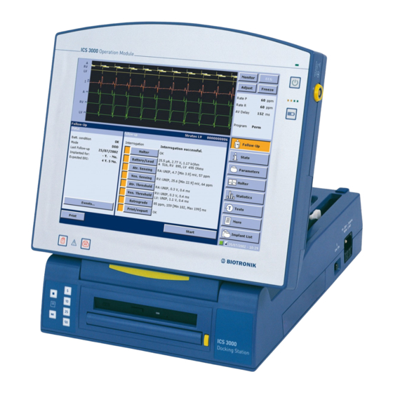
Page 24: Operation Module
Operation Module Operation Module The Operation Module is the central operating, control PC based and data storage unit for the entire system. For information on the power supply, see page 12. See also „Connecting and Disconnecting the Operation Module“ on page 18. —... -
Page 25: Ports On The Operation Module
Ports on the Operation Module Ports on the Operation Module The ECG and PGH ports are mechanically coded; it is Note: not possible to connect the cables incorrectly. The ECG module is used with extremity leads: ECG port 3-channel ECG (Einthoven) and a miniclinic to monitor the functioning of implants. -
Page 26: Pgh Programming Head
(Programming implant takes place by means of telemetry via the head) ICS 3000 PGH (programming head). The output data from the implant (digital and analog) are converted into digitally coded impulses and transmitted over an inductive coupling between the coils of the programming head and those of the implant. - Page 27 PGH Programming Head Each programming head features a diagram of the Note: implant to assist in positioning the head. Silicone nubs on the underside prevent the head from slipping. To program and interrogate the implant, the Caution! programming head is brought into physical contact with the patient.
- Page 28 PGH Programming Head Conductor to ICS: PGH with straight cable The ICS 3000 is operated with the PGH programming head, which may have a spiral cable or a straight cable as a conductor. If the Operation Module is used in portable fashion, there is a danger of tripping if there is a straight cable hanging down loose.
-
Page 29: Using Basic Functions
USB port of the ICS 3000 Docking Station. • The printer is powered via the mains supply and is connected to the USB port of the ICS 3000 via an isolating separator (EN 60601-1-1, Paragraph 17.201) with a dielectric strength of at least 1.5 kV (e.g. an isolating USB-hub model UISOHUB4 by B&B... -
Page 30: Ics 3000 Software
ICS 3000 Software ICS 3000 Software Software updates are performed by authorized persons using a CD-ROM. Technical manuals for the implant programs are Installing the CD supplied on an additional CD. The CD contains technical manuals in PDF format for printing and in HTML format for help. -
Page 31: Recording Ecgs And Iegms
Recording ECGs and IEGMs Recording ECGs and IEGMs The intracardiac electrograms received from the implant as well as the surface ECG and the esophageal lead can be simultaneously displayed and printed. The recording of the surface ECG does not depend on other functions, so that the implant can be interrogated and programmed during the ongoing ECG display. -
Page 32: Data Transfer
These parameter sets are combined and saved in the program that is currently in use. The ICS 3000 detects obvious programming errors and requires these to be corrected before the program is transferred to the implant. - Page 33 Module or the programming head (see page 23). Calling up and Triggering an Emergency Shock In the ICS 3000, the emergency shock command is issued by the hardware button; the emergency shock is always generated by the implant according to the preset implant program.
-
Page 34: Non-Invasive Programmed Stimulation
Analog Telemetry Transmitting real-time measurement data from the implant to the ICS 3000 is known as analog telemetry. This includes the battery and electrode measurement data as well as intracardiac electrograms with event markers. -
Page 35: Care And Maintenance
Perform maintenance tasks only when the device is WARNING! unplugged. Depleted rechargeable batteries can be replaced; Changing the rechargeable contact BIOTRONIK. battery After a battery change, a complete battery Caution! maintenance cycle must be carried out so that the rechargeable battery reaches its full capacity and this can be displayed. -
Page 36: Sterilization
The devices used for the electrical function test are Note: usually not readily available in hospitals. Therefore, it is recommended that the ICS 3000 be checked by BIOTRONIK or by a test center authorized by BIOTRONIK. •... -
Page 37: Changing A Fuse
Before changing the fuses, you must turn off the Caution! ICS 3000 and unplug the power supply cable. • To unlock the drawer, push the latches at the right and left of the drawer inwards together. -
Page 38: Technical Data
Technical Data Technical Data ICS 3000: General Information 322*168*332 (W*H*D) Dimensions [mm] I (DIN EN 60601-1, Section 5.1 Safety class IP 20, IEC 60529 Protection degree None; DIN EN 60601-1, Section 39 Protection degree for anesthetics Continuous operation Operating mode... - Page 39 Technical Data LCD screen TFT; color Type 12.1; active diagonal Size ["] 800*600; SVGA Resolution [dpi] 80 cd/m ; with battery operation (software- Brightness (programmable) dependent) 200 cd/m ; with battery operation (software- dependent) ECG module: General Information BF, EN 60601-1, Section 5.2 Protection degree 0.7;...
- Page 40 Technical Data Miniclinic Single- and multi-chamber Stimulation modes 30 … 180; ±2 Pacing rate [ppm] 333 … 2000; 2 ±4 Period [ms] 0,1 … 2,5; 0,05 ±0,05 Pulse width (A+V) [ms] 50 … 300; 2 ±4 AV conduction time [ms] 2 …...
- Page 41 Technical Data Power Supply Primary clocked broadband power supply Type 100 – 115 V ± 10% / 60 Hz / 1.2 A / AC Mains voltage [V], Frequency [Hz] 220 – 230 V ± 10% / 50 Hz / 0.6 A / AC I, DIN EN 60601-1, Sec.
-
Page 42: Scope Of Delivery
Scope of Delivery Scope of Delivery The software must be ordered separately. Note: Standard Order number ICS 3000 Complete Complete system with accessories 336828 Complete system with accessories, with 349528 exclusively UL-certified components ICS 3000 Pen Stylus and holder 340295 ICS 3000PGH Spiral cable, extendable to approx. -
Page 43: Optional Accessories
2.8 meters PK-222-US / 2.8 m Same as the PK-222-EU with country-specific 335281 color coding of the banana plugs Sterile cover 1 Sterile cover for ICS 3000 PGH; single-use, 340287 cannot be re-sterilized Rechargeable battery, Replaceable rechargeable battery for the 336549 NiMH 9.6 V... -
Page 44: Country-Related Information
Country-Related Information Country-Related Information UL Certification The ICS 3000 US (order number: 349 528, ICS 3000 with Implant Module: 354 877) has been certified by Underwriters Laboratories Inc. in accordance with UL 2601-1 and CAN/CSAC22.2 No 601.1-M90. UL-certified devices are identified as follows:... -
Page 45: Electromagnetic Compatibility
Electromagnetic Compatibility in Compliance with EN 60601-1-2:2002 • As the user, you must ensure that the ICS 3000 is operated in a suitable electromagnetic environment. The following guidelines may not be applicable in all cases. The propagation of electromagnetic values is, for example, affected by absorption and reflection by structures, objects and people. - Page 46 Safety distances help prevent interference if you maintain a minimum distance between transmitters such as mobile RF telecommunication devices and the ICS 3000. The necessary distance depends on the respective power output of the transmitter. At 80 MHz and at 800 MHz, the higher frequency range Note: applies.
- Page 47 (Tables 202 and 204) • When the measured field strength exceeds the specified compliance level at the operating location of the ICS 3000, observe the device in order to determine whether it is functioning properly. • If abnormal performance is observed, additional measures may be necessary, such as re-orienting or relocating the device.
- Page 48 According to Electromagnetic IEC 60601-1-2 Environment Conducted • Maintain safety distance RF interference of mobile radio equipment to the ICS 3000; see According to page 5 IEC 61000-4-6 • The field strength of stationary transmitting Radiated 3 V/m 3 V/m...
-
Page 49: Symbol Index
Symbol Index Symbol Index Follow the instructions for use! Operation Module On/Off button Button for displaying the battery level Safe program button Emergency shock button ECG input with a BF degree of protection, defibrillation-proof Connection for the PGH 3000 programming head with a B degree of protection Programming Head Safe program button on the PGH 3000 programming... - Page 50 Symbol Index Docking Station USB port, only for devices approved by BIOTRONIK Serial port ON switch, for switching on the system even when the battery is fully depleted Mains 100-115 V~; 60 Hz; 1.2 A 220-230 V~; 50 Hz; 0.6 A 3.51 A-T...
-
Page 52: Index
Esophageal electrode, approved ECG electrodes..40 External defibrillation ..........10 External Printer ............26 ICS 3000 PGH (Programming head)......23 ICS 3000 SW Software ..........27 Infrared, interface on the Operation Module .... 22 Installing the technical manual CD ......27 Intended use..............4... - Page 53 Index Maintenance .............. 33 Miniclinic ............. 28, 37 Non-invasive programmed stimulation....31 Operation Module............21 Operation Module, symbols ........46 Operation Module, technical data ......35 Overmodulation............28 PGH programming head ........... 23 PGH programming head, technical data ....37 PGH with straight cable ..........
Need help?
Do you have a question about the ICS 3000 and is the answer not in the manual?
Questions and answers