
Related Manuals for BIOTRONIK Edora 8 SR-T


Summary of Contents for BIOTRONIK Edora 8 SR-T
- Page 1 Edora 8 Pacemaker | Bradyarrhythmia Therapy | Cardiac Resynchronization Therapy Technical Manual 459754 Revision: Q (2022-05-16)
- Page 2 BIOTRONIK SE & Co. KG Woermannkehre 1 12359 Berlin / Germany ® All product names in use may be trademarks or Tel +49 (0) 30 68905-0 registered trademarks held by BIOTRONIK or the Fax +49 (0) 30 6852804 sales@biotronik.com respective owner. www.biotronik.com...
-
Page 3: Table Of Contents
Table of Contents Table of Contents Product Description....................Intended Medical Purpose........................ System Overview ..........................Diagnostic and Therapy Functions....................General Safety Instructions..................General Information on Safe Handling of the Device ..............Operating Conditions ........................Possible Complications ........................Possible Risks........................... Implantation ....................... Implantation Procedure........................ -
Page 4: Product Description
Diagnosis and therapy forms The device monitors the heart rhythm and automatically detects and treats bradycardia. BIOTRONIK Home Monitoring® enables physicians to supervise therapy management at any time. Intended user group In addition to having basic medical knowledge, the user must be thoroughly familiar with the operation and the operating conditions of a device system. - Page 5 Generally approved differential diagnostic methods, indications, and recommendations for pacemaker therapy apply to BIOTRONIK devices. See the current guidelines of cardiology associations for guidance. We recommend observing the indications published by the European Society of Cardiology (ESC).
- Page 6 Product Description Intended Medical Purpose Intended patient groups The pacemakers are intended for adults (including immuno-compromised or elderly patients). The pacemakers are intended for pregnant patients but the need to limit fluoroscopy in pregnant women may complicate device implantation or the patient should be resorted to another imaging method.
-
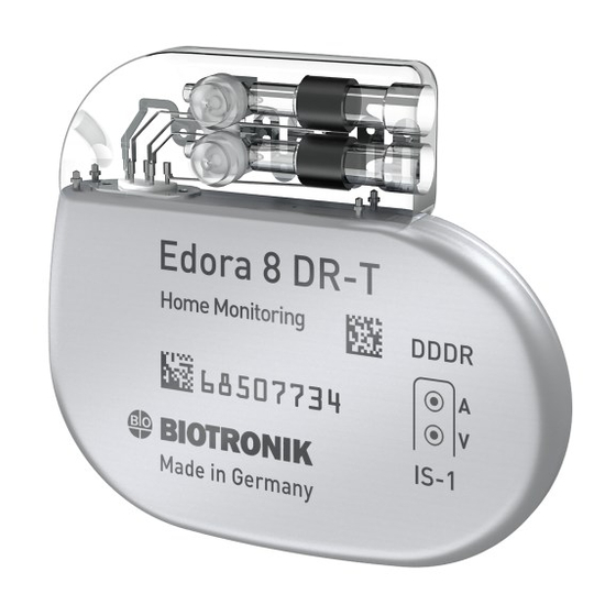
Page 7: System Overview
The ellipsoid shape facilitates ingrowth into the pectoral muscle area. The housing serves as an antipole in the case of unipolar lead configuration. Lead connections BIOTRONIK provides pacemakers with headers for different standardized lead connections: • IS‑1 •... - Page 8 Only quadripolar leads may be connected to the IS4 connector port on device type HF QP with IS4. Note Use only adapters approved by BIOTRONIK for leads with different connections. • If you have any questions concerning the compatibility of other manufacturers' leads, please contact BIOTRONIK.
- Page 9 Steroid-eluting leads reduce inflammatory processes. The fractal design of the leads allows for low pacing thresholds, high pacing impedance, and a low risk of oversensing. BIOTRONIK provides a series of adapters to connect a variety of already implanted leads to new devices.
- Page 10 With Home Monitoring, diagnostic and therapeutic information as well as technical data of the device are automatically and wirelessly sent to a transmitter via an antenna in the device header. The data is encrypted and sent from the transmitter to the BIOTRONIK Service Center via the cellular phone network.
- Page 11 Note The technical manual pertaining to the device is either included in hard copy form in the storage package or is available in digital form on the internet: https://manuals.biotronik.com Note The warranty booklet for this device is either included in hard copy form in the storage package or is available in digital form on the internet: https://www.biotronik.com/warranty-booklet...
-
Page 12: Diagnostic And Therapy Functions
Product Description Diagnostic and Therapy Functions Diagnostic and Therapy Functions General overview All the systems have extensive features that allow quick diagnosis and delivery of safe therapy for bradycardia conditions. • Automatic functions make it easy and fast to implant, configure, and check the pacemaker. •... - Page 13 Product Description Diagnostic and Therapy Functions Resynchronization therapy Triple-chamber devices have functions to configure different VV delays in order to resynchronize the ventricles. • Capture control is also available for the left ventricle with automated tracking of the pacing threshold or automatic threshold monitoring (ATM) for trend analysis. •...
-
Page 14: General Safety Instructions
General Safety Instructions General Information on Safe Handling of the Device General Safety Instructions General Information on Safe Handling of the Device Observe notes and follow instructions WARNING Risk to patient, risk to physician and interferences of device Cardiac electrotherapy is subject to specific conditions. From the transport to the storage, in terms of sterility, concerning technical complications, what requires special care during implantation or what needs to be observed regarding risky therapies with persons wearing a pacemaker: The device system is sensitive and must not be damaged, in order not to harm patients. - Page 15 General Information on Safe Handling of the Device Technical manuals Technical manuals are either included in hard copy form in the storage package or available in digital form on the internet: https://manuals.biotronik.com. Consult all relevant technical manuals. Keep the technical manuals for future reference.
-
Page 16: Operating Conditions
General Safety Instructions Operating Conditions Operating Conditions WARNING Risk to patient and interferences of device Cardiac electrotherapy is subject to special operating conditions. If these are not fulfilled, the functionality of the device may be impaired; if the functionality of the device is impaired, the patient may be at risk. -
Page 17: Possible Complications
Please take all the following safety information carefully into account. General information on medical complications Complications for patients and device systems generally recognized among practitioners also apply to BIOTRONIK devices. • It is impossible to guarantee the efficacy of antiarrhythmia therapy, even if the programs have proven successful during tests or subsequent electrophysiological studies. - Page 18 Any device can be sensitive to interference, for example, when external signals are sensed as intrinsic rhythm: • BIOTRONIK devices have been designed so that their susceptibility to EMI is minimal. • Due to the intensity and variety of EMI, there is no guarantee for safety. It is generally assumed that EMI produces only minor symptoms in patients, if any.
-
Page 19: Possible Risks
General Safety Instructions Possible Risks Possible Risks WARNING Risk to patient and interferences with the device Cardiac electrotherapy is subject to special risks. They must be considered so that the functionality of the device is not impaired and, as a result, put the patient at risk. •... - Page 20 BIOTRONIK devices with the "MR conditional" function display the identification ProMRI. Magnetic resonance imaging (MRI) should only be performed while following mandatory precautions to protect the device system and the patient.
-
Page 21: Implantation
– Triple-chamber device: an additional unipolar, bipolar, or quadripolar LV lead • Approved connections are IS-1 and IS4: Use only adapters approved by BIOTRONIK for leads with different connections or leads from other manufacturers. • BIOTRONIK blind plugs •... - Page 22 Use a replacement device. • Return the damaged device to BIOTRONIK. Peel off the sealing paper of the outer blister at the marked position in the direction of the arrow. The inner blister must not come into contact with persons who have not sterilized their hands or gloves, nor with non-sterile instruments.
- Page 23 Avoiding damage to the header Set screws must be tightened or loosened with care. • Loosen set screws with the supplied torque wrench. Use only BIOTRONIK torque wrenches! • If lead revision is necessary, re-order sterile torque wrenches from BIOTRONIK.
- Page 24 Implantation Implantation Procedure Establishing wandless telemetry The programmer must be no more than 3 m from the device; ideally there should be no obstructions between the patient and the programmer. Turn on wandless telemetry on the programmer. Apply the programming head for about 2 s until successful initialization is displayed on the programmer: „...
-
Page 25: Precautionary Measures While Programming
Implantation Precautionary Measures while Programming Precautionary Measures while Programming Caution Safety information The programming of devices requires special precautionary measures. • Please take all the following precautionary measures carefully into account. Checking the device system • After auto-initialization, perform a follow-up to see if the device system is functioning properly. •... - Page 26 Program VA criterion: The aim is to set a VA criterion that is longer than the longest measured retrograde conduction time. Preventing conduction of atrial tachycardia BIOTRONIK devices feature several functions to prevent conduction of atrial tachycardia to the ventricle(s): •...
- Page 27 Implantation Precautionary Measures while Programming If an ICD is implanted at the same time, do not permit unipolar pacing If an ICD is implanted in addition to a pacemaker and a lead failure occurs, it is possible to switch to unipolar pacing after resetting the pacemaker or using the automatic lead check.
-
Page 28: Magnet Response
Magnet response in standard program Applying a magnet or the programming head can result in an unphysiological rhythm change and asynchronous pacing. The magnet response is set as follows in the standard program of BIOTRONIK pacemakers: •... -
Page 29: Follow-Up
(in-office follow-up). • Taking into account current medical guidelines and with appropriate follow-up using BIOTRONIK Home Monitoring, subsequent in-office follow-up intervals may be extended up to 12 months for triple-chamber pacemakers and up to 24 months for single- and dual-chamber pacemakers. - Page 30 Implantation Follow-up Follow-up with the programmer Proceed as follows during an in-office follow-up: Record and evaluate the ECG. Interrogate the device. Evaluate the status and automatically measured follow-up data. Check the sensing and pacing functions. Manually perform standard tests if necessary. If applicable, evaluate statistics and IEGM recordings.
-
Page 31: Patient Information
Information for patients is written in a language understandable to laypersons. Anatomy, technology and living with an implanted device are the topics discussed here. This information is available in digital form on the internet: https://patients.biotronik.com • Request that patients contact the physician in case of uncertainties. -
Page 32: Replacement Indications
Implantation Replacement Indications Replacement Indications Possible charging status The time span from the beginning of service (BOS) to elective replacement indication (ERI) is determined by, among others, the following: • Battery capacity • Lead impedance • Pacing program • Pacing to inhibition ratio •... - Page 33 Implantation Replacement Indications Deactivated functions with ERI The following functions are deactivated: • Atrial pacing • Night program • Rate adaptation • Atrial and ventricular capture control • Rate fading • Atrial overdrive pacing • IEGM recordings • Statistics • Home Monitoring •...
-
Page 34: Explantation And Device Replacement
BIOTRONIK takes back used products for the purpose of environmentally safe disposal. • Clean the explanted device with an at least 1% sodium hypochlorite solution. • Rinse off with water. • Fill out the explantation form and send it to BIOTRONIK together with the cleaned device. -
Page 35: Parameter
Parameter Timing Parameter Note Unless described separately, information for device type HF also applies to device type HF QP. Timing Basic rate day/night Parameter Range of values Standard 60 bpm Basic rate 30 ... (5) ... 100 ... (10) ... 200 bpm 50 bpm Night rate OFF; 30 ... (5) ... 100 ... (10) ... 200 bpm Night begins 00:00 ... - Page 36 Parameter Timing Ventricular pacing Parameter Range of values Standard Ventricular pacing BiV, RV; LV Triggering OFF; RVs; RVs + PVC LV T-wave protection ON; OFF Maximum trigger rate AUTO; 90 ... (10) ... 160 bpm AUTO Initially paced chamber RV; LV VV delay after Vp 0 ...
- Page 37 Parameter Timing Ventricular pacing suppression Parameters valid for devices in DDD-ADI or DDDR-ADIR modes: Parameter Range of values Standard Vp suppression OFF; ON Pacing suppression after consecutive ventricular 1 ... (1) ... 8 sensing Pacing supported after X 1 ... (1) ... 4 (out of 8) cycles Refractory periods Parameter...
-
Page 38: Pacing And Sensing
Parameter Pacing and Sensing Pacing and Sensing Pulse amplitude and pulse width Parameter Range of values Standard Pulse amplitude 0.2 ... (0.2) ... 6.0 ... (0.5) ... 7.5 V 3.0 V A/RV/LV Pulse width A/RV/LV 0.1 ...(0.1) ... 0.5 ... (0.25) ... 1.5 ms 0.4 ms Sensitivity Parameter Range of values Standard Sensitivity AUTO;... - Page 39 Parameter Pacing and Sensing Atrial overdrive pacing Parameter Range of values Standard OFF; ON With ON: maximum overpacing rate Atrial overdrive pacing 120 bpm, mean rate increase approxi- mately 8 bpm, rate decrease after 20 cycles Lead configuration Parameter Range of values Standard Sensing polarity A Unipolar;...
- Page 40 Parameter Pacing and Sensing IEGM recordings Parameter Range of values Standard Number of recordings — (each max. 10 s) High atrial rate (HAR) OFF; AT; mode switching High ventricular rate (HVR) OFF; ON Patient trigger OFF; ON (initiated by patient) Pre-trigger recording 0;...
-
Page 41: Rate Adaptation
Parameter Rate Adaptation Rate Adaptation CLS modes: closed loop stimulation Parameter Range of values Standard Maximum CLS rate 80 ... (10) ... 160 bpm 120 bpm Very low; Low; Medium; High; CLS response Medium Very high CLS resting rate control OFF; +10 ... (10) ... +50 bpm +20 bpm Vp required Yes;... -
Page 42: Mri Program
Parameter MRI Program MRI Program MRI modes Modes valid for devices marked ProMRI: Mode Range of values Standard MRI program ON; OFF; AUTO Today's date ... (1 day) ... Expiration date Today's date + 14 days today's date + 14 days OFF; A00; V00 OFF; D00; A00; V00 Dependent on perma- MRI mode nent program... -
Page 43: Preset Programs
Parameter Preset Programs Preset Programs Standard and safe program Mode after auto-initialization: Parameter Factory setting Standard Safe program In the AAI mode, Mode VVIR the safe program is also AAI. Mode DDDR Lead configuration, automatically determined and set immediately after connection: Parameter Factory setting Standard... - Page 44 Parameter Preset Programs Parameter Factory setting Standard Safe program Pulse amplitude A 3.0 V 3.0 V — Pulse amplitude RV 3.0 V 3.0 V 4.8 V Pulse amplitude LV 3.0 V 3.0 V — Pulse width A 0.4 ms 0.4 ms — Pulse width RV 0.4 ms 0.4 ms 1.0 ms Pulse width LV 0.4 ms 0.4 ms — Sensitivity A AUTO AUTO —...
-
Page 45: Tolerances Of Parameter Values
Parameter Tolerances of Parameter Values Tolerances of Parameter Values Parameter Range of values Tolerance 30 ... (5) ... 100 ... (10) ... Basic rate ± 20 ms 200 bpm Basic interval 1000 ms ± 20 ms Magnet rate (magnet interval) 90 bpm (664 ms) ± 20 ms Pulse amplitude 0.2 ... 7.5 V The greater value of ±... -
Page 46: Technical Data
X-ray identification All device types receive the BIOTRONIK logo for X-ray identification. It can be found centrally between the circuitry and the battery inside of the housing and is visible in an X-ray image. -
Page 47: Electrical Characteristics
The pulse amplitude reaches its maximum value at the beginning of the pulse (Ua). With increasing pacing duration (tb), the pulse amplitude is reduced dependent on the pacing impedance. Resistance to interference All variants of BIOTRONIK devices comply with the requirements of EN 45502-2-1: 2003, Section 27.5.1 at the highest sensitivity. -
Page 48: Battery Data
Technical Data Battery Data Battery Data Battery characteristics The following data is provided by the manufacturers: Manufacturer Greatbatch Ltd. LITRONIK Batterietechnologie GmbH 10000 Wehrle Drive Birkwitzer Strasse 79 Clarence, NY, 14031, USA 01796 Pirna, Germany Battery type GB 3193 LiS 2650MK LiS 3150MK ® System Li-Mn0 Li-Mn0 Li‑CFX/SVO Device type... - Page 49 Technical Data Battery Data Mean service times SR For single-chamber devices the following times result when set to AAIR or VVIR, with a basic rate of 60 bpm and a pulse width of 0.4 ms at an impedance of 500 Ω: Amplitude Pacing Average service time 100%...
-
Page 50: Legend For The Label
Do not resterilize Single use only. Do not reuse! Do not use if packaging is damaged and consult the technical manual Transmitter with non-ionizing radiation at designated frequency MR conditional Compabiltiy with telemetry protocol version 2 of BIOTRONIK Home Monitoring... - Page 51 Technical Data Legend for the Label Implanted device Torque wrench IS-1 Uncoated device: NBG code and compatible leads VVIR/AAIR Example Examples of the header configuration: IS-1, IS-1/ Shipping setting: Pulse Shipping setting: Sensitivity amplitude and pulse width Shipping setting: AV delay Shipping setting: VV delay Scannable QR code...
Need help?
Do you have a question about the Edora 8 SR-T and is the answer not in the manual?
Questions and answers