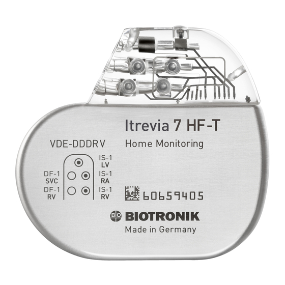
BIOTRONIK Ilesto 5 VR-T Technical Manual

BIOTRONIK Ilesto 5 VR-T Technical Manual

Tachyarrhythmia therapy / cardiac resynchronization therapy

Advertisement

Ilesto
xxx
xxx
xxx
ICD Familie • Tachyarrhythmietherapie • Kardiale Resynchronisationstherapie
xxx
xxx
xxx
xxx
xxx
xxx
xxx
xxx
Technical Manual
Technická příručka
Brugermanual
Gebrauchsanweisung
Manual técnico
Käyttöohje
Manuel technique
Manuale tecnico di istruzione
Gebruikshandleiding
Instrukcja obsługi
Manual técnico
Bruksanvisning
• en
• cs
• da
• de
• es
• fi
• fr
• it
• nl
• pl
• pt
• sv

Advertisement

Table of Contents
loading
Need help?

Need help?

Do you have a question about the Ilesto 5 VR-T and is the answer not in the manual?

Questions and answers

Subscribe to Our Youtube Channel

Summary of Contents for BIOTRONIK Ilesto 5 VR-T

  • Page 1 Ilesto Technical Manual • en Technická příručka • cs Brugermanual • da ICD Familie • Tachyarrhythmietherapie • Kardiale Resynchronisationstherapie Gebrauchsanweisung • de Manual técnico • es Käyttöohje • fi Manuel technique • fr Manuale tecnico di istruzione • it Gebruikshandleiding •...
  • Page 2 All rights reserved. Specifications subject to modification, revision and improvement. ® BIOTRONIK Home Monitoring, IEGM-Online HD and SMART Detecton are registered trademarks of BIOTRONIK SE & Co. KG 0123 0681 2012 12-D-xx Revision: B (2012-xx-xx) BIOTRONIK SE & Co. KG Woermannkehre 1 12359 Berlin ·...
  • Page 3 Ilesto 5/7 VR-T, VR-T DX, DR-T, HF-T ICD Family Tachyarrhythmia Therapy Cardiac Resynchronization Therapy Technical Manual for the Device Doc. Id.: GA-HW_en--mul_393468-B Index GA-HW_en--mul_393468-BTechnical[nbsp ]Manual for the[nbsp ]DeviceIlesto 5/7 VR-T, VR-T DX, DR-T, HF-T...
  • Page 5: Table Of Contents

    Table of Contents Table of Contents Table of Contents Product Description..........5 Intended Medical Use .
  • Page 6 Table of Contents...
  • Page 7: Product Description

    Product Description Product Description Product Description1GA-HW_en--mul_393468-BTechnical[nbsp ]Manual for the[nbsp ]DeviceIlesto 5/7 VR-T, VR-T DX, DR-T, HF-T Intended Medical Use Intended use Ilesto 5/7 is part of a familiy of implantable cardioverter-defibrillators (ICDs). Primary objective of the therapy is to prevent sudden cardiac death. Furthermore, the device is capable of treating bradycardia arrhythmias and cardiac resynchroni- zation therapy with multisite ventricular pacing.
  • Page 8 Ilesto can treat life-threatening ventricular arrhythmias with antitachycardia pacing and defibrillation. Generally approved differential diagnostics methods, indications, and recommen- dations for ICD therapy apply to BIOTRONIK devices. See the guidelines of cardi- ology associations for guidance. We recommend observing the indications published by the German Cardiac Society (Deutsche Gesellschaft für Kardiologie, Herz- und Kreislaufforschung) and the...
  • Page 9: System Overview

    The housing serves as a potential antipole during shock delivery or in the case of unipolar lead configuration. DF-1/IS-1 or DF4/IS-1 BIOTRONIK provides ICDs with headers for different standardized lead connec- tions: DF-1/IS-1 and DF4/IS-1. Note: The device type DX can only be connected using a DF-1/IS-1 connector.
  • Page 10 Telemetric communication between the device and the programmer can be carried out following initialization either by applying the programming head (PGH) to the device or by using radio frequency (RF) telemetry in the programmer. BIOTRONIK ® calls this function SafeSync...
  • Page 11 Product Description NBD and NBG codes VVE is the NBD code for the antitachycardia mode of the single-chamber, dual- chamber, and triple-chamber devices: Shock in the ventricle Antitachycardia pacing (ATP) in the ventricle Detection via IEGM analysis DDDR is the NBG code for the antibradycardia mode of the dual-chamber device: Pacing in the atrium and ventricle Sensing in the atrium and ventricle Pulse inhibition and pulse triggering...
  • Page 12 Product Description BIOTRONIK In addition to effective pacing therapy, BIOTRONIK provides a complete therapy ® Home Monitoring management system: • With Home Monitoring, diagnostic and therapeutic information as well as tech- nical data are automatically sent to a stationary or mobile transmitter via an antenna in the device header.
  • Page 13: Therapeutic And Diagnostic Functions

    Product Description Therapeutic and Diagnostic Functions Diagnostic functions • Data from implantation and the most recent interrogations and follow-ups are recorded as well as arrhythmia episodes; they are stored together with other data to assess patients and the state of the device at any time. •...
  • Page 14 Product Description Storing programs The parameter settings can be saved in 3 individual therapy programs. Home Monitoring functions • The device automatically sends information to the transmitter once a day. It also sends messages related to events, which are immediately forwarded to the Service Center.
  • Page 15: General Safety Instructions

    General Safety Instructions General Safety Instructions General Safety Instructions2GA-HW_en--mul_393468-BTechnical[nbsp ]Manual for the[nbsp ]DeviceIlesto 5/7 VR-T, VR-T DX, DR-T, HF-T Operating Conditions Care during shipping and • Devices are not to be stored or transported close to magnets or sources of storage electromagnetic interference.
  • Page 16: Possible Complications

    (EMI) intrinsic rhythm or if measurements prevent rate adaptation. • BIOTRONIK devices have been designed so that their susceptibility to EMI is minimal. • Due to the intensity and variety of EMI, there is no guarantee for safety. It is generally assumed that EMI produces only minor symptoms, if any, in patients.
  • Page 17: Possible Risks

    • Adhere to instructions for risky therapy and diagnosis procedures. • Shield device against radiation. • After applying radiation, double-check the device system to make sure it is functioning properly. Note: Please contact BIOTRONIK with questions during the risk/benefit analysis.
  • Page 18 General Safety Instructions Magnetic resonance Magnetic resonance imaging (MRI) is contraindicated due to the high frequency imaging fields and the associated magnetic flux density: damage or destruction of the device system by strong magnetic interaction and damage to the patient by exces- sive warming of the body tissue in the area surrounding the device system.
  • Page 19: Implantation

    • DF-1, DF4 and IS-1 connections are approved. For leads with a different con- nection or leads from other manufacturers, use adapters approved by BIO- TRONIK only. • BIOTRONIK programmer (with integrated SafeSync RF telemetry or with sepa- rate SafeSync Module) and approved cable • External multi-channel ECG device •...
  • Page 20 There is a blind plug for DF-1 and IS-1 connections in the header. The provided set header screws must be carefully loosened or tightened. • Loosen set screws with the supplied screwdriver. Use only BIOTRONIK screw- drivers with torque control! • Do not forcibly pull out the blind plug! •...
  • Page 21 Implantation Connecting the lead connector to the device Disconnect stylets and stylet guides. DF-1/IS-1 connection: • Connect the DF-1 connector for the right-ventricular shock coil to RV. • Connect the DF-1 connector for the supraventricular shock coil to SVC. Or connect a subcutaneous array to SVC. DF4/IS-1 connection: •...
  • Page 22 Implantation Implanting Prepare the vein. Implant the leads, perform the measurements, and fixate the leads. Form the device pocket. Connect the lead connector to the device. Insert the device. Guide the fixation suture through the opening in the header and fixate the device in the prepared device pocket.
  • Page 23: Precautionary Measures While Programming

    Manually set parameters can be unsafe. For example, unsuitable far-field protec- tion may impede sensing of intrinsic pulses. • Note automatic sensitivity control. Preventing device-induced BIOTRONIK devices feature several functions to prevent device-induced complica- complications tions to the greatest extent possible: • Measure the retrograde conduction time.
  • Page 24 Implantation Preventing conduction of BIOTRONIK devices feature several functions to prevent conduction of atrial tachy- atrial tachycardia cardia to the ventricle(s): • Set mode switching for indicated patients. • Set the upper rate and the refractory periods to prevent abrupt ventricular rate switching.
  • Page 25 Implantation Considering power RF telemetry requires somewhat more power: Consumption during implantation consumption and service corresponds to approximately 10 days of service time and consumption during a time 20-minute follow-up corresponds to approximately 3 days. • Do not establish unnecessary RF telemetry. •...
  • Page 26: Magnet Response

    • If detection interruptions of longer than 8 hours are required, the magnet has to be briefly removed from the device. The 8 hour countdown restarts when the magnet is applied again. • Use BIOTRONIK magnets: type M-50 permanent magnets.
  • Page 27: Follow-Up

    • The next in-office follow-up should be carried out once a year and no later than 12 months after the last in-office follow-up. Follow-up with BIOTRONIK Monitoring using the Home Monitoring function does not serve to replace regular ®...
  • Page 28: Patient Information

    Implantation Patient Information Patient ID card A patient ID card is included in delivery. • Provide the patient with the patient ID. • Request that patients contact the physician in case of uncertainties. Prohibitory signs Places with prohibitory signs must be avoided. •...
  • Page 29: Replacement Indications

    Implantation Replacement Indications Possible battery levels • BOS: Beginning of Service: > 70% charge • MOS 1: Middle of Service: 70% to 40% residual charge • MOS 2: Middle of Service: < 40% residual charge • ERI: Elective Replacement Indication, (i.e. RRT: Recommended Replacement Time) •...
  • Page 30: Explantation And Device Replacement

    Devices should not be cremated. • Explant the device before the cremation of a deceased patient. Disposal BIOTRONIK takes back used products for the purpose of environmentally safe dis- posal. • Clean the explant with an at least 1% sodium hypochlorite solution.
  • Page 31: Parameters

    Parameters Parameters Parameters4GA-HW_en--mul_393468-BTechnical[nbsp ]Manual for the[nbsp ]DeviceIlesto 5/7 VR-T, VR-T DX, DR-T, HF-T Bradycardia / CRT General ICD therapy Parameter Range of values Standard ICD therapy OFF; ON Programs Display standard program; Display – safe program; Display first interro- gated program; Individual 1,2,3 Timing: Basic rate day/ night and rate hystereses Parameter...
  • Page 32 Parameters Timing: AV delay Parameter Range of values Standard AV dynamics Low; Medium; High; Fixed; (Individual) AV delay (1 or 2) after: – Pacing 15; 40 ... (5) ... 350 ms – – Sensing Either automatic: AV delay after pacing –...
  • Page 33 Parameters Timing: Mode switching Parameter Range of values Standard Intervention rate OFF; 120 ... (10) ... 200 bpm 160 bpm Onset criterion 3 ... (1) ... 8 (out of 8) Resolution criterion Modification of basic rate OFF; 5 ... (5) ... 30 bpm 10 bpm Mode VDI(R);...
  • Page 34 Parameters Timing: Rate adaptation via accelerometer Parameter Range of values Standard Maximum sensor rate 80 ... (10) ... 160 bpm 160 bpm Sensor gain AUTO Medium Very low; Low; Medium; High; Very high Sensor threshold Very low; Low; Medium; High; Medium Very high Rate increase...
  • Page 35: Tachycardia

    Parameters Tachycardia Detection Parameter Range of values Standard Interval AT/AF 240 ... 600 ms 300 ms Interval VT1 OFF; 270 ... (10) ... 600 ms Interval VT2 OFF; 270 ... (10) ... 500 ms Interval VF OFF; 240 ... (10) ... 400 ms 300 ms Detection counter VT1 10 ...
  • Page 36 Parameters Therapy: Shock Parameter Range of values Standard Number of shocks VT1/VT2 0; 1; 2; 6; 8 Number of shocks VF 6; 8 1. Shock for VT1/VT2 40 J 2 ... (2) ... 20 ... (5) ... 40 J 2. Shock for VT1/VT2 40 J 4 ...
  • Page 37: Sensing

    Parameters Sensing Sensitivity and thresholds Parameter Range of values Standard Sensing A STD; OFF; IND Sensing RV STD; TWS; VFS; IND Sensing LV STD; OFF; IND Upper threshold RV 50; 75 % Upper threshold LV 50; 75 % Upper threshold duration 110;...
  • Page 38: Diagnostics

    Parameters Diagnostics The following can be set: Parameter Range of values Standard For AT/AF OFF; ON For Ilesto 7: Extended ON For SVT OFF; ON Periodic recording When Home Monitoring OFF: 90 days OFF; 30 ... (30) ... 180 days IEGM configuration RA, RV, LV RA, RV, LV...
  • Page 39: Home Monitoring

    Parameters Home Monitoring Parameter Range of values Standard Home Monitoring OFF; ON Time of transmission STD; 00:00 ... (01:00) ... 23:00 hh:mm IEGM for: – Therapy episodes OFF; ON – Monitoring episodes Ongoing atrial episode OFF; 6, 12, 18 h 12 h...
  • Page 40 Parameters...
  • Page 41: Technical Data

    Technical Data Technical Data Technical Data5GA-HW_en--mul_393468-BTechnical[nbsp ]Manual for the[nbsp ]DeviceIlesto 5/7 VR-T, VR-T DX, DR-T, HF-T Mechanical Characteristics Housing Devices with a DF-1/IS-1 header: Type Connection W x H x D in mm Volume in Mass in g VR, DX, DR DF-1 65 x 55 x 11 DF-1...
  • Page 42: Electrical Characteristics

    • Nominal carrier frequency: 403.6 MHz • Maximum power of transmission: < 25 µW (-16 dBm) International radio certifi- ® Devices with BIOTRONIK Home Monitoring are equipped with an antenna for cation wireless communication. Telemetry data for Canada and the USA:...
  • Page 43 Technical Data Resistance to interference • Note on device type DX (only devices with a DF-1/IS-1 connection): The EMC requirements are met as long as atrial sensitivity is set to 1.0 mV (factory set- tings) or values ≥ 1.0 mV. Measures must be taken to assure interference-free therapy if more sensitive values are set.
  • Page 44: Battery Data

    Calculation of the number of shocks: Longevity [in years] x number of shocks per of shocks year Ilesto 5 VR-T Service times with GB 2992 or LiS 3410 RA battery: Longevity [in years] at number of shocks per year Stimulation 10.42...
  • Page 45 Technical Data Ilesto 5 VR-T DX Service times with GB 2992 or LiS 3410 RA battery: Longevity [in years] at number of shocks per year Stimulation 9.48 7.76 6.57 5.70 5.03 9.24 7.61 6.46 5.61 4.96 8.75 7.26 6.21 5.42 4.81...
  • Page 46 Technical Data Ilesto 7 DR-T Service times with GB 2992 battery: Longevity [in years] at number of shocks per year Stimulation 10.73 8.82 7.48 6.50 5.74 10.22 8.47 7.23 6.31 5.59 9.20 7.76 6.70 5.90 5.27 100% 8.05 6.92 6.07 5.40 4.87 Ilesto 7 HF-T...
  • Page 47: Legend For The Label

    Technical Data Legend for the Label Label on the package The label icons symbolize the following: Manufacturing date Use by Temperature limit Order number Serial number Product identification number Dangerous voltages! CE mark Contents Follow the instructions for use Sterilized with ethylene oxide Do not resterilize Do not reuse STERILIZE...
  • Page 48 Technical Data Bipolar IS-1 connector Unipolar IS-1 connector Unipolar DF-1 connector DF4 connector...

This manual is also suitable for:

Icd seriesIlesto 5 vr-t dxIlesto 5 hf-tIlesto 7 vr-tIlesto 5 dr-tIlesto 7 vr-t dx ... Show all

Table of Contents