Table of Contents
Advertisement
Quick Links
Programmer's Guide
ObjectC 100 I/O
ObjectC 100 CAN
ObjectC 100 RS485
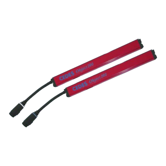
Multiple Proximity Switch systems
for object recognition
English
Deutsch
Multiple Proximity Switch systems
for object recognition: Measurement light curtain
system to measure the dimensions of objects
quickly and reliably
IMPORTANT NOTICE
FOLLOW THE INSTRUCTIONS GIVEN IN THIS MANUAL CAREFULLY. FAILURE TO DO
SO MAY CAUSE CUSTOMER COMPLAINTS AND SERIOUS CALL BACKS. KEEP
INSTRUCTION MANUAL ON SITE.
OBJECTC-100 / OBJECT100 SYSTEMS ARE NOT SAFETY SYSTEMS! THIS MEANS
THAT ANY USE FOR THE PROTECTION OF PEOPLE IS FORBIDDEN.
© CEDES Safety & Automation AG
Oct 2009 Vers 1.022
http://csa.cedes.com/
Part No. 105 828 E
Advertisement
Table of Contents

Subscribe to Our Youtube Channel
Summary of Contents for Cedes ObjectC 100 I/O
-
Page 1: Important Notice
INSTRUCTION MANUAL ON SITE. OBJECTC-100 / OBJECT100 SYSTEMS ARE NOT SAFETY SYSTEMS! THIS MEANS THAT ANY USE FOR THE PROTECTION OF PEOPLE IS FORBIDDEN. © CEDES Safety & Automation AG Oct 2009 Vers 1.022 http://csa.cedes.com/ Part No. 105 828 E... -
Page 2: Table Of Contents
RS485 communication example 1 ....21 3.1.4. Timing (RS485)...........22 3.2. Master programming (RS485)......23 3.3. Technical data RS485........23 4. Advanced Features ........23 4.1. Light curtain design ........23 4.2. Beam counting direction ......24 4.3. Measurement reference point.......25 © CEDES Safety & Automation AG http://csa.cedes.com/... -
Page 3: Introduction
CANopen network. Please contact your nearest overheight (i.e. object is too tall) and overhang. The CEDES dealer for more information. ObjectC 100 I/O controller offers four aditional 2.2. CAN Standard mode outputs to monitor single beams or groups of beams (zones). -
Page 4: Spontaneous Telegram (Can)
Therefore there are no spontaneous telegrams for this type. The extended CAN mode offers the feature of spontaneous telegrams 65 [41 Hex] (State zone X- axis) and 67 [43 Hex] (State zone Y-axis). Chapter 2.3 describes this feature. © CEDES Safety & Automation AG http://csa.cedes.com/... -
Page 5: Commands And Responses (Can / Rs485)
43 Hex State sector Y-axis 65 Hex Beam status with light curtain status* Response data Data Byte 3-8 Available only in the extended CAN mode Available in the extended CAN mode and RS485 © CEDES Safety & Automation AG http://csa.cedes.com/... -
Page 6: Light Curtain Status (Spontaneous Response)
The pseudo-command serves merely to allow the controller to respond to the PLC. Table 9: Command 02 Hex Command 2 [02 Hex] Response 3 [03 Hex] Value Value (not used) 0 - 7 (Not used) Byte 3 - 8 Byte 3 - 8 © CEDES Safety & Automation AG http://csa.cedes.com/... -
Page 7: Get Status Controller (04 [04 Hex])
Permanent scan standard active Permanent scan w. overhang not active Permanent scan w. overhang active Not used Byte 4-8 * This command delays the response times according Operation manual (Part No. 104 906 Chapter 11.2) © CEDES Safety & Automation AG http://csa.cedes.com/... -
Page 8: Get Number Of Beams (18 [12 Hex])
Sending command 22 anew, before sending command 24, will reset the scan counter and reset the status values noted in command 24 (see 2.2.5.9) Table 15: Command 16 Hex Command 22 [16 Hex] Response 23 [17 Hex] Value Value Not used Not used Byte 3 - 8 Byte 3-8 © CEDES Safety & Automation AG http://csa.cedes.com/... -
Page 9: Stop Permanent Standard Scan (24 [18 Hex])
Byte 3 0-255 Value Not used Byte 4 Byte 4 -8 Not used Byte 5 - 8 * This command delays the response times according Operation manual (Part No. 104 906 Chapter 11.2) © CEDES Safety & Automation AG http://csa.cedes.com/... - Page 10 9600 Baud 57600 Baud 4),5) Periodic mode Periodic mode inactive Measuring mode Single or Periodic 1 .. 254 Periodic mode active with (see Par 83) time constant t = n x 13.1 ms © CEDES Safety & Automation AG http://csa.cedes.com/...
-
Page 11: Set Default Configuration (30 [1E Hex])
35 (see 2.2.5.14). Table 21: Command 20 Hex Command 32 [20 Hex] Response 33 [21 Hex] Value Value Not used Not used Byte 3 - 8 Byte 3 - 8 © CEDES Safety & Automation AG http://csa.cedes.com/... -
Page 12: Stop Permanent Scan With Overhang Monitoring (34 [22 Hex])
Number of scans (LSB) Byte 3 - 8 Byte 3 0-255 Number of scans Byte 4 0-255 Number of scans Byte 5 0-255 Number of scans (MSB) Byte 6 Not used Byte 7 - 8 © CEDES Safety & Automation AG http://csa.cedes.com/... -
Page 13: Get Beam Status (38 [26 Hex])
Not used Byte 4 - 8 Byte 4 - 8 * This command delays the response times according Operation manual (Part No. 104 906 Chapter 11.2) Note: Beam numbers for a zone are inclusive © CEDES Safety & Automation AG http://csa.cedes.com/... -
Page 14: Restart (44 [2C Hex])
The extended CAN mode offers the additional command "State sector X-axis (64 [40 Hex])" and "State Sector Y- axis (66 [42 Hex])" as well as parameters for different properties of these commands. © CEDES Safety & Automation AG http://csa.cedes.com/... -
Page 15: Boot-Up Message
Remark: Id(Std): see Table 33 Table 36: Response 2 Id (STD) Byte 1 Byte 2 Byte 3 Byte 4 Byte 5 Byte 6 Byte 7 Byte 8 [000005E4 Hex] [08 Hex] Remark: Id(Std): see Table 34 © CEDES Safety & Automation AG http://csa.cedes.com/... -
Page 16: Can Addresses In The Extended Can Mode
1: Sector interrupted Zone X24 Zone X25 0: Sector not interrupted Byte 8 1: Sector interrupted Zone X32 • This command delays the response times according Operation manual (Part No. 104 906 Chapter 11.2) © CEDES Safety & Automation AG http://csa.cedes.com/... -
Page 17: State Sector Y-Axis (66 [42 Hex])
5 seconds. This can overload the CAN network communication. Parameter 82 [52 Hex] (Table 19) offers the limitation of data transfer. © CEDES Safety & Automation AG http://csa.cedes.com/... -
Page 18: Periodic Mode
T1, T2, T3, T4, T5 etc. ). It lends itself for applications to determine the length or the profile of goods (G1). For object G1, according to Figure 4, passing the light curtain with a constant speed, the length is calculated as: © CEDES Safety & Automation AG http://csa.cedes.com/... -
Page 19: Period Duration
It is strongly recommended that the y-axis section of the light curtain is set up vertically to avoid confusion with results. © CEDES Safety & Automation AG http://csa.cedes.com/... -
Page 20: Example
(1.5 m = 60 beams, pitch 25 mm) With this configuration, the ObjectC°100 sends a command at every interruption of the light curtain. Example: The operator picks from the 5 tray (X-axis) of the 3 row (Y-axis). © CEDES Safety & Automation AG http://csa.cedes.com/... -
Page 21: Objectc 100 Rs485
0000 0000 03 Hex 0000 0011 The responses to be expected from an ObjectC 100 RS485 system with a light curtain counting 30 beams (=1E Hex), and no offset beams, are as follows: © CEDES Safety & Automation AG http://csa.cedes.com/... -
Page 22: Timing (Rs485)
= 5 ms. When using a light curtain with 254 beams and the command ‘trigger standard scan’, the time will increase to approx. t = 55 ms. 11 bytes = 4.583 ms response © CEDES Safety & Automation AG http://csa.cedes.com/... -
Page 23: Master Programming (Rs485)
• Standard and reverse beam counting mode: Chapter 4.2, Figure 10 • Blanked beams: Chapter 4.7 • Zone monitoring: Chapter 4.8 • Overheight monitoring: Chapter 4.9 • Overhang monitoring: Chapter 4.10 © CEDES Safety & Automation AG http://csa.cedes.com/... -
Page 24: Beam Counting Direction
Number of blanked beams from the end of the evaluation process monitoring field Overheight Beams which when interrupted, "oh" Lowest beam of the Overheight zone (incl.) cause the Overheight output to be activated © CEDES Safety & Automation AG http://csa.cedes.com/... -
Page 25: Measurement Reference Point
[mm] with respect to the reference point at the end of the light curtain housing Beam offset Beam number Pitch Examples: Object100 with pitch = 10 mm (Standard beam counting direction) = 5 mm = 10 mm [mm] © CEDES Safety & Automation AG http://csa.cedes.com/... -
Page 26: Measurement Accuracy
So that an object is detected definitely, the aperture has to be covered fully for the minimum measurement time . The minimum measurement time depends on the light curtain length, i.e. the number of optical elements. © CEDES Safety & Automation AG http://csa.cedes.com/... -
Page 27: Blanked Beams
Figure 13: An object with length l is detected by optical beams from the 3 x 8 mm apertures. Example (with controller ObjectC 100 I/O): An object with a 50 mm width passes through the monitoring field across the light curtain axis. The light curtain has a length of 500 mm and a pitch of 25 mm. - Page 28 I/O controller has 4 digital outputs, one representing the status for each of the 4 zones. ObjectC°100°CAN and RS485 do not offer zone monitoring, but beam information can be determined using the communication telegram "Get zone status (40 [28 Hex]". © CEDES Safety & Automation AG http://csa.cedes.com/...
-
Page 29: Overheight Monitoring
Goods, which hang over the front or back edge of a pallet, may cause obstructions or damage during the transport or storage process. The ObjectC 100 detects overhangs with one of the two following modes. © CEDES Safety & Automation AG http://csa.cedes.com/... -
Page 30: 4.10.1. Overhang Monitoring With Time Delay
The minimum overhang output signal duration "t_out" may also be adjusted, with the aid of Pot 2. t_ot Allowed Overhang duration Figure 18: Example no Overhang t_ot Allowed Overhang duration t_out Minimum output duration Figure 19: Example Overhang front side © CEDES Safety & Automation AG http://csa.cedes.com/... -
Page 31: 4.10.2. Overhang Monitoring With External Sensors
Special attention needs to be paid to carriers with openings, e.g. pallets. ▪ ObjectC 100 I/O: DIP switch S1 (7) has to be turned "OFF" (= 0) ▪ Output logic can be inverted (see chapter 2.2.5.11), default = active "Low"... -
Page 32: Trigger And Hold
Table 19. The default values can be reset with DIP switch S1 (8). See chapter 8.4.2 in the operation manual. Table 53: DIP switch S2 default setting DIP switch S2 Remarks 0 = "OFF" (DIP 1-4) See Chapter 6.4 in Operation Manual © CEDES Safety & Automation AG http://csa.cedes.com/...
Need help?
Do you have a question about the ObjectC 100 I/O and is the answer not in the manual?
Questions and answers