
Related Manuals for Del Medical CM Series


Summary of Contents for Del Medical CM Series
- Page 1 CM Series X-Ray Generator Installation & Service Manual P/N 8000-CMIS Revision: B, January 22, 2008...
- Page 2 CPI CMP 200 SERIES X-RAY GENERATOR CMP 200 MENU AEC mAs mA/ms AEC FIELD SMALL LARGE FOCAL MODE SPOT TABLE NON- WALL AUX 1 AUX 2 PREP EXPOSE BUCKY BUCKY BUCKY CMP200_001A.CDR SERVICE MANUAL PREPARED BY: COMMUNICATIONS & POWER INDUSTRIES CANADA INC. 45 RIVER DRIVE GEORGETOWN, ONTARIO, CANADA L7G 2J4 TELEPHONE: (905) 877-0161...
-
Page 3: Table Of Contents
CPI Canada Inc. PRE-INSTALLATION CMP 200 INSTALLATION SERVICE AND INSTALLATION INTERFACING, PROGRAMMING, AND CALIBRATION MANUAL P/N 740986-00 ACCEPTANCE TESTING TROUBLESHOOTING REGULAR MAINTENANCE THEORY OF OPERATION SPARES SCHEMATICS The original version of this manual (June 17, 2001) has been drafted in the English language by: Communications &... - Page 4 CPI Canada Inc. PROPRIETARY AND CONFIDENTIAL The design and information contained in this document is proprietary to Communications & Power Industries Canada Inc. (CPI), has been designed and developed at private expense, and is the exclusive property of CPI. information contained herein is loaned in confidence solely for the installation, operation, and maintenance of CPI equipment.
- Page 5 CPI Canada Inc. Pre-installation CHAPTER 1 PRE-INSTALLATION CONTENTS: Section Title 1.1.0 INTRODUCTION ............................1-2 1.1.1 Generator Description ..........................1-2 1.1.2 Features ..............................1-2 1.1.3 Radiographic Performance........................1-2 1.1.4 Environmental Specifications ........................1-3 1.1.5 Applicable Standards ..........................1-3 1.1.6 Electromagnetic Compatibility (EMC) ....................... 1-7 1.1.7 RoHS Compliance.............................
-
Page 6: Introduction
Pre-installation CPI Canada Inc. 1.1.0 INTRODUCTION This chapter summarizes the main features of the CMP 200 X-ray generator (performance, regulatory and compatibility). Safety information is provided, along with environmental, room, and installation requirements. This chapter concludes with a pre-installation checklist and a diagram showing the major component layout. -
Page 7: Environmental Specifications
CPI Canada Inc. Pre-installation 1.1.4 Environmental Specifications OPERATING 10 to 40 °C (50 to 104 °F). Ambient temperature range Relative humidity 20 to 80%, non-condensing. Altitude Sea-level to 2440 meters (700 to 1100 hPa). TRANSPORT AND STORAGE -25 to 70 °C (-13 to 158 °F).. Ambient temperature range Relative humidity 5 to 95%, non-condensing. - Page 8 Pre-installation CPI Canada Inc. EMC (EN 60601-1-2:2001/IEC 60601-1-2:2001) Guidance and manufacturer’s declaration – electromagnetic emissions The VZW2556 series of X-ray generators is intended for use in the electromagnetic environment specified below. The customer or the user of the VZW2556 series should assure that it is used in such an environment. Emissions test Compliance Electromagnetic environment - guidance...
- Page 9 CPI Canada Inc. Pre-installation 1.1.5 Applicable Standards (Cont) Guidance and manufacturer’s declaration – electromagnetic immunity The VZW2556 series of X-ray generators is intended for use in the electromagnetic environment specified below. The customer or the user of the VZW2556 series should assure that it is used in such an environment. Immunity IEC 60601 Compliance...
- Page 10 Pre-installation CPI Canada Inc. 1.1.5 Applicable Standards (Cont) Guidance and manufacturer’s declaration – electromagnetic immunity The VZW2556 series of X-ray generators is intended for use in the electromagnetic environment specified below. The customer or the user of the VZW2556 series should assure that it is used in such an environment. Immunity IEC 60601 Compliance...
-
Page 11: Electromagnetic Compatibility (Emc)
CPI Canada Inc. Pre-installation 1.1.6 Electromagnetic Compatibility (EMC) In accordance with the intended use, some models of this series of X-ray generators comply with the European Council Directive concerning Medical Devices. The CE marking affixed to compliant products signifies this. One of the harmonized standards of this Directive defines the permitted levels of electromagnetic emission from this equipment and its required immunity from the electromagnetic emissions of other devices. -
Page 12: Safety
Pre-installation CPI Canada Inc. 1.2.0 SAFETY 1.2.1 Safety and Warning Symbols The following advisory symbols are used on the safety warning labels, and/or on circuit boards, and/or on the operator console. High voltage symbol used to indicate the presence of high voltage. - Page 13 CPI Canada Inc. Pre-installation 1.2.2 Safety Notices and Warnings (Cont) X-ray radiation exposure may be damaging to health, with some effects being cumulative and extending over periods of many months or even years. Operators and service personnel should avoid any exposure to the primary beam and take protective measures to safeguard against scatter radiation.
-
Page 14: Safety Warning Labels
Pre-installation CPI Canada Inc. 1.2.2 Safety Notices and Warnings (Cont) WARNING: HAZARDOUS VOLTAGES EXIST INSIDE THE GENERATOR WHENEVER THE MAIN POWER DISCONNECT IS SWITCHED ON. THESE AREAS INCLUDE, BUT ARE NOT LIMITED TO, THE MAIN FUSE HOLDER AND ASSOCIATED CIRCUITS ON THE H.V. AUXILIARY BOARD, THE AUXILIARY AND / OR TOUCHSCREEN TRANSFORMERS, AND THE MAIN POWER CONTACTOR. - Page 15 CPI Canada Inc. Pre-installation 1.2.3 Safety Warning Labels (Cont) Weight Label This label is attached to the main generator cabinet and to the HT tank, and states the approximate weight of the main cabinet with the HT tank, and the weight of the HT tank separately. Do not attempt to lift these items without proper assistance.
- Page 16 Pre-installation CPI Canada Inc. 1.2.3 Safety Warning Labels (Cont) Caution HV Behind Cover Label This label is attached to the outside of the generator cabinet, to the cover over the inverter assembly, and to the cover in front of the touchscreen fusing board. Mains voltage is present inside the cabinet whenever the main disconnect is switched on.
- Page 17 CPI Canada Inc. Pre-installation 1.2.3 Safety Warning Labels (Cont) Danger High Tension Notice This notice is printed on the HT tank lid. High voltage may be present at the primary terminals on the tank lid board, at the output high voltage connectors, and at the mA/mAs measuring jacks if the shorting link is opened for mA/mAs measurements.
- Page 18 Pre-installation CPI Canada Inc. 1.2.3 Safety Warning Labels (Cont) HIGH VOLTAGE HAZARD: Approximately 400 VAC is present on the console board in the area of T1, C36, and J5. This is a high voltage source for the fluorescent backlight on the LCD display.
-
Page 19: Preparing For Installation
CPI Canada Inc. Pre-installation 1.3.0 PREPARING FOR INSTALLATION 1.3.1 Generator Heat Output The maximum heat output of the main generator cabinet is less than 1000 BTU / hour in normal clinical use, with a maximum of 70 BTU / hour heat output for the console. The console is primarily conduction cooled, and the main cabinet is fan cooled. - Page 20 Pre-installation CPI Canada Inc. 1.3.2 Generator Power Requirements (Cont) The table below depicts the power requirements for the 40 kW CMP 200 X-ray generators. Line Voltage 208 VAC - 5% to 230 VAC + 10%, 1 phase. 208 VAC - 5% to 230 VAC + 10%, 3 phase. 400 VAC ±...
- Page 21 CPI Canada Inc. Pre-installation 1.3.2 Generator Power Requirements (Cont) The following table defines the power line requirements for the generators. NOTE: THE FOLLOWING TABLE CONTAINS RECOMMENDED VALUES FOR THE WIRE SIZES BETWEEN THE MAINS DISCONNECT AND THE GENERATOR. THE ACTUAL VALUES USED AT AN INSTALLATION ARE DEPENDENT ON THE QUALITY OF THE INPUT LINE (VOLTAGE LEVEL), THE CURRENT REQUIREMENTS, AND THE LENGTH OF THE CABLE RUN, AND MUST BE CONFIRMED BY THE INSTALLER.
-
Page 22: Generator Ground Requirements
Pre-installation CPI Canada Inc. 1.3.2 Generator Power Requirements (Cont) Recommended Service Disconnect: As per the above table • All wiring and grounding should comply with the national electrical code or equivalent. • All wiring must be copper. • The disconnect switch shall be located within reach of the operator. 1.3.3 Generator Ground Requirements •... -
Page 23: Locating And Mounting The Generator
CPI Canada Inc. Pre-installation 1.3.4 Locating and Mounting the Generator The main generator cabinet is self-standing and does not need to be supported. However, the installation should meet the following requirements: • The floor must be flat and level. • The generator installation area must be clean and free of dirt or debris. -
Page 24: Cable Entrance And Seismic Center Location
Pre-installation CPI Canada Inc. 1.3.5 Cable Entrance and Seismic Center Location Figure 1-2 shows the locations of the cable access slots, the AC mains cable entry, and the seismic center location for the CMP 200 X-ray generator. Figure 1-2: CMP 200 cable entry locations and seismic center Use and disclosure is subject to the restrictions on the title page of this CPI document. -
Page 25: Tools And Test Equipment Required
CPI Canada Inc. Pre-installation 1.3.6 Tools and test Equipment Required The following is a checklist of recommended tools and test equipment for installation and calibration of the generator. CHECK √ DESCRIPTION General hand tools for installation: Wrenches, nut drivers, assortment of screwdrivers, pliers, etc. -
Page 26: Generator Layout And Major Components
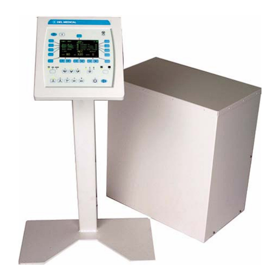
Pre-installation CPI Canada Inc. 1.4.0 GENERATOR LAYOUT AND MAJOR COMPONENTS The dimensions and weight of the generator are shown in the table below. ITEM LENGTH WIDTH HEIGHT WEIGHT Main cabinet in shipping pack 30.5 (775) 21.5 (546) 38 (965) 129 (59) Main cabinet unpacked 22.8 (580) 13.7 (348) - Page 27 CPI Canada Inc. Pre-installation 1.4.0 GENERATOR LAYOUT AND MAJOR COMPONENTS (Cont) H.V. AUXILIARY BOARD GENERATOR CONTROL BOARD AEC BOARD TOUCHSCREEN TRANSFORMER BATTERY (OPTIONAL) FILAMENT BOARD “ LOAD DEFAULTS ” POSITION “ NORMAL ” POSITION CMP200_007A.CDR Figure 1-4: Major generator subassemblies view 2 Use and disclosure is subject to the restrictions on the title page of this CPI document.
-
Page 28: Compatibility Listing
Pre-installation CPI Canada Inc. 1.4.0 GENERATOR LAYOUT AND MAJOR COMPONENTS (Cont) Figure 1-5: Console internal view including EPROM location 1.5.0 COMPATIBILITY LISTING This X-ray generator is compatible with the following equipment: X-RAY TUBES: Refer to the compatibility statement at the end of this chapter. Ω... -
Page 29: Customer Support
CPI Canada Inc. Pre-installation 1.6.0 CUSTOMER SUPPORT Address any questions regarding X-ray generator operation to: Mail: Customer Support Department Communications and Power Industries Canada Inc. 45 River Drive Georgetown, Ontario, Canada L7G 2J4 Telephone: (905) 877-0161 Fax: (905) 877-8320 Attention: Customer Support Department E-mail: marketing@cmp.cpii.com Attention: Customer Support Department... - Page 30 Pre-installation CPI Canada Inc. (This page intentionally left blank) Use and disclosure is subject to the restrictions on the title page of this CPI document. Page 1-26 CMP 200 X-Ray Generator Service Manual Ch # 740987-01 Rev. Y...
-
Page 31: Cmp 200 X-Ray Generator Service Manual Ch # 740987-01 Rev. Y Page
CPI Canada Inc. Pre-installation REPLACE THIS PAGE WITH “COMPATIBILITY STATEMENT” form Use and disclosure is subject to the restrictions on the title page of this CPI document. CMP 200 X-Ray Generator Service Manual Ch # 740987-01 Rev. Y Page 1-27... - Page 32 Pre-installation CPI Canada Inc. (This page intentionally left blank) Use and disclosure is subject to the restrictions on the title page of this CPI document. Page 1-28 CMP 200 X-Ray Generator Service Manual Ch # 740987-01 Rev. Y...
- Page 33 CPI Canada Inc. Installation Chapter 2 INSTALLATION CONTENTS: 2.1.0 INTRODUCTION ............................2 2.2.0 UNPACKING ............................... 2 2.3.0 REMOVING THE GENERATOR COVER ....................3 2.4.0 MAJOR COMPONENT LAYOUT ........................ 3 2.5.0 EQUIPMENT PLACEMENT ........................3 2.5.1 Main Cabinet ............................3 2.5.2 Control Console ............................
-
Page 34: Introduction
Installation CPI Canada Inc. 2.1.0 INTRODUCTION This chapter contains instructions for unpacking, positioning, and cabling the CMP 200 X-ray generator, allowing for initial power-up and tube auto calibration. 2.2.0 UNPACKING Inspect the pack for evidence of shipping damage. If there is evidence of shipping damage, note this in the event that a damage claim is justified. -
Page 35: Removing The Generator Cover
CPI Canada Inc. Installation 2.3.0 REMOVING THE GENERATOR COVER Remove and set aside the screws and washers securing the cover to the generator chassis. Carefully lift the cover off the chassis. 2.4.0 MAJOR COMPONENT LAYOUT Refer to GENERATOR LAYOUT AND MAJOR COMPONENTS in chapter 1 for major component identification and layout. -
Page 36: Anchoring The Generator To The Floor
Installation CPI Canada Inc. 2.5.2 Control Console (Cont) NOTE: DO NOT LOCATE THE CONTROL CONSOLE WHERE X-RADIATION MAY BE PRESENT DURING INSTALLATION OR OPERATION. YOU MAY CHOOSE TO TEMPORARILY LOCATE THE CONSOLE NEAR THE GENERATOR FOR INITIAL PROGRAMMING AND CALIBRATION. IF THIS IS SO, PLEASE COMPLETE THE FINAL CONSOLE INSTALLATION PER THIS SECTION WHEN THE GENERATOR INSTALLATION IS COMPLETED. - Page 37 CPI Canada Inc. Installation 2.6.1 Control Console (Cont) Figure 2-1: Console cable connector damage example Connect the free end of the console cable as follows. For the membrane console, connect the free end of the console cable to J8 at the rear of the console.
- Page 38 Installation CPI Canada Inc. 2.6.1 Control Console (Cont) Figure 2-2: Console cable routing Figure 2-3 shows the designations of the connectors on the rear panel of the control console. DO NOT CONNECT UNAPPROVED EQUIPMENT TO THE REAR OF THE CONSOLE. For the membrane console, J3 is for connection of an external hand switch, J4 is a serial port for use by an external computer, and J8 is for the interconnect cable to the generator main cabinet.
-
Page 39: Hand Switch (Optional)
CPI Canada Inc. Installation MEMBRANE CONSOLE CONSOLE GENERATOR GROUND DATA HAND INTERFACE CONTRAST LINK SWITCH TOUCH SCREEN CONSOLE DATA CONSOLE LINK GROUND GENERATOR INTERFACE HAND SWITCH MEMBRANE SWITCH ASSEMBLY (ON / OFF AND PREP / X-RAY SWITCHES) CMP RAD_CONS.CDR Figure 2-3: Rear of control console 2.6.2 Hand Switch (Optional) The optional hand switch, if ordered from CPI Canada Inc, is supplied pre-wired to a male 9 pin... -
Page 40: Stator Connections
Installation CPI Canada Inc. 2.6.3 Stator Connections Refer to figure 2-4 for the X-ray tube stator and thermal switch connections. Route the X-ray tube stator cable to the stator terminal block J7 on the H.V. auxiliary board. This is shown in figure 2-4. USE OF A SHIELDED STATOR CABLE IS RECOMMENDED. -
Page 41: Power Line Mains
CPI Canada Inc. Installation 2.6.5 Power Line Mains WARNING: TO AVOID ELECTRICAL SHOCK, ENSURE THAT THE AC MAINS DISCONNECT IS LOCKED IN THE OFF POSITION, AND THAT ALL MAINS CABLES ARE DE- ENERGIZED BEFORE CONNECTING TO THE GENERATOR. Refer to chapter 1 for generator power and generator power line requirements. Temporarily remove the fan and fan-mounting bracket by removing the three screws that secure this assembly to the chassis divider panel. - Page 42 Installation CPI Canada Inc. 2.6.5 Power Line Mains (Cont) Figure 2-5: Generator mains connection Use and disclosure is subject to the restrictions on the title page of this CPI document. Page 2-10 CMP 200 X-Ray Generator Service Manual Ch # 740987-02 Rev.
-
Page 43: High Tension Cables
CPI Canada Inc. Installation 2.6.6 High Tension Cables The X-ray tube should be mounted in its normal fixture i.e. tube stand or other device. Verify that the HT cable terminations are clean, in good condition, and coated with vapor proof compound. -
Page 44: Room Equipment
Installation CPI Canada Inc. 2.6.8 Room Equipment Refer to chapter 3C for connection of Buckys, interlocks, room lights, DAP, and collimator lamp and system locks power, and to chapter 3D for installation and calibration of AEC. It is suggested that these items not be connected until after the initial run-up of the generator is complete, and the tube auto calibration routine has been performed as described near the end of this chapter. -
Page 45: Low Speed Starter Tube Select Table
CPI Canada Inc. Installation 2.7.2 Low Speed Starter Tube Select Table TABLE 2-1: SUPPORTED TUBE TYPES TUBE TYPE TUBE TYPE BOOST SHIFT CAPAC H.V. AUXILIARY VOLTAGE (HOUSING) (INSERT) BOARD PART NO. 33 μF Comet DO7 240 VAC 739442-00 25/50 Ω stator 739445-00 33 μF Comet DO9... - Page 46 Installation CPI Canada Inc. 2.7.2 Low Speed Starter Tube Select Table (Cont) TUBE TYPE TUBE TYPE BOOST SHIFT CAPAC H.V. AUXILIARY VOLTAGE (HOUSING) (INSERT) BOARD PART NO. 33 μF Varian A192 240 VAC 739442-00 B130 A272 739445-00 B150 A282 Std “R” stator A286 A292 G256...
-
Page 47: Initial Run-Up
CPI Canada Inc. Installation 2.8.0 INITIAL RUN-UP This section describes the procedure for auxiliary transformer and touchscreen transformer (if fitted) line voltage tap selection and for initial power-on of the generator after it has first been installed. PLEASE OBSERVE THE FOLLOWING POINTS REGARDING THE MAIN DISTRIBUTION TRANSFORMER: •... - Page 48 Installation CPI Canada Inc. 2.8.1 Auxiliary Transformer Line Voltage Tap Selection (Cont) Figure 2-7: Auxiliary transformer, terminal view For 400 / 480 VAC generators: The 400 / 480 V tap setting only needs to be changed if a 400 V generator is to be operated from 480 V mains, or if a 480 V generator is to be operated from 400 V.
-
Page 49: Touchscreen Transformer Line Voltage Tap Selection
CPI Canada Inc. Installation 2.8.2 Touchscreen Transformer Line Voltage Tap Selection This applies to 400 / 480 V generators with the optional touchscreen transformer only: The touchscreen transformer line voltage tap is factory set to match the line voltage that was specified at the time of the order. -
Page 50: Initial Voltage Measurements
Installation CPI Canada Inc. 2.8.3 Initial Voltage Measurements If the mains supply is compatible with the generator, switch on the main breaker and / or the disconnect switch and check for the following voltages: NOTE: DO NOT SWITCH THE GENERATOR ON AT THIS TIME (ONLY THE AC MAINS TO THE GENERATOR IS TO BE SWITCHED ON). -
Page 51: Tube Ma Auto Calibration
CPI Canada Inc. Installation 2.9.0 TUBE MA AUTO CALIBRATION It is recommended that the generator be tested at this point with only the rotor and high tension cables connected. The generator should be able to complete an X-ray tube calibration and seasoning cycle without other equipment connected to the generator (other than the basic interlocks as noted below). - Page 52 Installation CPI Canada Inc. (This page intentionally left blank) Use and disclosure is subject to the restrictions on the title page of this CPI document. Page 2-20 CMP 200 X-Ray Generator Service Manual Ch # 740987-02 Rev. Y...
- Page 53 CPI Canada Inc. Interfacing, Programming, & Calibration CHAPTER 3 INTERFACING, PROGRAMMING, AND CALIBRATION 3.0.0 INTRODUCTION 3.1.0 Purpose This chapter describes the interfacing of the CMP 200 X-ray generator to Bucky’s, interlocks, collimator lamp, etc, and to the AEC chambers (if the AEC option is fitted). Generator programming and AEC calibration is also covered in this chapter.
- Page 54 Interfacing, Programming, & Calibration CPI Canada Inc. (This page intentionally left blank.) Use and disclosure is subject to the restrictions on the title page of this CPI document. Page 3-2 CMP 200 X-Ray Generator Service Manual Ch # 740987-03 Rev. B...
- Page 55 CPI Canada Inc. Interfacing and Programming CHAPTER 3C INTERFACING AND PROGRAMMING CONTENTS: 3C.1.0 INTRODUCTION ............................. 3C-3 3C.2.0 WIRING TO INPUTS & OUTPUTS ......................... 3C-3 3C.2.1 Inputs ................................3C-3 3C.2.2 Outputs ................................ 3C-4 3C.2.3 Inputs & Outputs (simplified schematic) ...................... 3C-6 3C.2.4 AEC Interconnect............................
- Page 56 Interfacing and Programming CPI Canada Inc. 3C.13.0 TOUCHSCREEN SYSTEM UTILITIES ....................... 3C-64 3C.13.1 Accessing the Utilities Menu ........................3C-64 3C.13.2 APR Editor ............................... 3C-66 3C.13.3 APR Backup / Restore ..........................3C-71 3C.13.4 Date / Time Setup ............................ 3C-73 3C.13.5 Receptor Symbols............................ 3C-75 3C.13.6 TouchScreen Setup ..........................
-
Page 57: 1.0 Introduction
CPI Canada Inc. Interfacing and Programming 3C.1.0 INTRODUCTION This chapter describes the interfacing of the CMP 200 X-ray generator to Bucky(s), interlocks, room lights, DAP, and collimator lamp and tube stand locks, and also describes the generator programming. 3C.2.0 WIRING TO INPUTS & OUTPUTS NOTE: THE INSTALLER MUST PROVIDE THE NECESSARY INTERFACING CABLES FOR WIRING TO THE GENERATOR INPUTS AND OUTPUTS DESCRIBED IN THIS SECTION. -
Page 58: 2.2 Outputs
Interfacing and Programming CPI Canada Inc. 3C.2.1 Inputs (Cont) H.V. AUXILIARY BOARD DEFINITION J2-5 (-) Bucky 1 ready. A contact closure from pin 5 to 6 indicates J2-6 (+) BUCKY 1 READY. J4-5 (-) Bucky 2 ready. A contact closure from pin 5 to 6 indicates J4-6 (+) BUCKY 2 READY. - Page 59 CPI Canada Inc. Interfacing and Programming 3C.2.2 Outputs (Cont) IN SOME INSTALLATIONS, BUCKY START RELAYS K1 OR K3 ON THE H.V. AUXILIARY BOARD MAY DRIVE THE INPUTS OF OPTO COUPLERS OR OTHER LOW CURRENT DEVICES ON THE BUCKY. THE LEAKAGE CURRENT THROUGH THE R-C SNUBBER THAT IS CONNECTED ACROSS THE RELAY CONTACTS (C3 AND R2 FOR K1, C10 AND R15 FOR K3) MAY BE SUFFICIENT TO ENERGIZE THE BUCKY INPUTS WHEN THE RELAYS ARE OPEN.
-
Page 60: 2.3 Inputs & Outputs (Simplified Schematic)
Interfacing and Programming CPI Canada Inc. 3C.2.3 Inputs & Outputs (simplified schematic) ** 24 VDC BUCKY RETURN 110 / 220 VAC BUCKY 1 OUTPUTS +12 VDC BUCKY 1 START BUCKY 1 START +24 VDC COMMAND BUCKY 1 READY * BUCKY 1 READY +24 VDC INTERLOCK 1 +24 VDC... -
Page 61: 2.4 Aec Interconnect
CPI Canada Inc. Interfacing and Programming 3C.2.4 AEC Interconnect Refer to chapter 3D for an overview of AEC theory, for AEC chamber connections, and for the AEC calibration procedure. 3C.3.0 GENERATOR PROGRAMMING If you are using a membrane console, the generator may be programmed and calibrated via the control console or via GenWare®. -
Page 62: 4.0 Generator Setup Menu
Interfacing and Programming CPI Canada Inc. 3C.3.1 Entering Into Programming Mode (Cont) Use these steps to access the GENERATOR SETUP menu (membrane console). Step Action (membrane console) Action (GenWare®) Start with the generator switched OFF. While pressing and holding the MENU button, press the power ON button on the console. -
Page 63: 5.0 Utility Menu
CPI Canada Inc. Interfacing and Programming 3C.4.0 GENERATOR SETUP MENU (Cont) MENU SUBMENUS EQUIVALENT FUNCTION (MEMBRANE (MEMBRANE CONSOLE) (GenWare®) CONSOLE) • • TUBE SELECTION Tube Selection utility. CONFIGURATION • • GENERATOR LIMITS Generator Limits utility. • • RECEPTOR SETUP Receptor Setup utility. •... -
Page 64: 5.1 Setting Time And Date
Interfacing and Programming CPI Canada Inc. 3C.5.1 Setting Time And Date This procedure allows the time and date to be set, or to be changed. The SET TIME & DATE menu for the membrane console is shown below. * SET TIME & DATE * YEAR: 2002 HOUR: 18... - Page 65 CPI Canada Inc. Interfacing and Programming 3C.5.1 Setting Time And Date (Cont) Use these steps to set the time and date. Step Action (membrane console) Action (GenWare®) From the GENERATOR SETUP menu, From the GenWare® GENERATOR select the UTILITY menu. UTILITIES application, select Date and Time from the Utility menu, or use the date and time button...
-
Page 66: 5.2 Error Log
Interfacing and Programming CPI Canada Inc. 3C.5.2 Error Log This utility allows display of the error messages stored in the generator’s error log. The ERROR LOG menu for the membrane console is shown below. * ERROR LOG * ERROR # 1 OF 18 DATE: 8-19-2002 TIME: 13:09... -
Page 67: 5.3 Statistics
CPI Canada Inc. Interfacing and Programming 3C.5.2 Error Log (Cont) Use these steps to review the error log. Step Action (membrane console) Action (GenWare®) From the UTILITY menu, select ERROR Select Error Log from the Utility menu, or LOG. use the error log button on the GenWare®... - Page 68 Interfacing and Programming CPI Canada Inc. 3C.5.3 Statistics (Cont) ® Figure 3C-5: GenWare Statistics utility Use these steps to view the generator statistics. Step Action (membrane console) Action (GenWare®) From the UTILITY menu, select Select Generator Statistics from the Utility STATISTICS.
-
Page 69: 5.4 Console
CPI Canada Inc. Interfacing and Programming 3C.5.4 Console The CONSOLE CONFIG menus allow setting of specific console operating features to suit operator preferences, and also allow resetting of the console parameters to the factory defaults. CONSOLE CONFIG screen 1 * CONSOLE CONFIG* SLOW KEY REPEAT: 200MS LCD SCREEN... - Page 70 Interfacing and Programming CPI Canada Inc. 3C.5.4 Console (Cont) FUNCTION DESCRIPTION (MEMBRANE CONSOLE) NO allows the operator to select an APR view, and still have the ability to APR MODE manually select receptors, focus, technique, film screen, AEC fields, etc. YES allows the operator to select all of the above EXCEPT the technique selection (AEC, mAs, mA/ms) i.e.
-
Page 71: 6.0 Apr Editor
CPI Canada Inc. Interfacing and Programming 3C.5.4 Console (Cont) Step Action (membrane console) Press >>. Do not perform this step unless you intend to restore the console factory defaults. To restore the console factory default settings, select LOAD CONSOLE DEFAULTS? and then toggle the adjacent selection button to select YES. - Page 72 Interfacing and Programming CPI Canada Inc. 3C.6.0 APR EDITOR (Cont) Definition of the APR EDITOR function. FUNCTION DESCRIPTION (MEMBRANE CONSOLE) APR EDITOR Enables / disables the ability of the operator to make and then save changes to APR techniques.. Allows the operator to change the default APR technique(s), ENABLED: and then save the changes to memory.
-
Page 73: 7.0 Generator Configuration
CPI Canada Inc. Interfacing and Programming 3C.7.0 GENERATOR CONFIGURATION The GEN CONFIGURATION menu presents the user with the selections shown below. These are described in detail in this section. * GEN CONFIGURATION * TUBE SELECTION AEC SETUP GENERATOR LIMITS AEC CALIBRATION RECEPTOR SETUP TUBE CALIBRATION I/O CONFIGURATION... - Page 74 Interfacing and Programming CPI Canada Inc. 3C.7.1 Tube Selection (cont) TUBE SELECTION screen 2 * TUBE 1 SELECTION * RAD14 0.6/1.2 RAD74 0.6/1.5 RAD21 0.6/1.2 RAD92 0.6/1.2 RAD56 0.6/1.2 DX10HS 0.6/1.0 RAD60 0.6/1.2 DX92HS 0.6/1.2 << >> TUBE SELECTION screen 3 * TUBE 1 SELECTION * DX93HS 0.6/1.5 RO1750 0.6/1.3...
- Page 75 CPI Canada Inc. Interfacing and Programming 3C.7.1 Tube Selection (cont) The next three menus show the default tube limits. These menus appear after a tube has been selected in the previous steps. TUBE DEFAULTS screen 1 *TUBE 1: RAD60 0.6/1.2 12º...
- Page 76 Interfacing and Programming CPI Canada Inc. 3C.7.1 Tube Selection (cont) ® Figure 3C-6: GenWare Tube Selection window, Tube Library tab ® Figure 3C-7: GenWare Tube Selection window, Tube Settings tab Use and disclosure is subject to the restrictions on the title page of this CPI document. Page 3C-22 CMP 200 X-Ray Generator Service Manual Ch # 740987-04...
- Page 77 CPI Canada Inc. Interfacing and Programming 3C.7.1 Tube Selection (cont) ® Figure 3C-8: GenWare Tube Selection window, kW Ratings at 100ms tab ® Figure 3C-9: GenWare Tube Selection window, Filament Parameters tab Use and disclosure is subject to the restrictions on the title page of this CPI document. CMP 200 X-Ray Generator Service Manual Ch # 740987-04 Rev.
- Page 78 Interfacing and Programming CPI Canada Inc. 3C.7.1 Tube Selection (cont) ® Figure 3C-10: GenWare Tube Selection window, Anode Heating tab Definitions of TUBE SELECTION menu items. FUNCTION FUNCTION DESCRIPTION (MEMBRANE (GenWare®) CONSOLE) This selection is permanently set to low speed. TUBE SPEED Tube Speed Sets the maximum small focus low speed kW limit (@ 100...
- Page 79 CPI Canada Inc. Interfacing and Programming 3C.5.1 Tube Selection (Cont) FUNCTION FUNCTION DESCRIPTION (MEMBRANE (GenWare®) CONSOLE) FIL BOOST Filament Boost Sets the filament rapid boost duration in order to quickly raise the filament temperature. Time (ms) FIL PREHEAT Filament Preheat The time that the filament is held at the required emission level before an exposure is permitted.
- Page 80 Interfacing and Programming CPI Canada Inc. 3C.5.1 Tube Selection (Cont) When the desired tube is selected, the default limits are displayed (membrane console). Please consult the X- ray tube data sheet(s) before making any changes. The low speed starter operates at 50 Hz for 50 Hz mains, or 60 Hz for 60 Hz mains. Therefore, the 60 Hz tube ratings are automatically derated for 50 Hz operation, if required.
- Page 81 CPI Canada Inc. Interfacing and Programming 3C.5.1 Tube Selection (Cont) Step Action (membrane console) Action (GenWare®) Select FIL BOOST. Use the + or – buttons Set the filament rapid boost duration via the to set the filament rapid boost duration. Filament Boost Time (ms) dialog box.
-
Page 82: 7.2 Generator Limits
Interfacing and Programming CPI Canada Inc. 3C.5.1 Tube Selection (Cont) TUBE SELECTION TUBE 1 DEFAULT SELECTED TUBE SELECTED TUBE SPEED MAX SF KW LS MAX LF KW LS MAX KV SF STANDBY LF STANDBY SF MAX LF MAX FIL BOOST FIL PREHEAT MAX SF MA ANODE HU WARNING... - Page 83 CPI Canada Inc. Interfacing and Programming 3C.7.2 Generator Limits (Cont) ® Figure 3E-11: GenWare Generator Limits window Definitions of GENERATOR LIMITS menu items. FUNCTION FUNCTION DESCRIPTION (MEMBRANE (GenWare®) CONSOLE) Sets the maximum generator kW limit. MAX KW Max. Generator Power (kW) Sets the maximum generator mA limit.
- Page 84 Interfacing and Programming CPI Canada Inc. 3C.7.2 Generator Limits (Cont) Use these steps to set the generator limits. Refer to the definitions in the previous table. Step Action (membrane console) Action (GenWare®) From the GEN CONFIGURATION menu, Select Generator Limits from the Setup menu, or use the generator limits button select GENERATOR LIMITS.
-
Page 85: 7.3 Receptor Setup
CPI Canada Inc. Interfacing and Programming 3C.7.3 Receptor Setup The RECEPTOR SETUP function allows each of the image receptors to be programmed as defined in the table following the example menu screens. The RECEPTOR SETUP menus for the membrane console are shown below. MENU 1 * RECEPTOR SETUP [sym] * TUBE:... - Page 86 Interfacing and Programming CPI Canada Inc. 3C.7.3 Receptor Setup (Cont) MENU 3 * RECEPTOR SETUP [sym] DEFAULTS* TECHNIQUE: AEC LEFT FIELD: YES FOCUS: SMALL CENTER FIELD: YES FILM SCREEN: 1 RIGHT FIELD: YES << >> MENU 4 * RECEPTOR SETUP [sym] DEFAULTS* DENSITY: <<...
- Page 87 CPI Canada Inc. Interfacing and Programming 3C.7.3 Receptor Setup (Cont) ® Figure 3C-12: GenWare Receptor Setup window, Receptor Properties tab ® Figure 3C-13: GenWare Receptor Setup window, AEC tab Use and disclosure is subject to the restrictions on the title page of this CPI document. CMP 200 X-Ray Generator Service Manual Ch # 740987-04 Rev.
- Page 88 Interfacing and Programming CPI Canada Inc. 3C.7.3 Receptor Setup (Cont) ® Figure 3C-14: GenWare Receptor Setup window, Receptor Defaults tab Definitions of RECEPTOR SETUP menu items. FUNCTION FUNCTION DESCRIPTION (MEMBRANE (GenWare®) CONSOLE) This function allows the receptor to be disabled. TUBE Receptor Enable checkbox...
- Page 89 CPI Canada Inc. Interfacing and Programming 3C.5.3 Receptor Setup (Cont) FUNCTION FUNCTION DESCRIPTION (MEMBRANE (GenWare®) CONSOLE) MEMORY Memory Defines the techniques that will be defaulted to when a receptor is selected. The selected receptor will remember it’s YES / on: last techniques such...
- Page 90 Interfacing and Programming CPI Canada Inc. 3C.5.3 Receptor Setup (Cont) FUNCTION FUNCTION DESCRIPTION (MEMBRANE (GenWare®) CONSOLE) AEC BACKUP AEC Mode Defines the AEC backup mode to be used: FIXED: generator will determine maximum AEC backup time, not to exceed preset AEC backup mAs/ms values or system limits.
- Page 91 CPI Canada Inc. Interfacing and Programming 3C.5.3 Receptor Setup (Cont) FUNCTION FUNCTION DESCRIPTION (MEMBRANE (GenWare®) CONSOLE) THE FOLLOWING SELECTIONS ARE ONLY AVAILABLE IF DEFAULTS WAS ENABLED AS PREVIOUSLY DESCRIBED. TECHNIQUE Technique Defines which technique will be defaulted to when a receptor is selected.
- Page 92 Interfacing and Programming CPI Canada Inc. 3C.5.3 Receptor Setup (Cont) If the image receptor defaults are changed, please record the original defaults in a copy of the following table: IMAGE RECEPTOR DEFAULT SETTINGS FUNCTION RECEPTO RECEPTO RECEPTO RECEPTO RECEPTO RECEPTO TECHNIQUE FOCUS FILM...
- Page 93 CPI Canada Inc. Interfacing and Programming 3C.5.3 Receptor Setup (Cont) *RECEPTOR SETUP DEFAULTS NOTE: DO NOT SWITCH OFF THE GENERATOR WHILE IN MENUS 3 AND 4. DOING SO WILL CAUSE THE UPDATED RECEPTOR SETUP PARAMETERS NOT TO BE SAVED. IT IS RECOMMENDED THAT THE FIRST RECEPTOR PROGRAMMING BE COMPLETED, THE RECEPTOR SETUP MENUS BE EXITED TO THE GEN CONFIGURATION MENU, THEN THE RECEPTOR SETUP MENU BE RESELECTED TO PROGRAM THE NEXT RECEPTOR.
- Page 94 Interfacing and Programming CPI Canada Inc. 3C.5.3 Receptor Setup (Cont) Step Action (membrane console) Action (GenWare®) Select DEFAULTS. Select the Receptor Defaults tab. Select TECHNIQUE. Toggle the button to Under Technique, select ms, mAs, or AEC. select MA, MAS, or AEC. Select FOCUS.
-
Page 95: 7.4 I/O Configuration
CPI Canada Inc. Interfacing and Programming 3C.7.4 I/O Configuration The I/O CONFIGURATION function allows programming the states of the exposure for the inputs and the outputs on the room interface board. The I/O CONFIGURATION menus for the membrane console are shown below. * INPUTS [sym] * TUBE THERMAL SW. - Page 96 Interfacing and Programming CPI Canada Inc. 3C.7.4 I/O Configuration (cont) ® Figure 3C-15: GenWare Receptor Setup window, Inputs tab ® Figure 3C-16: GenWare Receptor Setup window, Outputs tab Use and disclosure is subject to the restrictions on the title page of this CPI document. Page 3C-42 CMP 200 X-Ray Generator Service Manual Ch # 740987-04...
- Page 97 CPI Canada Inc. Interfacing and Programming 3C.7.4 I/O Configuration (cont) Definitions of I/O CONFIGURATION menu items. FUNCTION FUNCTION DESCRIPTION (MEMBRANE (GenWare®) CONSOLE) TUBE THERMAL Tube Thermal Programs the thermal switch input at J7-1 and J7-2 on the H.V. auxiliary board. Switch Programs the door interlock input at J4-9 and J4-10 on the DOOR ITLK...
- Page 98 Interfacing and Programming CPI Canada Inc. 3C.5.4 I/O Configuration (Cont) MEMBRANE CONSOLE The STATE button on the upper right hand side of the menu selects the current state. The word STATE is preceded by the description of the state: for example, STANDBY. The arrow in the lower middle area points to the current level for the selected state.
- Page 99 CPI Canada Inc. Interfacing and Programming 3C.5.4 I/O Configuration (Cont) GenWare® On the Inputs and Outputs tabs, the generator states are shown above the vertical grey / red bars. For inputs, grey indicates states where the input cannot be programmed. Only states that are shown in red can be changed.
- Page 100 Interfacing and Programming CPI Canada Inc. 3C.5.4 I/O Configuration (Cont) Step Action (membrane console) Action (GenWare®) Reselect I/O CONFIGURATION, and then Select the next receptor to be programmed. select the next receptor to be programmed. Use the Receptor tabs on the Receptor Setup window.
-
Page 101: 7.5 Aec Setup
CPI Canada Inc. Interfacing and Programming 3C.7.5 AEC Setup The AEC SETUP menus allow programming of AEC parameters for each AEC channel. The AEC SETUP menus for the membrane console are shown below. MENU 1 * AEC SETUP* CHANNEL: CHAMBER TYPE: ION LEFT FIELD: FILM SCREEN 1 : YES CENTER FIELD:... - Page 102 Interfacing and Programming CPI Canada Inc. 3C.7.5 AEC Setup (Cont) ® Figure 3C-18: GenWare AEC Setup & Calibration window, AEC Setup tab ® Figure 3C-19: GenWare AEC Setup & Calibration window, Film Screen Options tab Use and disclosure is subject to the restrictions on the title page of this CPI document. Page 3C-48 CMP 200 X-Ray Generator Service Manual Ch # 740987-04...
- Page 103 CPI Canada Inc. Interfacing and Programming 3C.7.5 AEC Setup (Cont) Note the following regarding GenWare® figures 3C-16 and 3C-17: • The AEC Channel display near the top left side of the AEC Setup & Calibration window shows the selected AEC channel. •...
- Page 104 Interfacing and Programming CPI Canada Inc. 3D.4.0 INITIAL AEC SETUP (Cont) FUNCTION FUNCTION DESCRIPTION (MEMBRANE (GenWare®) CONSOLE) Allows left, center, and right field balance. This applies to R FIELD COMP R. Field Comp solid-state AEC chambers only. The calibration procedure C FIELD COMP C.
-
Page 105: 7.6 Aec Calibration
CPI Canada Inc. Interfacing and Programming 3D.4.0 INITIAL AEC SETUP (Cont) Step Action (membrane console) Action (GenWare®) Repeat the above for C FIELD COMP and L Repeat the above for C. Field Comp and L. FIELD COMP Field Comp. Repeat the applicable steps in this section Repeat the applicable steps in this section for the remaining AEC channels. - Page 106 Interfacing and Programming CPI Canada Inc. 3C.7.7 Tube Calibration (Cont) Step Action (membrane console) Action (GenWare®) When finished calibrating the small focus, Repeat the calibration on the large focal press RETURN and then repeat calibration spot. on the large focal spot. When auto-calibration is completed, press EXIT to return to the GENERATOR SETUP menu.
-
Page 107: 8.0 Dap Printer Setup
CPI Canada Inc. Interfacing and Programming 3C.8.0 DAP PRINTER SETUP Connect the DAP printer to the DATA LINK connector J4 on the rear of the console. Refer to the figure “Rear of control console” in chapter 2 of the CMP 200 service manual for the connector location. Follow the procedure in 3C.10.2 to set up and test the DAP printer. -
Page 108: 9.2 Dap Installation
Interfacing and Programming CPI Canada Inc. 3C.9.2 DAP Installation Switch OFF the AC line voltage to the generator at the main disconnect switch. Allow sufficient time for all capacitors in the generator to discharge. Install the DAP chamber as per the manufacturers instructions. The interconnect cable to the generator must be as per 3C.9.1. -
Page 109: 10.2 Dap Setup Menu Items
CPI Canada Inc. Interfacing and Programming 3C.10.1 DAP SETUP Menu (Cont) ® Figure 3C-20: GenWare DAP Setup and display windows 3C.10.2 DAP SETUP Menu Items Definitions of DAP SETUP menu items. FUNCTION FUNCTION DESCRIPTION (MEMBRANE (GenWare®) CONSOLE) Enables or disables the DAP device. DAP checkbox Membrane console: The DAP function is enabled. - Page 110 Interfacing and Programming CPI Canada Inc. 3C.10.2 DAP SETUP Menu Items (Cont) FUNCTION FUNCTION DESCRIPTION (MEMBRANE (GenWare®) CONSOLE) A numeric value, supplied by the DAP device TEST VALUE 1 Test Value 1 manufacturer, that represents the number of pulses generated by the DAP device during TEST mode. Typical terms used by DAP device manufacturers for this function are “Test Pulses”, “Test Value”, or “Test Count”, but other names may be used.
-
Page 111: 11.0 Dap Calibration
CPI Canada Inc. Interfacing and Programming 3C.10.2 DAP SETUP Menu Items (Cont) Use these steps to set up the DAP device. DAP calibration is done after DAP setup Step Action (membrane console) Action (GenWare®) From the GEN CONFIGURATION menu, From the GenWare® GENERATOR select DAP SETUP. -
Page 112: 3C11.1 Equipment Required
Interfacing and Programming CPI Canada Inc. 3C11.1 Equipment Required The following equipment is required for DAP calibration. • An X-ray cassette and film. The speed of the film / screen is not relevant, as the film is only used to determine the area that is irradiated at the dose-measurement plane. -
Page 113: 11.3 Dap Calibration Procedure
CPI Canada Inc. Interfacing and Programming 3C.11.3 DAP Calibration Procedure TUBE 1 DAP chamber 1 70 cm Dosimeter plane and film plane 20 cm DAP chamber 2 TUBE 2 TYPICAL SETUP FOR DAP CALIBRATION FILE: DAP.CDR Figure 3C-21: DAP setup Use these steps to calibrate the DAP meter(s) in the generator. - Page 114 Interfacing and Programming CPI Canada Inc. 3C.11.3 DAP Calibration Procedure (Cont) Step Action Replace the dosimeter with an X-ray cassette and film if available. The film plane must be at the same location as the dosimeter was in step 8. If using an image sensor such as an I.I., or flat panel, or other non-film image sensor, the image pickup plane must be at the same location as the dosimeter was in step 8.
-
Page 115: 11.4 Dap Calculation Worksheet
CPI Canada Inc. Interfacing and Programming 3C.11.3 DAP Calibration Procedure (Cont) X-RAY CASSETTE 13.2 EXPOSED 13.6 AREA ILLUMINATED DEVELOPED FILM COLLIMATOR FIELD Figure 3C-22: Irradiated area vs. available image area 3C.11.4 DAP Calculation Worksheet STEP ACTION RESULT Measured dose: _____________ mR Convert mR to mGy if necessary by multiplying mR X 0.00873. - Page 116 Interfacing and Programming CPI Canada Inc. 3C.11.4 DAP Calculation Worksheet (Cont) Measure and record the exposed area of the film (Length _____________ Length (cm) X Width). _____________ Width (cm) Calculate the exposed area in cm (length X width). _____________ Area (cm Multiply the dose in mGy (step 1) X the area in cm (step 2).
-
Page 117: 12.0 Data Link
CPI Canada Inc. Interfacing and Programming 3C.11.4 DAP Calculation Worksheet (Cont) Sample percentage error calculation (step 5): (36.44 - 40) -3.56 X 100 = X 100 = -8.9 % 3C.12.0 DATA LINK Used with the CPI GenWare® utility software. This allows for data communication with a computer in order to ™... -
Page 118: 13.0 Touchscreen System Utilities
Interfacing and Programming CPI Canada Inc. 3C.13.0 TOUCHSCREEN SYSTEM UTILITIES This section applies to generators with the touchscreen option only. The system utilities menu allows access to the following functions: FUNCTION DESCRIPTION Allows the APR to be edited. Changes may be saved to memory. APR Editor Allows the APR data to be backed up, and backed-up APR data to be APR Backup / Restore... - Page 119 CPI Canada Inc. Interfacing and Programming 3C.13.1 Accessing the Utilities Menu (Cont) Figure 3C-23: Main menu Figure 3C-24: Password window Use and disclosure is subject to the restrictions on the title page of this CPI document. CMP 200 X-Ray Generator Service Manual Ch # 740987-04 Rev.
-
Page 120: 13.2 Apr Editor
Interfacing and Programming CPI Canada Inc. 3C.13.1 Accessing the Utilities Menu (Cont) Figure 3C-25: System utilities menu 3C.13.2 APR Editor It is strongly suggested that you review the section ANATOMICAL PROGRAMMING SELECTOR in the operator’s manual before proceeding. A good understanding of the terminology and APR menu structures is needed to make APR changes. - Page 121 CPI Canada Inc. Interfacing and Programming 3C.13.2 APR Editor (Cont) Figure 3C-26: APR editor window NOTE: THE DISPLAY ON YOUR SYSTEM MAY VARY DEPENDING ON GENERATOR TYPE, AND ON PROGRAMMING AND TECHNIQUE SELECTIONS. MINOR VARIATIONS MAY EXIST IN COLOR SCHEME AND GRAPHIC STYLES (SKINS) TO SUIT SPECIFIC CUSTOMER REQUIREMENTS.
- Page 122 Interfacing and Programming CPI Canada Inc. 3C.13.2 APR Editor (Cont) To change parameters or techniques for an existing APR item. Step Action Select the APR item to be changed. If the APR item is in a submenu of a menu or procedural item, select the parent menu item or procedural item, then press Open Sub- Menu.
- Page 123 CPI Canada Inc. Interfacing and Programming 3C.13.2 APR Editor (Cont) To delete an APR item. Step Action Select the APR item to be deleted. The selection will be highlighted. Press Delete. A pop-up window will display asking if you are sure you want to delete this item.
- Page 124 Interfacing and Programming CPI Canada Inc. 3C.13.2 APR Editor (Cont) To add, edit, or delete a menu item. Step Action To delete a menu item, follow the steps in “To delete an APR item”. Doing so will also delete the submenu associated with that menu item. To edit a menu item, follow the steps in “To edit (change the name of) an APR item”.
-
Page 125: 13.3 Apr Backup / Restore
CPI Canada Inc. Interfacing and Programming 3C.13.3 APR Backup / Restore Use these steps to access the APR backup / restore function. Step Action From the system utilities menu, press APR Backup / Restore. A pop-up window (figure 3C- 27) will display showing the available backup files and the factory-default APR files in various languages. - Page 126 Interfacing and Programming CPI Canada Inc. 3C.13.3 APR Backup / Restore (Cont) To restore backed-up APR data. Step Action Select the APR data file to be restored. The selection will be highlighted. Press Restore. After a brief delay, a pop-up window will display indicating that restore was successful. Press OK.
-
Page 127: 13.4 Date / Time Setup
CPI Canada Inc. Interfacing and Programming 3C.13.3 APR Backup / Restore (Cont) Step Action Set up the communications port on the touchscreen as described in the section TOUCH SCREEN SETUP, under Settings. To copy an APR file from the touchscreen to the laptop, select the desired file. Then press A file-transfer status window will pop up. - Page 128 Interfacing and Programming CPI Canada Inc. 3C.13.4 Date / Time Setup (Cont) Figure 3C-28: Date and time setup window Use and disclosure is subject to the restrictions on the title page of this CPI document. Page 3C-74 CMP 200 X-Ray Generator Service Manual Ch # 740987-04 Rev.
-
Page 129: 13.5 Receptor Symbols
CPI Canada Inc. Interfacing and Programming 3C.13.5 Receptor Symbols The current image receptor symbols may be replaced with predefined symbols chosen from the receptor symbols library. Each image receptor button will always select a predefined image receptor (i.e. table Bucky, wall Bucky, DR, etc.). -
Page 130: 13.6 Touchscreen Setup
Interfacing and Programming CPI Canada Inc. 3C.13.5 Receptor Symbols (Cont) Figure 3C-29: Receptor symbols window 3C.13.6 TouchScreen Setup The touchscreen setup menu accesses submenus that allow the service engineer to perform the following functions: • Enable or disable certain console functions (voice messaging, audible generator ready indication, auto power off). - Page 131 CPI Canada Inc. Interfacing and Programming 3C.13.6 TouchScreen Setup (Cont) Figure 3C-30: TouchScreen setup window, Settings tab • The System Code is a unique code assigned to each touchscreen on which the software is installed. • The License is a code specifically assigned to each touchscreen. This enables options in the features tab. Please consult the factory to obtain a new license code if it is desired to enable new features, or to reinstall the existing license should the license code be accidentally overwritten.
- Page 132 Interfacing and Programming CPI Canada Inc. 3C.13.6 TouchScreen Setup (Cont) Settings The functions near the left side of the settings window are enabled when checked (√). FUNCTION DESCRIPTION Voice Messaging Enables / disables verbal status and error messages. Error and status messages will be annunciated. Languages On (√): other than English may not be available.
- Page 133 CPI Canada Inc. Interfacing and Programming 3C.13.6 TouchScreen Setup (Cont) Step Action Select the Generator Type. Use CMP 200. The touchscreen will not properly communicate with the generator unless this is set correctly. Set the Screen Saver Interval. This sets the time from the last activity on the touchscreen until the screen saver is activated.
- Page 134 Interfacing and Programming CPI Canada Inc. 3C.13.6 TouchScreen Setup (Cont) Step Action Check the applicable item to enable that function. Press OK to continue or CANCEL to return to the system utilities menu without making any changes. If OK was pressed, a pop-up window will display asking if you wish to save the changes.
-
Page 135: 13.7 Touchscreen Calibration
CPI Canada Inc. Interfacing and Programming 3C.13.6 TouchScreen Setup (Cont) Step Action Press OK to continue; CANCEL cancels the changes. A pop-up window will display asking if you wish to save the changes. Press YES to save the changes. Press NO to return to the system utilities menu; CANCEL cancels the changes. BE SURE TO RECORD THE NEW SERVICE PASSWORD BEFORE CHANGING THE FACTORY-DEFAULT PASSWORD. -
Page 136: 13.8 Data Link
Interfacing and Programming CPI Canada Inc. 3C.13.7 TouchScreen Calibration (Cont) Step Action When the touchscreen console restarts, the touchscreen calibration needs to be verified. A screen indicating Please press the target buttons… will appear. You must press the center of the target at the top left of the screen, plus the center of the next three targets within 30 seconds. - Page 137 CPI Canada Inc. AEC Calibration CHAPTER 3D AEC CALIBRATION CONTENTS: 3D.1.0 INTRODUCTION.............................3D-2 3D.1.1 AEC Limitations: Minimum and Maximum Exposure Times ..............3D-3 3D.1.2 Film/Screen Response vs. kV ........................3D-3 3D.1.3 AEC Calibration Range ..........................3D-4 3D.2.0 PRECALIBRATION SETUP ...........................3D-5 3D.2.1 AEC Setup Worksheet ..........................3D-5 3D.2.2 AEC Precalibration Checks.........................3D-7 3D.2.3 AEC Chamber Installation ...........................3D-7 3D.2.4 AEC Board (Solid State Chambers)......................3D-9...
-
Page 138: 1.0 Introduction
AEC Calibration CPI Canada Inc. 3D.1.0 INTRODUCTION This section describes the interfacing and calibration of the various AEC board assemblies that are used in CMP 200 X-ray generators. THE GENERATOR IS FACTORY CONFIGURED FOR SPECIFIC AEC CHAMBERS. REFER TO THE COMPATIBILITY STATEMENT CHAPTER... - Page 139 CPI Canada Inc. AEC Calibration 3D.1.1 AEC Limitations: Minimum and Maximum Exposure Times AEC exposures should normally be kept well under one second. When X-ray techniques are used that result in longer exposures, the film density will not be correct due to failure of reciprocity of the film. Care must be exercised when using low kV values with table Buckys because most table tops and grids absorb considerable radiation in the range of 60 –...
-
Page 140: 1.3 Aec Calibration Range
AEC Calibration CPI Canada Inc. 3D.1.3 AEC Calibration Range Since the CMP 200 family of X-ray generators allows for up to three separate film screen combinations to be calibrated, the following points must be considered: • The AEC board allows for a zero to a maximum of 10-volt ramp at the comparator input. All AEC signals must fit within this range (for all film / screens, densities, and techniques). -
Page 141: 2.0 Precalibration Setup
CPI Canada Inc. AEC Calibration 3D.2.0 PRECALIBRATION SETUP 3D.2.1 AEC Setup Worksheet Before continuing, it is suggested that a copy of the table below be filled in with all required information. Refer to the example AEC setup worksheet on the next page. FUNCTION RECEPTOR 1 RECEPTOR 2... - Page 142 AEC Calibration CPI Canada Inc. 3D.2.1 AEC Setup Worksheet (Cont) Note: The example below is supplied for reference only. It does not represent an actual installation. FUNCTION RECEPTOR 1 RECEPTOR 2 RECEPTOR 3 Film/Screen Lanex/reg Lanex/reg Lanex/reg Lanex/med Lanex/chest Nominal optical density: Grid ratio/SID: 12:1 10:1...
-
Page 143: 2.2 Aec Precalibration Checks
CPI Canada Inc. AEC Calibration 3D.2.2 AEC Precalibration Checks It is recommended that a copy of the form below be filled in with the required information before attempting AEC calibration. Verify that the AEC chambers are mounted correctly CHECK: in the Bucky. Note that some chamber types must be physically isolated from equipment ground, refer to figure 3D-3 as an example. - Page 144 AEC Calibration CPI Canada Inc. 3D.2.3 AEC Chamber Installation (Cont) Figure 3D-3: AEC chamber installation Use and disclosure is subject to the restrictions on the title page of this CPI document. Page 3D-8 Rev. C CMP 200 Service Manual Ch # 740987-11...
-
Page 145: 2.4 Aec Board (Solid State Chambers)
CPI Canada Inc. AEC Calibration 3D.2.4 AEC Board (Solid State Chambers) The AEC board shown below is compatible with various makes / models of solid-state chambers (i.e. Comet, Ziehm, Gilardoni). This AEC board is used in various models of generators requiring those AEC chamber types. - Page 146 AEC Calibration CPI Canada Inc. 3D.2.4 AEC Board (Solid State Chambers) Cont Tables 3D-4 and 3D-5 show the pin outs for both the 6 pin circular connectors and for the 5 pin in-line connectors on the AEC board in figure 3D-4. FUNCTION Anode NOTE: PINS 1, 2, AND 3 ON THE...
-
Page 147: 2.5 Aec Board (Solid State Chambers)
CPI Canada Inc. AEC Calibration 3D.2.5 AEC Board (Solid State Chambers) The AEC board shown below is compatible with various makes / models of solid-state chambers (i.e. Comet, Ziehm, Gilardoni). This AEC board is used in various models of generators requiring those AEC chamber types. - Page 148 AEC Calibration CPI Canada Inc. 3D.2.5 AEC Board (Solid State Chambers) Cont Tables 3D-6 and 3D-7 show the pin outs for both the 10 pin circular connectors and for the 7 pin in-line connectors on the AEC board in figure 3D-5. FUNCTION Anode, left (refer to note below) Cathode, left (refer to note below)
-
Page 149: 2.6 Aec Board (Ion Chambers)
CPI Canada Inc. AEC Calibration 3D.2.6 AEC Board (Ion Chambers) The AEC board shown below is compatible with various makes / models of ion chambers (i.e. AID, GE, Vacutec, etc). This AEC board is used in various models of generators requiring those AEC chamber types. This board will be fitted with 9 pin D connectors (J11 to J14), or with 12 pin in-line connectors (J1 to J4), depending on the application. - Page 150 AEC Calibration CPI Canada Inc. 3D.2.6 AEC Board (Ion Chambers) Cont R79 adjusts the output of the high voltage bias supply. This is only fitted on versions of this board intended for use with ion chambers that require a separate high voltage bias supply. R79 adjusts the value of the +300 / +500 VDC, and the +45 VDC outputs, and should be set as per the ion chamber manufacturer specifications.
-
Page 151: 2.7 Aec Board (Ion Chambers)
CPI Canada Inc. AEC Calibration 3D.2.7 AEC Board (Ion Chambers) The AEC board shown below is compatible with most models of AID ion chambers. This board is fitted with 9 pin D connectors J1 to J4. Figure 3D-7: Dedicated ion chamber AEC board (assembly 737998) AEC board input assignment: •... - Page 152 AEC Calibration CPI Canada Inc. 3D.2.7 AEC Board (Ion Chambers) Cont Table 3D-10 shows the pin outs for the 9 pin D connectors on the AEC board in figure 3D-7. The 9 pin connectors are compatible with most models of AID ionization chambers. However, the installer should verify compatibility of the pin outs with the chamber(s) being used.
-
Page 153: 2.8 Precalibration Notes
CPI Canada Inc. AEC Calibration 3D.2.8 Precalibration Notes Please note the following points before beginning AEC calibration. CAUTION: THE PROCEDURES IN THESE SECTIONS REQUIRE X-RAY EXPOSURES. TAKE ALL SAFETY PRECAUTIONS TO PROTECT PERSONNEL FROM X-RADIATION. SHOULD AN IMPROPER TECHNIQUE BE SELECTED, OR AN AEC FAULT OCCUR CAUSING NO AEC FEEDBACK SIGNAL TO THE GENERATOR, THE EXPOSURE WILL TERMINATE AND AN “AEC DEVICE ERROR”... -
Page 154: 3.0 Aec Calibration (Table Bucky)
AEC Calibration CPI Canada Inc. 3D.3.0 AEC CALIBRATION (TABLE BUCKY) O.T. WALL Absorber BUCKY 40 in(100cm) Grid Chamber BUCKY Cassette Tray FILE: ML_IMREC TYPICAL TABLE BUCKY IMAGE RECEPTOR Figure 3D-8: Equipment setup for table Bucky AEC calibration The AEC CALIBRATION menus that relate to kV breakpoint calibration for the membrane console are shown below. - Page 155 CPI Canada Inc. AEC Calibration 3D.3.0 AEC CALIBRATION (TABLE BUCKY) Cont * AEC CAL, F/S1 * 50KV: 84.0 85KV: 42.8 55KV: 78.0 95KV: 38.0 65KV: 66.0 75KV: 54.0 << >> * AEC CAL, F/S1 * 110KV: 34.0 130KV: 28.0 << ®...
- Page 156 AEC Calibration CPI Canada Inc. 3D.3.0 AEC CALIBRATION (TABLE BUCKY) Cont Use these steps to perform the table Bucky AEC calibration. Step Action IF THE AEC BOARD BEING CALIBRATED HAS SHORT AEC TIME COMPENSATION POTENTIOMETERS, THE SHORT EXPOSURE TIME COMPENSATION MUST FIRST BE DISABLED.
- Page 157 CPI Canada Inc. AEC Calibration 3D.3.0 AEC CALIBRATION (TABLE BUCKY) Cont CAUTION: DURING THE FOLLOWING CALIBRATION PROCEDURE, BE SURE THAT THE SELECTED TECHNIQUES WILL NOT OVERLOAD THE X-RAY TUBE. USE CAUTION WHEN REPEATING EXPOSURES AS THIS MAY QUICKLY OVERLOAD THE X-RAY TUBE. MOST X-RAY TUBE MANUFACTURERS RECOMMEND NO MORE THAN TWO HIGH SPEED STARTS PER MINUTE.
- Page 158 AEC Calibration CPI Canada Inc. 3D.3.0 AEC CALIBRATION (TABLE BUCKY) Cont Step Action Once the desired film density is achieved, record the mAs, calibration number, and O.D. in a copy of table 3D-13. Vary the absorber thickness, and confirm that the mAs changes accordingly. STEPS 22 TO 25 APPLY TO SOLID-STATE AEC CHAMBERS ONLY Measure the mAs with the center AEC field only selected.
- Page 159 CPI Canada Inc. AEC Calibration 3D.3.0 AEC CALIBRATION (TABLE BUCKY) Cont Step Action (membrane console) Action (GenWare®) Adjust the 55 kV calibration number using the Adjust the 55 kV calibration number such that + or - buttons such that the actual mAs is the actual mAs is equal to the target mAs at equal to the target mAs at 55 kV as per table 55 kV as per table 3D-12.
- Page 160 AEC Calibration CPI Canada Inc. 3D.3.0 AEC CALIBRATION (TABLE BUCKY) Cont 100 speed film screen Break point Absorber Generator mA Generator BUT mAs 75 kV knee pt. 20 cm H 16 mAs 320 mA 320 mAs (MAX) 55 kV 15 cm H 25 mAs 320 mA 320 mAs (MAX)
- Page 161 CPI Canada Inc. AEC Calibration 3D.3.0 AEC CALIBRATION (TABLE BUCKY) Cont NOTE: For SID’s other than 40 in. (100 cm) multiply the mAs by the factor [new SID / 40 in. (100 cm)] Record the final measurements in a copy of the table below. The final measurements are those obtained AFTER films have been developed to verify the correct O.D.
-
Page 162: 4.0 Short Aec Time Compensation
AEC Calibration CPI Canada Inc. 3D.3.0 AEC CALIBRATION (TABLE BUCKY) Cont Step Action Repeat steps 26 to 34 for the remaining breakpoints: 50 kV, 65 kV, 110 kV, 130 kV, 85 kV, and 95 kV. Do the breakpoint calibration in the stated order. The 50 kV and 130 kV breakpoints only need to be calibrated if these kV ranges are used with AEC. -
Page 163: 5.0 Aec Density Calibration
CPI Canada Inc. AEC Calibration 3D.4.0 SHORT AEC TIME COMPENSATION (Cont) Step Action Adjust the short AEC time compensation pot for the AEC channel being calibrated such that the mAs is approximately the same as it was in step 6. The short AEC time compensation adjustments affect the AEC calibration at longer exposure times. - Page 164 AEC Calibration CPI Canada Inc. 3D.5.0 AEC DENSITY CALIBRATION (Cont) * DENS. SETUP * +1: 12% +2: 25% +3: 37% +4: 50% << >> * DENS. SETUP * +5: 62% +6: --- +7: --- +8: --- << >> Use and disclosure is subject to the restrictions on the title page of this CPI document. Page 3D-28 Rev.
- Page 165 CPI Canada Inc. AEC Calibration 3D.5.0 AEC DENSITY CALIBRATION (Cont) ® Figure 3D-10: GenWare AEC Setup & Calibration window, Density tab Please note the following points regarding density calibration: • Up to eight density plus and eight density minus steps are available. If ± 8 density steps are not required, the unwanted density steps may be programmed out per the procedure below.
- Page 166 AEC Calibration CPI Canada Inc. 3D.5.0 AEC DENSITY CALIBRATION (Cont) Refer to table 3D-14 for two typical examples of density steps vs. calibration numbers. For 8 minus density steps the mAs decrease is 6.25% per step, and for 8 + density steps the mAs increase is 12.5% per step as per the example calculation above.
- Page 167 CPI Canada Inc. AEC Calibration 3D.5.0 AEC DENSITY CALIBRATION (Cont) Use these steps to perform AEC density calibration. Step Action Place the absorber (with thickness selected for 75 kV per table 3D-12 in the X-ray field, ensuring that the radiation is COMPLETELY blocked by the absorber. Step Action (membrane console) Action (GenWare®)
- Page 168 AEC Calibration CPI Canada Inc. 3D.5.0 AEC DENSITY CALIBRATION (Cont) Step Action (membrane console) Action (GenWare®) Select the highest density plus step that will For the highest density plus step that will be be used, i.e. +5. Use the + or – buttons to set used, i.e.
-
Page 169: 6.0 Aec Calibration (Wall Bucky)
CPI Canada Inc. AEC Calibration 3D.6.0 AEC CALIBRATION (WALL BUCKY) WALL Absorber BUCKY O.T. FRONT VIEW OF WALL BUCKY 72 in(180cm) TYPICAL WALL BUCKY IMAGE RECEPTOR Figure 3D-11: Equipment setup for wall Bucky AEC calibration Please note the following points regarding wall Bucky calibration: •... - Page 170 AEC Calibration CPI Canada Inc. 3D.6.0 AEC CALIBRATION (WALL BUCKY) Cont Grid Absorption The following information may aid in selecting a grid and / or estimating mAs if required: The percentages listed are approximate. A 10:1 ratio 60 in. (150 cm) focused grid will exhibit the following absorption when measured 5 in. (13 cm) from center: At 72 in.
- Page 171 CPI Canada Inc. AEC Calibration 3D.6.0 AEC CALIBRATION (WALL BUCKY) Cont Use these steps to perform the wall Bucky AEC calibration. Step Action Steps 1 to 15 apply only if using one receptor select button for both SID’s, using previously calibrated film screens. Set up the X-ray tube stand as shown in figure 3D-11.
-
Page 172: 7.0 Aec Calibration (Misc)
AEC Calibration CPI Canada Inc. 3D.6.0 AEC CALIBRATION (WALL BUCKY) Cont Step Action Steps 16 to 21 apply only if using two receptor select buttons (one for each SID), using one previously calibrated film screen and one uncalibrated film screen. Select the wall Bucky image receptor via the selector configured for the 40 in. - Page 173 CPI Canada Inc. Acceptance Testing CHAPTER 4 ACCEPTANCE TESTING CONTENTS: 4.1.0 INTRODUCTION ............................4-2 4.2.0 REQUIRED TEST EQUIPMENT FOR GENERATOR VERIFICATION............4-2 4.3.0 ACCEPTANCE TESTS (BASIC FUNCTIONS) ..................... 4-3 4.3.1 Console Tests ............................4-3 4.3.2 Low Speed Starter Verification........................4-4 4.4.0 ACCEPTANCE TESTS (kV, TIME, mA AND mAs) ..................
-
Page 174: Introduction
Acceptance Testing CPI Canada Inc. 4.1.0 INTRODUCTION This section details acceptance testing, which verifies that the generator is performing within limits. It is recommended that this be done whenever the generator is reconfigured, or component(s) are replaced which may affect the X-ray output. Examples of such components are the X-ray tube, HT tank, console board, generator control board, filament supply board, and the AEC board. -
Page 175: Acceptance Tests (Basic Functions)
CPI Canada Inc. Acceptance Testing 4.3.0 ACCEPTANCE TESTS (BASIC FUNCTIONS) 4.3.1 Console Tests Step Action Result Check Press the power ON then power OFF buttons on the console. Unit switches on and off. Press power ON again to switch the unit on. Unit switches on. -
Page 176: Console Tests
Acceptance Testing CPI Canada Inc. 4.3.1 Console Tests (Cont) Step Action Result Check Ensure that AEC is selected. The LEFT, CENTER, and RIGHT field selection LED’s should light Press the individual AEC field select buttons in as each field is selected. sequence. - Page 177 CPI Canada Inc. Acceptance Testing 4.4.0 ACCEPTANCE TESTS (kV, TIME, mA AND mAs) Cont Step Action Result Check Set up the kV measuring device to measure kV as per the manufacturers instructions. Connect the output of the kV measuring device to channel 1 of the oscilloscope. Set up an mA / mAs meter to measure X-ray tube current by temporarily open-circuiting the mA measuring link E17-E18 on the HT tank.
-
Page 178: Acceptance Tests (Aec)
Acceptance Testing CPI Canada Inc. 4.4.0 ACCEPTANCE TESTS (kV, TIME, mA AND mAs) Cont Step Action Result Check Select 75 kV. Use the time displayed in the Select the mAs shown below (2 point LCD window as the reference for the measurements below. - Page 179 CPI Canada Inc Reproducibility, Linearity, & HVL Testing SUPPLEMENT REPRODUCIBILTY, LINEARITY, & HVL TESTING CONTENTS: INTRODUCTION............................. 2 EQUIPMENT SETUP ............................3 REPRODUCIBILITY............................3 LINEARITY..............................7 H.V.L. EVALUATION............................9 X-Ray Generator Service Manual Supplement 740917-00 Rev. B Page 1...
-
Page 180: Introduction
Reproducibility, Linearity, & HVL Testing CPI Canada Inc INTRODUCTION This supplement describes reproducibility, linearity, and half - value layer (HVL) tests which may be used to verify performance of medical X-ray generators. NOTE: THIS SUPPLEMENT DETAILS TYPICAL REPRODUCIBILITY, LINEARITY, AND HVL TESTS. LOCAL REGULATIONS SHOULD ALWAYS BE CONSULTED PRIOR TO PERFORMING THESE TESTS, AS DETAILS MAY VARY IN SOME JURISDICTIONS, OR ADDITIONAL TESTS MAY NEED TO BE PERFORMED. -
Page 181: Equipment Setup
CPI Canada Inc Reproducibility, Linearity, & HVL Testing EQUIPMENT SETUP Place the radiation probe above the table approximately 25 cm (10”). Select an SID of approximately 100 cm (40”). Place a lead diaphragm over the detector and adjust its height so that the X-ray beam covers the detector but does not over radiate the sides of the probe. - Page 182 Reproducibility, Linearity, & HVL Testing CPI Canada Inc REPRODUCIBILITY (Cont) Calculate and record the average dose K (kerma) in mGy. Calculate the difference, K – K, for each exposure. Square each difference from the previous step. Calculate the sum of the differences squared. Calculate the standard deviation (S) by using the formula.
- Page 183 CPI Canada Inc Reproducibility, Linearity, & HVL Testing REPRODUCIBILITY (Cont) 3 point = Maximum kV, minimum mA, 100 ms. 2 point = Maximum kV, minimum mAs. mAs = __________ EXP No. DOSE (K) DIFFERENCE DIFFERENCE Calculate each of the differences Square each difference.
- Page 184 Reproducibility, Linearity, & HVL Testing CPI Canada Inc REPRODUCIBILITY (Cont) 3 point = 80% of maximum kV, 250 ms, mA to give 100 - 500 mR (0.9 – 4.4 mGy) dose. 2 point = 80% of maximum kV, mAs to give 100 - 500 mR (0.9 – 4.4 mGy) dose. mAs = __________ EXP No.
-
Page 185: Linearity
CPI Canada Inc Reproducibility, Linearity, & HVL Testing LINEARITY Record two additional series of dose measurements for entry into tables 6 and 7: • For table 6, use settings per table 3 EXCEPT use an mA (or mAs) value adjacent to the mA (or mAs) setting used in table 3. - Page 186 Reproducibility, Linearity, & HVL Testing CPI Canada Inc LINEARITY (Cont) Record the mAs and K values taken from tables 3, 4, 6, and 7 below. Table 3 = _____ = _____ Table 4 = _____ = _____ Table 6 = _____ = _____ Table 7 = _____...
-
Page 187: Evaluation
CPI Canada Inc Reproducibility, Linearity, & HVL Testing H.V.L. EVALUATION Be sure the X-ray source assembly (X-ray tube and beam limiting device) is fully assembled and functional. Use the test setup as per figure 1. Set the generator as follows: 3 point generators, 80 kV, 200 mA, 50 ms, large focus. For 2 point generators use 80 kV, 200 mA if this can be set, and 10 mAs. - Page 188 Reproducibility, Linearity, & HVL Testing CPI Canada Inc H.V.L. EVALUATION (Cont) ADDED ALUMINUM FILTER DOSE (mGy) RELATIVE TRANSMISSION 0 (Average of three readings) 1.00 (total 2 mm) (total 3 mm) (total 6 mm) Table 10: HVL dose values 80 kVp Figure 1: HVL plot 80 kVp For 80 kVp, the HVL must be ≥...
- Page 189 CPI Canada Inc Reproducibility, Linearity, & HVL Testing H.V.L. EVALUATION (Cont) ADDED ALUMINUM FILTER DOSE (mGy) RELATIVE TRANSMISSION 0 (Average of three readings) 1.00 (total 2 mm) (total 3 mm) (total 6 mm) Table 11: HVL dose values 100 kVp Figure 2: HVL plot 100 kVp For 100 kVp, the HVL must be ≥...
- Page 190 Reproducibility, Linearity, & HVL Testing CPI Canada Inc H.V.L. EVALUATION (Cont) ADDED ALUMINUM FILTER DOSE (mGy) RELATIVE TRANSMISSION 2.17 2.13 2.16 0 (Average of above three readings) 2.15 1.00 (total 2 mm) 1.41 (total 3 mm) 1.14 (total 6 mm) 0.61 Table 12: HVL dose values (example) Figure 3: HVL plot (example)
-
Page 191: Troubleshooting
CPI Canada Inc. Troubleshooting CHAPTER 5 TROUBLESHOOTING CONTENTS: SECTION TITLE 5.1.0 INTRODUCTION..............................2 5.2.0 STATUS AND ERROR CODES ..........................3 5.2.1 Operator Messages .............................. 3 5.2.2 Limit Messages..............................3 5.2.3 Error Messages ..............................5 5.3.0 MISCELLANEOUS FAULTS..........................14 5.3.1 Erratic Console Faults ............................14 Use and disclosure is subject to the restrictions on the title page of this CPI document. -
Page 192: Introduction
Troubleshooting CPI Canada Inc. 5.1.0 INTRODUCTION The CMP 200 operator’s console will display status messages on the LCD display during normal and abnormal operation of the generator. This chapter contains tables of those messages and suggests actions to be taken by service personnel to correct any malfunctions that may occur. Use and disclosure is subject to the restrictions on the title page of this CPI document. -
Page 193: Status And Error Codes
CPI Canada Inc. Troubleshooting 5.2.0 STATUS AND ERROR CODES 5.2.1 Operator Messages These messages indicate the status of the generator. MESSAGE MESSAGE DESCRIPTION (membrane console) (touch screen console) DAP NOT READY DAP not ready The optional DAP is in its “warm up” state, and not ready to make DAP measurements. - Page 194 CPI Canada Inc. Troubleshooting 5.2.2 Limit Messages (Cont) MESSAGE MESSAGE PROBLEM ACTION (membrane console) (touch screen console) GEN DUTY WARNING Generator duty cycle The X-ray generator has reached its duty cycle Re-evaluate technique factors. limit warning limit. Allow generator to cool if possible.
- Page 195 CPI Canada Inc. Troubleshooting 5.2.3 Error Messages These messages indicate that an error has occurred. The errors are logged in the error log; previous errors should be reviewed by service personnel before taking further action. ERROR MESSAGE MESSAGE PROBLEM ACTION CODE (membrane console) (touch screen console)
-
Page 196: Error Messages
CPI Canada Inc. Troubleshooting 5.2.3 Error Messages (Cont) ERROR MESSAGE MESSAGE PROBLEM ACTION CODE (membrane console) (touch screen console) E009 PS NOT READY Power Supply Not Ready The generator is not ready to make Retry exposure. an exposure. E011 HIGH MA FAULT mA During Exposure Generator CPU detected mA greater Recalibrate X-ray tube... - Page 197 CPI Canada Inc. Troubleshooting 5.2.3 Error Messages (Cont) ERROR MESSAGE MESSAGE PROBLEM ACTION CODE (membrane console) (touch screen console) E022 DOOR INTERLOCK Door Interlock Error Door is open. Close door. E028 PREP SW CLOSED Prep Input Active During Prep input active during power on Check prep switch and input Initialization Phase initialization phase.
- Page 198 CPI Canada Inc. Troubleshooting 5.2.3 Error Messages (Cont) ERROR MESSAGE MESSAGE PROBLEM ACTION CODE (membrane console) (touch screen console) E046 MODE INHIBITED Mode Inhibited Received message is valid, but not Reset error. allowed during present state. E049 NOT ENABLED Not enabled Requested function not programmed Reprogram to enable function.
- Page 199 CPI Canada Inc. Troubleshooting 5.2.3 Error Messages (Cont) ERROR MESSAGE MESSAGE PROBLEM ACTION CODE (membrane console) (touch screen console) E057 AEC STOP ERROR AEC stop signal In AEC stop signal (P.T. stop signal) is 1. Check that the P.T. ramp wrong state active low indicating exposure is does not exceed the P.T.
- Page 200 CPI Canada Inc. Troubleshooting 5.2.3 Error Messages (Cont) ERROR MESSAGE MESSAGE PROBLEM ACTION CODE (membrane console) (touch screen console) E067 PS DUTY LIMIT Power supply duty cycle Power supply duty cycle limit Re-evaluate technique factors. limit exceeded exceeded. Allow generator to cool if possible.
- Page 201 CPI Canada Inc. Troubleshooting 5.2.3 Error Messages (Cont) ERROR MESSAGE MESSAGE PROBLEM ACTION CODE (membrane console) (touch screen console) E082 KV OVER VOLTAGE 1. Auto calibrate tube (per kV Over Voltage The output kV exceeded the TUBE CALIBRATION in maximum allowed kV limit. chapter 3C) 2.
- Page 202 CPI Canada Inc. Troubleshooting 5.2.3 Error Messages (Cont) ERROR MESSAGE MESSAGE PROBLEM ACTION CODE (membrane console) (touch screen console) E103 CAL-MAN. TERM. Calibration error – Operator released exposure button Retry auto Calibration. manually terminated during auto calibration. E104 CAL-NO MA Calibration error –...
- Page 203 CPI Canada Inc. Troubleshooting The generator purges the existing X-ray tube auto calibration data before starting the auto calibration routine and saving new calibration data. Therefore, auto calibration should be a last resort during general troubleshooting, and should only be done to recalibrate the tube. For example, if a low mA fault is presented, you should ensure that the generator is fully functional, and actually needs recalibration.
-
Page 204: Miscellaneous Faults
Troubleshooting CPI Canada Inc. 5.3.0 MISCELLANEOUS FAULTS 5.3.1 Erratic Console Faults SYMPTOM: In some environments that are “electrically noisy”, the console may exhibit erratic faults i.e. RAM data error, intermittent loss of communication, or random fault messages may be displayed. SOLUTION: Connect a separate ground wire, #14 AWG (2.3 mm ) or larger from the ground stud on the rear of the console (marked CONSOLE GROUND in the figure “Rear of control console”... -
Page 205: Regular Maintenance
CPI Canada Inc. Regular Maintenance CHAPTER 6 REGULAR MAINTENANCE CONTENTS: SectionTitle 6.1.0 INTRODUCTION..............................6-2 6.2.0 SERVICE RECORD............................... 6-3 6.3.0 MAINTENANCE SCHEDULE ..........................6-5 6.4.0 OIL FILL / LEVEL CHECK............................6-6 6.5.0 CLEANING ................................6-7 6.6.0 EPROM REPLACEMENT ............................6-8 6.6.1 Console EPROM ..............................6-8 6.6.2 Generator EPROM ............................. -
Page 206: Introduction
Regular Maintenance CPI Canada Inc. 6.1.0 INTRODUCTION This chapter provides a recommended schedule for periodic maintenance of the CMP 200 X-ray generator. The initial installation date and location, and all service performed on the generator, should be recorded in table 6-1. The record should be as thorough as possible, detailing the scope and type of work that was performed (all service and a record of all replacement parts that were installed). - Page 207 CPI Canada Inc. Regular Maintenance 6.2.0 SERVICE RECORD INSTALLED BY: __________________ DATE: ______________ LOCATION: _________________________ Service Date Description of Service Performed By Table 6-1: Installation and service record Use and disclosure is subject to the restrictions on the title page of this CPI document. CMP 200 X-Ray Generator Service Manual Ch # 740987-07 Rev.
- Page 208 Regular Maintenance CPI Canada Inc. (This page intentionally left blank) Use and disclosure is subject to the restrictions on the title page of this CPI document. Page 6-4 CMP 200 X-Ray Generator Service Manual Ch # 740987-07 Rev. G...
- Page 209 CPI Canada Inc. Regular Maintenance 6.3.0 MAINTENANCE SCHEDULE Maintenance Description of Preventative Maintenance Frequency Every 6 Months AND 1. Clean and re-grease all HV connections using vapor proof compound. whenever a related 2. Check that all HV connections are tight. certifiable X-ray 3.
-
Page 210: Oil Fill / Level Check
Regular Maintenance CPI Canada Inc. 6.4.0 OIL FILL / LEVEL CHECK The insulating oil level in the HT tank does NOT require periodic checking under normal conditions. However, if there is evidence of possible oil loss, the procedure for checking the correct oil level follows. Loosen the oil fill plug screw on the tank lid. -
Page 211: Cleaning
CPI Canada Inc. Regular Maintenance 6.4.0 OIL FILL / LEVEL CHECK (Cont) Figure 6-1: HT tank oil fill 6.5.0 CLEANING • Never use anything other than mild soap and water to clean plastic surfaces. Other cleaners may damage the plastic. •... -
Page 212: Eprom Replacement
Regular Maintenance CPI Canada Inc. 6.6.0 EPROM REPLACEMENT WARNING: PLEASE TAKE APPROPRIATE ELECTROSTATIC PRECAUTIONS AT ALL TIMES WHEN HANDLING THE EPROM(S). REFER TO 6.6.3, SETTING FACTORY DEFAULTS, AFTER REPLACING THE EPROM(S). THE FOLLOWING SOFTWARE SETS MUST ONLY BE USED ON GENERATORS WITH COOLING FANS. -
Page 213: Generator Eprom
CPI Canada Inc. Regular Maintenance 6.6.2 Generator EPROM The AEC board will need to be temporarily removed to replace the generator EPROM, if the AEC option is fitted. Refer to 6.8.0 for the procedure to remove and replace the AEC board. Switch the generator OFF at the console, and disconnect the mains voltage. -
Page 214: Battery Replacement
Regular Maintenance CPI Canada Inc. 6.7.0 BATTERY REPLACEMENT The AEC board will need to be temporarily removed to replace the battery, if the AEC option is fitted. Refer to 6.8.0 for the procedure to remove and replace the AEC board. Switch the generator OFF at the console, and disconnect the mains voltage. -
Page 215: Tube Conditioning / Seasoning
CPI Canada Inc. Regular Maintenance 6.9.0 TUBE CONDITIONING / SEASONING Tube conditioning or “seasoning” is particularly important for new tubes or tubes that have not been used for several days. This should be performed on each X-ray tube before attempting auto calibration, as an unseasoned tube may not operate properly at higher kV values without arcing. -
Page 216: End Of Product Life
Regular Maintenance CPI Canada Inc. 6.10.0 END OF PRODUCT LIFE The generator’s useful life has been estimated at 10 years from point of sale. This will vary depending on use and environmental conditions. If the generator has completed its useful service life, local environmental regulations must be complied with in regard to disposal of possible hazardous materials used in the construction of the generator. -
Page 217: Theory Of Operation
CPI Canada Inc. Theory of Operation Chapter 7 THEORY OF OPERATION CONTENTS: 7.1.0 INTRODUCTION.............................. 2 7.2.0 FUNCTIONAL THEORY OF OPERATION...................... 2 7.2.1 System ON (MD-0832)..........................2 7.2.2 DC bus & power distribution (MD-0831) ...................... 3 7.2.3 Room interface (MD-0833)........................... 5 7.2.4 X-ray exposure (MD-0834)........................... - Page 218 Theory of Operation CPI Canada Inc. 7.1.0 INTRODUCTION This chapter contains the theory of operation for the CMP 200 X-ray generator. The theory of operation is organized by functional blocks as depicted in the functional drawings in chapter 9. 7.2.0 FUNCTIONAL THEORY OF OPERATION Refer to the appropriate functional block diagram in chapter 9 in conjunction with the theory of operation in this chapter.
- Page 219 CPI Canada Inc. Theory of Operation 7.2.2 DC bus & power distribution (MD-0831) Sheet 1 applies to single-phase generators. Assuming that the AC mains is connected and switched on, line voltage is applied to the primary of the auxiliary transformer via F8 and F9. This will establish the +/-35 V supplies via F1 and D1, and the +24 V supply via F2 and F3, and D3 / D4.
- Page 220 Theory of Operation CPI Canada Inc. 7.2.2 DC bus & power distribution (Cont) LED DS1 on the H.V. auxiliary board confirms the presence of the +24 VDC supply, and an LED (DS1) located on the EMC capacitor board indicates that the DC bus is charged. The console board contains a 300 VAC (approximately) power supply that drives the cold-cathode fluorescent lamp in the LCD display assembly.
- Page 221 CPI Canada Inc. Theory of Operation 7.2.3 Room interface (MD-0833) +24 VDC, 120 VAC, or 240 VAC for the BUCKY DRIVE is available when K6 on the H.V. auxiliary board is energized as described in 7.2.2. The 24 VAC and 24 VDC supplies are present at all times that the AC mains is energized.
- Page 222 Theory of Operation CPI Canada Inc. 7.2.5 kV control and feedback (MD-0835) Refer to MD-0835, sheet 1: Prior to the X-ray request being received, the CPU supplies base current to Q17 on the generator control board, turning Q17 on. Q17 then supplies base current to Q16, turning Q16 on, thus holding the junction of R178 / R179 high (+12 V).
- Page 223 CPI Canada Inc. Theory of Operation 7.2.5 kV control and feedback (Cont) Refer to MD-0835, sheet 2 and 3: The inverter board(s) produce the high power drive for the HT transformers (30, 32, and 40 kW generators use one inverter board, 50 kW units use two inverter boards). The output of the inverter board(s) drive the primaries of the HT transformers via the resonant capacitor and the resonant / EMC / sharing inductors.
- Page 224 Theory of Operation CPI Canada Inc. 7.2.6 Filament drive and mA control (Cont) Refer to MD-0836, sheet 2: When an exposure is being made, X-ray tube current flows through series resistors on the HV anode and cathode boards. The voltage developed across these resistors, which is proportional to the X-ray tube current, is taken to J9 of the generator control board.
- Page 225 CPI Canada Inc. Theory of Operation 7.2.8 DAP (MD-0840) The DAP circuits consist of micro-controller U11, RS-232 driver U13, and associated components on the generator control board. Micro-controller U11 operates under control of the CPU on the generator control board, and controls all DAP functions (switches the +15 V supply via Q4, Q6, and Q8 as required to control and test the DAP device, and counts the DAP pulses via U13).
- Page 226 Theory of Operation CPI Canada Inc. 7.2.10 AEC (MD-0838) Refer to MD-0838, sheet 1: This shows the circuits on the generator control board that provide interfacing between the generator CPU and the AEC board. Eight lines supply the AEC chamber select signals, the start signal, and the field select signals to the AEC board via U2 and driver U26.
- Page 227 CPI Canada Inc. Theory of Operation 7.2.10 AEC (Cont) The start signal also originates on the generator control board. This signal, when active, will cause DS5 on the AEC board to light. The start signal is buffered and inverted by U2F and U2E, and will be logic low at the output of U2E when the start signal is active.
- Page 228 Theory of Operation CPI Canada Inc. 7.2.10 AEC (Cont) The output of U2B will be a positive going ramp regardless of the AEC chamber type in use. This ramp voltage is processed by U4A and U4B, and also fed to the short AEC exposure time compensation circuit consisting of R11 to R14, S3A to S3D, R53 and C11.
- Page 229 CPI Canada Inc. Theory of Operation 7.2.10 AEC (Cont) Refer to MD-0838, sheet 5: This shows the signal processing circuits for AEC board assembly 737992. The AEC channel 1 to channel 4 outputs are connected to the inverting input on U11B, and a sample and hold circuit is connected to the non-inverting input on U11B.
- Page 230 Theory of Operation CPI Canada Inc. 7.2.10 AEC (Cont) The start signal also exits from the generator control board. This is inverted by U6, and then inverted again by Q4 and Q5. The output of Q5, when active, opens the analog switch that is part of the sample and hold circuit at the input of U8A during an AEC exposure.
-
Page 231: Spares
CPI Canada Inc. Spares CHAPTER 8 SPARES CONTENTS: Section Title 8.1.0 INTRODUCTION..............................8-2 8.2.0 SPARE PARTS LIST ............................8-2 Use and disclosure is subject to the restrictions on the title page of this CPI document. CMP 200 X-Ray Generator Service Manual Ch # 740987-09 Rev. - Page 232 Spares CPI Canada Inc. 8.1.0 INTRODUCTION This chapter contains the list of spare parts for the CMP 200 series of X-ray generators. 8.2.0 SPARE PARTS LIST The matrix on the next page lists the recommended spare parts for the CMP 200 family of X-ray generators. Use and disclosure is subject to the restrictions on the title page of this CPI document.
- Page 233 CPI Canada Inc. Spares 8.2.0 SPARE PARTS LIST (Cont) TABLE 1 DESCRIPTION 1P 208/230V 3P 208/230V 3P 400/480V SUGGESTED NOTE H.V. auxiliary board See note 1 See note 1 See note 1 Generator control board Consult factory Consult factory Consult factory Filament board 731407-00 731407-00...
- Page 234 CPI Canada Inc. Spares (This page intentionally left blank) Use and disclosure is subject to the restrictions on the title page of this CPI document. CMP 200 X-Ray Generator Service Manual Ch # 740987-09 Rev. R Page 8-4...
- Page 235 CPI Canada Inc. Spares 8.2.0 SPARE PARTS LIST (Cont) TABLE 2 FUSE LOCATION FUSE TYPE & PART NO. SUGGESTED QTY Main Line Fuses: (1 phase units): F1, F2 (50A FRN-R-50, 5550031200 250V) Main Line Fuses: (3 phase 32/40 kW units): F1, AG40, 6713837700 F2, F3 (40A 480V) Main Line Fuses: (3 phase 50 kW units): F1, F2,...
- Page 236 Spares CPI Canada Inc. 8.2.0 SPARE PARTS LIST (Cont) NOTE: Refer to table 8-1 for the part number for the H.V. auxiliary board. Four different part numbers are used, depending on the application: TABLE 8-1 STATOR TYPE 208 / 230 V GENERATORS 400 / 480 V GENERATORS “R”...
- Page 237 CPI Canada Inc. Spares 8.2.0 SPARE PARTS LIST (Cont) Additionally, JW1 must be set per table 8-3 before installing a replacement H.V. auxiliary board. TABLE 8-4 UNIT TYPE JW1 CONFIGURATION: H.V. AUXILIARY BOARD 1 phase OPEN (jumper pins 2-3) 3 phase CLOSED (jumper pins 1-2) The AEC board in your generator was selected to be compatible with specific AEC devices.
- Page 238 Spares CPI Canada Inc. (This page intentionally left blank) Use and disclosure is subject to the restrictions on the title page of this CPI document. Page 8-8 CMP 200 X-Ray Generator Service Manual Ch # 740987-09 Rev. R...
-
Page 239: Schematics
CPI Canada Inc. Schematics CHAPTER 9 SCHEMATICS CONTENTS: 9.1.0 INTRODUCTION ............................9-2 9.2.0 FUNCTIONAL SCHEMATIC INDEX......................9-2 9.3.0 FUNCTIONAL DRAWINGS ........................... 9-2 Use and disclosure is subject to the restrictions on the title page of this CPI document. CMP 200 X-Ray Generator Service Manual Ch # 740987-10 Rev. -
Page 240: Functional Schematic Index
Schematics CPI Canada Inc. 9.1.0 INTRODUCTION This chapter contains the functional schematics for the CMP 200 X-ray generator. Each functional schematic represents a major function in the generator. The functional schematics in this chapter represent all of the major functional blocks in CMP 200 X-ray generators. 9.2.0 FUNCTIONAL SCHEMATIC INDEX The functional schematic index follows this page. - Page 241 CPI Canada Inc. Schematics REPLACE PAGE 9-3 WITH “FUNCTIONAL DRAWING INDEX” FORM MF-0863 THE ASSEMBLY PART NUMBER FOR THE AEC BOARD IS TO BE TAKEN FROM THE AS-BUILT RECORD: “PWBA, DEDICATED AEC” “UNIVERSAL AEC, FINAL ASSY” Use and disclosure is subject to the restrictions on the title page of this CPI document. CMP 200 X-Ray Generator Service Manual Ch # 740987-10 Rev.
- Page 242 Schematics CPI Canada Inc. (This page intentionally left blank) Use and disclosure is subject to the restrictions on the title page of this CPI document. Page 9-4 CMP 200 X-Ray Generator Service Manual Ch # 740987-10 Rev. B...
-
Page 243: Functional Drawings
CPI Canada Inc Functional Drawing Index CMP 200 FUNCTIONAL DRAWINGS DESCRIPTION DRAWING NUMBER REVISION DC Bus and Power Distribution MD-0831 System ON MD-0832 Room Interface MD-0833 X-Ray Exposure - Radiographic MD-0834 kV Control and Feedback MD-0835 Filament Drive and mA Control MD-0836 Low Speed Starter MD-0837... -
Page 244: Use And Disclosure Is Subject To The Restrictions On The Title Page Of This Cpi Document
REFER TO PAGE 4 FOR LOGIC LEVELS, NOTES, ETC, REFERENCED BY THIS SYMBOL: +35 V +12V +35 V E1 + J15-1 J1-1 INVERTER TP11 AC MAINS BOARD -12V SWITCHING INPUT J15-3 J1-3 REGULATOR CIRCUIT E2 - (U15 AND ASSOCIATED COMPONENTS) -12 V J15-5 J1-5... - Page 245 +35 V +12V +35 V E1 + J15-1 J1-1 AC MAINS INVERTER TP11 INPUT BOARD -12V SWITCHING J15-3 J1-3 E2 - REGULATOR CIRCUIT (U15 AND ASSOCIATED COMPONENTS) -12 V 50 KW UNITS USE J15-5 J1-5 EMC CAPACITOR TWO INVERTER BOARDS -12 V J15-6 J1-6...
- Page 246 +35 V E1 + +12V +35 V AC MAINS INVERTER J15-1 J1-1 INPUT BOARD TP11 E2 - -12V SWITCHING J15-3 J1-3 REGULATOR CIRCUIT (U15 AND ASSOCIATED COMPONENTS) -12 V EMC CAPACITOR J15-5 J1-5 BOARD -12 V J15-6 J1-6 J5-5 J5-7 J10-1 J10-3 J5-3...
- Page 247 NOTE REMARKS REFERENCE “LOW” (APPROXIMATELY 0 VDC) DISABLES THE +5 V, +/-12 V, AND +15 V REGULATORS (GENERATOR SWITCHED OFF). “HIGH” (APPROXIMATELY 24 VDC) ENABLES THESE REGULATORS (GENERATOR SWITCHED ON VIA THE CONSOLE ON/OFF SWITCHES, OR VIA THE ON/OFF SWITCHES ON THE GENERATOR CONTROL BOARD) . +24 VDC IS PRESENT AT THIS POINT WHEN THE GENERATOR IS SWITCHED ON, ENERGIZING K1 ON THE GENERATOR CONTROL BOARD.
-
Page 248: Rev. B
REFER TO PAGE 2 FOR LOGIC LEVELS, NOTES, +24 V ETC, REFERENCED BY THIS SYMBOL: ON / OFF COMMAND 1 J7-16 J8-7 J3-7 TO MD-0831 ON / OFF J7-15 J8-6 J3-6 COMMAND 2 TO MD-0831 J8-3 J3-3 J7-17 CONSOLE KEYBOARD ASSEMBLY BOARD +5 V J6-12... - Page 249 NOTE REMARKS REFERENCE THE VOLTAGE WAVEFORM AT THIS TEST POINT IS DEPICTED IN FIGURE 1 BELOW. “LOW” (APPROXIMATELY 0 VDC) ENERGIZES THE MAIN POWER CONTACTOR IN THE GENERATOR, (”HIGH”, + 12 VDC = NOT ENERGIZED). THIS CONTACTOR IS ENERGIZED AFTER THE MAIN BUS CAPACITORS ARE CHARGED, APPROXIMATELY 10 SECONDS AFTER POWER-ON.
- Page 250 BUCKY DRIVE +12V FROM MD-0831 24 VDC, RETURN 110 / 220 VAC TP13 J6-13 J11-13 DATA DRIVER J2-10 LATCH BUCKY RETURN TP14 J2-9 BUCKY 1 J6-14 J11-14 GROUND J2-8 +24V BUCKY 1 OUT J2-7 BUCKY 1 +24V DATA START BUFFER TP15 J2-6 J6-15...
- Page 251 NOTE REMARKS REFERENCE “LOW” (APPROXIMATELY 0 VDC) = BUCKY 1 START. “HIGH” (APPROXIMATELY +12 VDC) = BUCKY 1 NOT REQUESTED TO START. “LOW” (APPROXIMATELY 0 VDC) = BUCKY 1 READY. “HIGH” (APPROXIMATELY +5 VDC) = BUCKY 1 NOT READY. “LOW” (APPROXIMATELY 0 VDC) = 40” S.I.D. INTERLOCK CLOSED. “HIGH” (APPROXIMATELY +5 VDC) = 40” S.I.D. INTERLOCK OPEN. “LOW”...
- Page 252 +24V DATA BUFFER 5V-3.3V REFER TO PAGE 2 FOR LOGIC LEVELS, NOTES, ETC, REFERENCED BY X-RAY ENABLE TO MD-0835 THIS SYMBOL: PG 1 TP13 J8-5 J3-5 DATA DRIVER LATCH +24V J3-1 TP12 J8-4 J3-4 DATA, ADDRESS, & CONTROL BUS X-RAY J3-3 PREP J3-5...
- Page 253 NOTE REMARKS REFERENCE “LOW” (APPROXIMATELY 0 VDC) = X-RAY REQUESTED. “HIGH” (APPROXIMATELY +24 VDC) = X-RAY NOT REQUESTED. “LOW” (APPROXIMATELY 0 VDC) = PREP REQUESTED. “HIGH” (APPROXIMATELY +24 VDC) = PREP NOT REQUESTED. DATE DATE DRAWN DRAWN G. SANWALD G. SANWALD X-RAY EXPOSURE X-RAY EXPOSURE 11 FEB 2003...
- Page 254 REFER TO PAGE 2 FOR LOGIC LEVELS, NOTES, INVERTER “SHOOT THRU” INVERTER “SHOOT THRU” ETC, REFERENCED BY SENSE, FROM PAGE 2 SENSE, FROM PAGE 2 +12V 1V = 20 kV OF THIS SYMBOL: R126 H.V. FEEDBACK J10-1 J10-3 J16-1 J16-3 TP26 R127 R120...
- Page 255 TO J9-8 PART OF HT TANK TO J9-7 kV FEEDBACK TO PAGE 2 TO J9-5 HV ANODE TO J9-6 J2-1 BOARD TO J16-1 INVERTER PART OF INVERTER “SHOOT “SHOOT THRU” THROUGH” DETECTOR CIRCUIT J2-3 SENSE, TO PAGE 1 TO J16-3 E1: 560 to 670 VDC (+) MOSFET INVERTER (INCLUDES Q1-Q16)
- Page 256 J2-1 TO J10-1 INVERTER PART OF INVERTER “SHOOT “SHOOT THRU” J2-3 THROUGH” DETECTOR CIRCUIT SENSE, TO PAGE 1 TO J10-3 E1: 325 to 670 VDC (+) MOSFET INVERTER (INCLUDES Q1-Q16) TO E9 AND E10 J5-1 J1-1 FROM OF H.V. TANK PAGE 1 J5-2 J1-2...
- Page 257 REFER TO PAGE 3 FOR LOGIC LEVELS, NOTES, MAXIMUM FILAMENT CURRENT ETC, REFERENCED BY LIMIT CIRCUIT THIS SYMBOL: SET MAX CURRENT ERROR AMPLIFIER, PWM REGULATOR, AND FILAMENT CURRENT DRIVERS 6.5 A 5.5 A +35V -12V R206 J14-6 J2-6 CONV U52B J14-5 J2-5 REGULATOR...
- Page 258 U38A R223 1V = 100 mA OF ANODE R214 CURRENT R163 R212 CONV U33A HV ANODE ANODE BOARD J3-1 J9-1 R151 R152 R150 TP25 R154 J3-2 J9-2 R157 R158 U33B TEST JACK -12V TP24 CPLD R137 J3-4 J9-4 R140 R141 R143 DATA BUS J3-3...
- Page 259 NOTE REMARKS REFERENCE 1 VOLT AT THIS TEST POINT = 1 AMP OF FILAMENT DEMAND. “LOW” (APPROXIMATELY 0 VDC) ENERGIZES K1 ON THE FILAMENT SUPPLY BOARD (SMALL FILAMENT), “HIGH” (APPROXIMATELY +12 VDC) DE-ENERGIZES K1 (LARGE FILAMENT). 0.6 VOLT AT THIS TEST POINT = 1 AMP OF ACTUAL FILAMENT CURRENT. 1 VOLT AT THIS TEST POINT = 1 AMP OF ACTUAL FILAMENT CURRENT.
- Page 260 J7-4 120/240 VAC J7-6 TO LOW SPEED SHIFT STARTER FROM MD-0831 J7-5 MAIN J7-3 GROUND +5 V +5 V J6-8 J11-8 BUFFER J6-7 J11-7 J6-6 J11-6 J11-5 J6-5 CPLD TP10 J6-3 J11-3 DRIVER J6-4 J11-4 +12 V TP11 J6-1 J11-1 J11-2 J6-2 DATA, ADDRESS, &...
- Page 261 NOTE REMARKS REFERENCE MAIN STATOR CURRENT SENSE. IF MAIN CURRENT IS LOW, THIS WILL BE APPROXIMATELY +5 VDC. PULSES AT 120 HZ WILL BE PRESENT AS SHOWN IN FIGURE 1 AT NORMAL STATOR CURRENT . PHASE-SHIFT STATOR CURRENT SENSE. IF SHIFT CURRENT IS LOW, THIS WILL BE APPROXIMATELY +5 VDC. PULSES AT 120 HZ WILL BE PRESENT AS SHOWN IN FIGURE 1 AT NORMAL STATOR CURRENT . “LOW”...
- Page 262 REFER TO PAGE 7 FOR LOGIC LEVELS, NOTES, ETC, REFERENCED BY THIS SYMBOL: J7-2 CHAMBER 4 SELECT J7-3 CHAMBER 3 SELECT J7-4 CHAMBER 2 SELECT J7-5 CHAMBER 1 SELECT DRIVER J7-6 CPLD START J7-7 LEFT FIELD SELECT J7-8 TO AEC BOARD. MIDDLE FIELD SELECT REFER TO SHEETS 2-6 J7-9...
- Page 263 +12V +12V +12V +12V “L” SELECT J1-1 AEC CH 1 J1-2 “R” SELECT ANODE J1-3 J1-4 “M” SELECT CATH (L) J1-5 CATH (R) J1-6 J7-2 J5-2 CATH (M) CHAMBER 4 SELECT J1 (shell) GROUND J7-3 J5-3 CHAMBER 3 SELECT J11-1 U11A GROUND J11-2...
- Page 264 +500V AEC CH 1 J1-2 RIGHT +/-300V +/-300 V TP10 +12V +12V +12V +12V +12V J11-1 H.V. J1-1 +/-300/+500 V +12V TP22 J1-3 +45V +45 V +/-300V J11-4 TP24 START H.V. J1-8 START LEFT J11-3 MIDDLE J1-10 M FIELD SEL RN4A J7-2 J5-2...
- Page 265 AEC CH 1 AEC CH 3 RIGHT RIGHT SELECT SELECT LEFT LEFT J1-2 J3-2 ANODE (R) ANODE (R) SELECT SELECT J1-5 J3-5 CATH (R) CATH (R) J1-1 J3-1 ANODE (M) ANODE (M) J1-6 J3-6 CATH (M) CATH (M) J1-3 J3-3 ANODE (L) ANODE (L) J1-4...
- Page 266 CH 1 OUT J7-2 J5-2 CHAMBER 4 SELECT CH 4 SELECT (FROM SHT 5) J7-3 J5-3 CHAMBER 3 SELECT CH 3 SELECT J7-4 J5-4 CHAMBER 2 SELECT CH 2 SELECT J7-5 J5-5 CHAMBER 1 SELECT CH 1 SELECT INVERTING BUFFER J7-6 J5-6 START...
- Page 267 AEC CH 1 RIGHT SELECT NO CONNECTION J1-2 LEFT/RIGHT J1-6 LEFT/RIGHT LEFT SELECT MIDDLE J1-3 MIDDLE +12V SELECT J7-2 J5-2 +12V CHAMBER 4 SELECT CH 4 SELECT J1-4 START/ START START J1-8 J7-3 J5-3 +12V CHAMBER 3 SELECT CH 3 SELECT J1-5 START SIGNAL...
- Page 268 NOTE REMARKS REFERENCE GENERATES A PULSE PER FIGURE 1 WHEN THE AEC RAMP IS APPROXIMATELY 5 % OF THE AEC REFERENCE IF THE AEC RAMP IS ON THE CORRECT TRAJECTORY. AEC REFERENCE VOLTAGE, 0 TO +10 VDC, DEPENDING ON AEC TECHNIQUE. THE LENGTH OF THE AEC EXPOSURE IS PROPORTIONAL TO THE AEC REFERENCE VOLTAGE. AEC STOP (PT STOP) SIGNAL.
- Page 269 1 Hz 1 Hz TP10 TP11 J8-1 J3-1 J3-2 J8-2 RS-232 (LAPTOP) DATA BUS D0..D7 DATA BUS D0..D7 CONSOLE BOARD GENERATOR CONTROL BOARD A PULSE TRAIN WILL BE OBSERVED AT TP10, TP11 DURING CONSOLE - GENERATOR COMMUNICATION. THE TXD AND RXD LEDs ON THE CONSOLE BOARD AND GENERATOR CONTROL BOARD WILL FLASH TO INDICATE THE PRESENCE OF THESE PULSES.
- Page 270 +15V +15V J4-1 SWITCHED +15V J4-6 TEST +15V J4-7 TEST +15V J4-2 + DOSE J4-3 - DOSE CHAMBER J4-4 OPTO J4-5 RELAY J4-8 GROUND MICRO- J4-9 CONTROLLER GROUND RS-422 DRIVER +15V DATA BUS D0..D7 GENERATOR CONTROL BOARD DATE DATE DRAWN DRAWN G.
- Page 271 SEE MD-0837 THERMAL SWITCH INPUT SEE MD-0833 SEE MD-0831, BUCKY 1 IN/OUT, SHEET 1, 2, 3 BUCKY 2 IN/OUT, INTERLOCK I & 2 DOOR INTERLOCK INPUTS SEE MD-0833 SEE MD-0833 “SOFT START” BUS AC MAINS FROM VOLTAGE TO DC LINE FUSES BUS CAPACITORS PRIMARY OF H.V.
- Page 272 INVERTER BOARD ASSEMBLY 736139 SCH 736137 ASSEMBLY 736885 SCH 736883 CONTROL BOARD ASSEMBLY 736763 SCHEMATIC 736761 HT TANK mA/mAs PORT THIS APPLIES TO UNITS WITH ONE INVERTER BOARD (30 - 40 kW). SEE PAGE 3 FOR UNITS WITH TWO INVERTER BOARDS (50 kW UNITS) SHEET SERIAL PORT TO NOTE BOOK COMPUTER...
- Page 273 INVERTER BOARD ASSEMBLY 732813 SCH 732811 ASSEMBLY 736885 SCH 736883 SHARING INDUCTOR CONTROL BOARD ASSEMBLY 736763 SCHEMATIC 736761 HT TANK mA/mAs PORT INVERTER BOARD ASSEMBLY 732813 SCH 732811 ASSEMBLY 736885 SCH 736883 SHARING INDUCTOR AEC BOARD (OPTIONAL) ASSY 733347 SCH 733345 ASSY 734614 SCH 734612 ASSY 737992 SCH 737990 ASSY 737998 SCH 737996...
Need help?
Do you have a question about the CM Series and is the answer not in the manual?
Questions and answers