Table of Contents
Advertisement
Quick Links
Download this manual
See also:
Product Manual
590+ Series
DC Digital Drive
Product Manual
HA466461U003 Issue 4
Compatible with Version 7.x Software
Copyright 2004 SSD Drives Limited (formerly Eurotherm Drives Limited)
All rights strictly reserved. No part of this document may be stored in a retrieval system, or transmitted in any form or by
any means to persons not employed by an SSD Drives company without written permission from SSD Drives Ltd.
Although every effort has been taken to ensure the accuracy of this document it may be necessary, without notice, to
make amendments or correct omissions. SSD Drives cannot accept responsibility for damage, injury, or expenses
resulting therefrom.
Advertisement
Table of Contents

Related Manuals for SSD Drives 590 Plus Series


Summary of Contents for SSD Drives 590 Plus Series
- Page 1 All rights strictly reserved. No part of this document may be stored in a retrieval system, or transmitted in any form or by any means to persons not employed by an SSD Drives company without written permission from SSD Drives Ltd.
- Page 2 SSD Drives warrants the goods against defects in design, materials and workmanship for the period of 12 months from the date of delivery on the terms detailed in SSD Drives Standard Conditions of Sale IA058393C. SSD Drives reserves the right to change the content and product specification without notice. Cont.2...
- Page 3 Safety Information Requirements IMPORTANT: Please read this information BEFORE installing the equipment. Intended Users This manual is to be made available to all persons who are required to install, configure or service equipment described herein, or any other associated operation. The information given is intended to highlight safety issues, and to enable the user to obtain maximum benefit from the equipment.
- Page 4 The specifications, processes and circuitry described herein are for guidance only and may need to be adapted to the user’s specific application. SSD Drives does not guarantee the suitability of the equipment described in this Manual for individual applications. Risk Assessment Under fault conditions, power loss or other operating conditions not intended, the equipment may not operate as specified.
-
Page 5: Table Of Contents
Contents Contents Page Chapter 1 G E T T I N G T A R T E D Equipment Inspection and Storage .............. 1-2 Packaging and Lifting Details ..............1-2 About this Manual ..................1-2 Initial Steps ......................1-2 How the Manual is Organised .................1-3 Chapter 2 A V E R V I E W O F T H E O N V E R T E R... - Page 6 Contents Contents Page DC Contactor - External VA Sensing...............3-23 Power Board - PCB Reference 385851 (Frame 3) .........3-23 Power Board – PCB Reference 466701 (Frames 4 & 5) ......3-23 External Connections (Frame H) ............3-24 Optional Equipment ................... 3-25 Fitting the Remote 6901 Operator Station ..........3-25 Speed Feedback and Technology Options..........3-26 External AC Supply EMC Filter Installation ..........3-27 Earth Fault Monitoring Systems ............3-28...
- Page 7 Contents Contents Page Chapter 5 T P E R A T O R T A T I O N Connecting the Operator Station ..............5-1 Controlling the Operator Station..............5-1 Control Key Definitions....................5-2 Keys for Programming the Converter .............5-2 Keys for Operating the Converter Locally ..........5-2 Indications ......................5-3 Operator Station LEDs ................5-3 Operator Station Alarm Messages ............5-3...
- Page 8 Contents Contents Page BLOCK DIAGRAM (MMI only) ..............6-13 CALIBRATION ..................6-14 CONFIGURE DRIVE ................6-17 CURRENT LOOP.................6-19 CURRENT PROFILE ................6-22 DIAGNOSTICS ...................6-23 DIAMETER CALC................6-29 DIGITAL INPUTS .................6-31 DIGITAL OUTPUTS ................6-34 FIELD CONTROL ................6-36 INERTIA COMP...................6-40 INHIBIT ALARMS .................6-41 INTERNAL LINKS.................6-44 JOG/SLACK ..................6-48 MENUS ....................6-50 miniLINK ....................6-51 OP STATION ..................6-52...
- Page 9 Maintenance ....................8-1 Service Procedures ................8-1 Preventive Maintenance.................8-1 Repair ......................8-1 Saving Your Application Data ..................8-1 Returning the Unit to SSD Drives ................8-2 Disposal .........................8-2 Technical Support Checks..................8-3 Fuse Replacement (Frame H) ...................8-4 590+ 4Q Product (Regenerative)............8-4 591+ 2Q Product (Non-Regenerative) ...........8-5 Phase Assembly Replacement (Frame H) ..............8-6...
- Page 10 Contents Contents Page Chapter 10 P A R A M E T E R P E C I F I C A T I O N A B L E Specification Table: Tag Number Order............. 10-2 Parameter Table: MMI Menu Order ............10-19 Chapter 11 T E C H N I C A L P E C I F I C A T I O N S...
- Page 11 Contents Contents Page Requirements for UL Compliance ............... 12-6 Motor Overload Protection ..............12-6 Branch Circuit/Short Circuit Protection Requirements ......12-6 Short Circuit Ratings................12-6 Field Wiring Temperature Rating ............12-7 Operating Ambient Temperature ............12-7 Field Wiring Terminal Markings ............12-7 Power and Control Field Wiring Terminals ...........12-7 Field Grounding Terminals..............12-7 Field Terminal Kits ................12-7 Fuse Replacement Information.............12-7...
- Page 12 Contents Contents Page Chapter 14 S E R I A L O M M U N I C A T I O N S Communications Technology Option ............14-1 Config Ed Lite .......................14-1 System Port (P3)..................14-1 UDP Support......................14-1 UDP Menu Structure................14-2 UDP Transfer Procedure ..............14-2 MMI Dump..................14-3 5703 Support .......................14-4...
- Page 13 Getting Started ETTING TARTED System Design The 590+ Series Converter is designed for use in a suitable enclosure, with associated control equipment. The unit accepts a variety of standard three-phase ac supply voltages depending upon the model, and is suitable for the powering of DC shunt field and permanent magnet motors, providing controlled dc output voltage and current for armature and field.
-
Page 14: Equipment Inspection And Storage
Getting Started Equipment Inspection and Storage Check for signs of transit damage Check the product code on the rating label conforms to your requirement. If the unit is not being installed immediately, store the unit in a well-ventilated place away from high temperatures, humidity, dust, or metal particles. -
Page 15: How The Manual Is Organised
Getting Started Operation Know your operator: how is it to be operated, local and/or remote? what level of user is going to operate the unit? decide on the best menu level for the Operator Station (where supplied) Programming (Operator Station or suitable PC programming tool only) Know your application: plan your “block diagram programming”... -
Page 16: Chapter 2 A N O V E R V I E W O F T H E C O N V E R T E R How It Works
An Overview of the Converter VERVIEW OF THE ONVERTER How it Works Note: Refer to Chapter 9: “Control Loops” for a more detailed explanation. In very simple terms, the Converter controls the dc motor with the use of Control Loops - an inner Current Loop and an outer Speed Loop. -
Page 17: Control Features
An Overview of the Converter Control Features Control Control Circuits Fully isolated from power circuit (SELV) Output Control Fully controlled 3-phase thyristor bridge Microprocessor implemented phase control extended firing range For use on 50 or 60Hz supplies with a frequency compliance range of 45 to 65Hz Phase control circuits are phase rotation insensitive Fully digital... -
Page 18: Understanding The Product Code
An Overview of the Converter Understanding the Product Code Model Number (Europe) The unit is fully identified using an alphanumeric code which records how the Converter was calibrated, its various settings when despatched from the factory, and the country of origin. The Product Code appears as the “Model No”. -
Page 19: Catalog Number (North America)
An Overview of the Converter Model Number (Europe) Block Variable Description Up to three characters specifying the feedback option (one must be fitted): ARM = Armature Voltage AN = Analog Tacho ENW = Encoder (wire-ended) ENP = Encoder (plastic fibre-optic) ENG = Encoder (glass fibre-optic) Up to five characters specifying the protocol for the 6055 communications XXXXX... -
Page 20: Door Assembly Product Code
An Overview of the Converter Door Assembly Product Code The door assembly is identified separately. The Product Code appears on a label displayed under the terminal cover. Block Variable Description XXXXX Generic product 590PD : Fits Frame 4 and 5 units 590PXD : Fits Frame 3 and H units XXXX 4 digits describing the mechanical package including livery and mechanical... -
Page 21: Component Identification
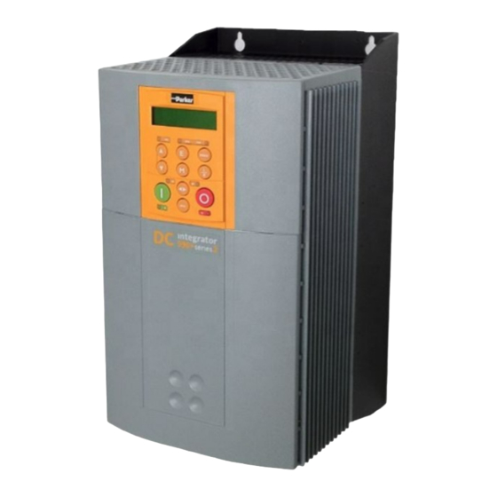
An Overview of the Converter Component Identification 590+ Controller (Frames 1 & 2) Front View (with items Frame 1, 15A unit illustrated Main converter assembly Power terminal shield Terminal cover 10 Power terminals Terminal cover retaining screw 11 Control terminals Blank cover 12 Earthing points 6901 operator station (optional) -
Page 22: Door Assembly (Frames 3, 4, 5 & H)
An Overview of the Converter 590+ Door Assembly (Frames 3, 4, 5 & H) Front View (with items removed) Frames 4 & 5 : Product Code 590PD/..(illustrated) Main door assembly Speed feedback technology card (optional) Terminal cover Control terminals Terminal cover retaining screw Operator station port Blank cover... -
Page 23: Controller (Frame 3)
An Overview of the Converter 590+ Controller (Frame 3) Door Assembly Product Code 590PXD/..270A unit illustrated Main converter assembly Busbars - main power output Door assembly IP20 Top Cover Field wiring terminals IP20 Fan Housing (where fitted) Busbars - main power input 590+ Series DC Digital Converter... -
Page 24: Controller (Frames 4 & 5)
An Overview of the Converter 590+ Controller (Frames 4 & 5) On the Frame 5, both the Master and Slave drives must be individually earthed Frame 4 Frame 5 Door Assembly Product Code 590PD/..field & auxiliary connections via grommet When Frame 5, both terminals are for A+ connections Main converter assembly Auxiliary supply, contactor and motor thermistor terminals... -
Page 25: Product (Frame H)
2-10 An Overview of the Converter 590+ Product (Frame H) Removable Lifting Brackets (4 off) Keyhole Mounting Slots (8 off for 4Q Regenerative) (6 off for 2Q Non-Regenerative) 590+ SERIES EUROTHERM DRIVES Armature terminals are Auxiliary fitted to right hand side Power Power of the drive but can... -
Page 26: Nstalling The
Installing the Converter NSTALLING THE ONVERTER IMPORTANT: Read Chapter 12: “Certification for the Converter” before installing this unit. Refer to “Installation Drawings”, page 3-29 for further information. Mechanical Installation Unpacking the Converter Caution The packaging is combustible and this action may produce lethal toxic fumes. Save the packaging in case of return. -
Page 27: Product Dimensions
Installing the Converter Product Dimensions 180A - 270A 15A - 35A 40A - 165A Frame 3 Frame 1 Frame 2 Current Rating (A) Weight in Kg (lbs) Overall Dimensions Fixing Centres 15 - 35 6.4 (14) 200 (7.9) 375 (14.8) 220 (8.7) 140 (5.5) 360 (14.2) -
Page 28: Mounting The Converter
Installing the Converter Mounting the Converter Note: General installation details are given below for mounting the Converter, however, if you are installing the unit with an EMC filter refer to “External AC Supply EMC Filter Installation”, page 3-27. Mount the unit vertically on a solid, flat, vertical surface. It is mounted using bolts or screws into four fixing points (keyhole slots). -
Page 29: Installing The External Vent Kit (Frames 4 & 5)
Installing the Converter PE/GRD 115V ac 115V ac + 10% 50/60Hz 4.5A Caution PE/GRD 230V ac 230V ac + 10% 50/60Hz 2.25A PE/GRD Figure 3-2 Frame H Fan Wiring Diagram Installing the External Vent Kit (Frames 4 & 5) SSD Part Numbers: Frame 4 : LA466717U001 Frame 5 : LA466717U002 Refer also to Figure 3-18 page 3-34 and Figure 3-20 page 3-36. -
Page 30: Ac Line Choke
Installing the Converter AC Line Choke We recommend that you always use the specified ac line choke with the Converter to provide a known supply impedance for effective operation of the thyristor transient suppression circuits. At least 1% line impedance should be provided in the supply side of the converter. -
Page 31: Frame H Additional Information
Installing the Converter Frame H Additional Information Removing the Cover (Frame H) The cover is manufactured from sheet metal and weighs:- 2Q Non-Regenerative = 10kg (22 lbs) 4Q Regenerative = 15kg (33 lbs) To remove the cover use a flat headed screwdriver to undo the two screws at the base of the cover. -
Page 32: Electrical Installation
Installing the Converter Electrical Installation IMPORTANT: Please read the Safety Information on page Cont. 3 & 4 before proceeding. WARNING! Ensure that all wiring is electrically isolated and cannot be made “live” unintentionally by other personnel. Note: Refer to Chapter 11: “Technical Specifications” for additional Cabling Requirements and Terminal Block Wire Sizes. -
Page 33: Minimum Connection Requirements
Installing the Converter Minimum Connection Requirements IMPORTANT: If in doubt about the connection of the DC motor to the drive, contact SSD Drives. Note: Because of the complexity of showing all possible configurations, this Chapter deals only with a `general purpose’ operation as a basic speed controller. Special wiring options usually form part of a customer-specific system and connection details will be provided separately. -
Page 34: Connection Diagrams
Installing the Converter Connection Diagrams FRAMES 1, 2, 3 & 4 Bold lines indicate "minimum connections" Figure 3-8 Power Connections: Frames 1, 2, 3 & 4 (`general purpose’ configuration) 590+ Series DC Digital Converter... - Page 35 3-10 Installing the Converter FRAME 5 Bold lines indicate "minimum connections" Figure 3-9 Power Connections: Frame 5 (`general purpose’ configuration) Control connections are as Frames 1, 2, 3 & 4. 590+ Series DC Digital Converter...
- Page 36 3-11 Installing the Converter FRAME H Bold lines indicate "minimum connections" Figure 3-10 Power Connections: Frame H (`general purpose’ configuration) 590+ Series DC Digital Converter...
-
Page 37: Power Connections
3-12 Installing the Converter Power Connections 3-Phase Supply, 3-Phase External Contactor Connect the Frame 3: Terminals 3 & 4 = D5 & D6 : Frame H: Terminals 3 & 4 = C & N main ac power to Main AC Power busbar There is no specific phase connection to terminals L1, L2 and L3 as the controller is terminals L1,... - Page 38 Note: If the drive is to operate in regenerating mode for long periods, it is advisable to fit a dc fuse or high speed circuit breaker in the armature star circuit. If in doubt consult SSD Drives. point Motor Field Connect the Frame 3: Terminals F- &...
- Page 39 IMPORTANT: The auxiliary supply terminals must be connected directly to the incoming supply. No series sequencing switches or contacts are permitted without consultation from SSD Drives. Use suitable external fuse protection: the steady state current absorbed by the controller is nominal, the external fuse is determined chiefly by considering the contactor holding VA and the controller cooling fans.
-
Page 40: Control Connections
3-15 Installing the Converter Control Connections Speed Demand Connect a 10k Uni-directional Speed Demand potentiometer This connection provides a Uni-Directional Speed Demand for non-reversing between applications and the 2 Quadrant controller (591+): +10V terminals A1 Ramp Maximum forward speed demand (+100%) = Terminal B3, +10V input and B3. - Page 41 3-16 Installing the Converter Control Connections cont. Program Stop/Coast Stop These connections provide a Program Stop (B8), and a Coast Stop (B9). Connect Refer to Chapter 4: "Starting and Stopping Methods". terminals B8 and B9 to C9 The "Emergency Stop" relay (normally-open, delay on de-energisation) should not be via an part of the normal sequencing system which is implemented via the Start contacts, but is Emergency...
- Page 42 3-17 Installing the Converter Control Connections cont. Drive Healthy This is one of three digital output terminals that provide a +24V dc output signal under Connect certain conditions. They allow for the connection of relays which, in conjunction with terminal C1 to the Enable, Start/Run and Emergency Stop relay, can be used to enhance the safe B6 via a lamp starting and stopping of the controller.
- Page 43 3-18 Installing the Converter Control Connections cont. Analog Outputs User These are configurable outputs and can be used as required in the control system design, connection to i.e. connection to a meter, for cascading to another drive. external Terminal A7, Analog Output 1 provides a Speed Feedback value, -10V to +10V equipment.
- Page 44 The maximum Microtach frequency is 50kHz, thus with a standard 1000 lines per revolution Microtach the motor speed cannot exceed 3000 rpm. For specification and connection information refer to SSD Drives or the appropriate Technical Manual. Wire-Ended Encoder Refer to Chapter 13: “Standard and Optional Equipment” - Optional Equipment for User further information.
-
Page 45: Motor Field Options
3-20 Installing the Converter Motor Field Options WARNING! Isolate the drive before converting to internal/external supply. The FIELD CONTROL function block controls the motor field. The FLD CTRL MODE parameter allows you to select either Voltage or Current Control mode. In Voltage Control mode, the RATIO OUT/IN parameter is used to scale the motor field output voltage as a percentage of the input supply voltage. -
Page 46: Power Board - Pcb Reference 385851 (Frame 3)
3-21 Installing the Converter Internal Motor Field (default for this board) Terminals F+ and F-, the motor field outputs, are energised when the 3-phase supply is connected to L1/L2/L3. Terminals FL1 and FL2 are not required. The internal motor field supply is fused by 10A fuses, FS5 &... -
Page 47: Power Board - Pcb Reference 466701 (Frames 4 & 5)
3-22 Installing the Converter Caution When using an external ac input it is important to have the correct phase relationship on the terminals. The supply must be derived from L1 (Red) and L2 (Yellow) phases directly or indirectly through a single phase transformer. L1 must be connected to D1, and L2 connected to D2. -
Page 48: Dc Contactor - External Va Sensing
3-23 Installing the Converter DC Contactor - External VA Sensing Connections are provided for external armature voltage sensing (at the motor) for when a dc contactor is used between the drive and motor. Power Board - PCB Reference 385851 (Frame 3) EXA+ (F15) EXA-... -
Page 49: External Connections (Frame H)
3-24 Installing the Converter External Connections (Frame H) Motor field supply and and output terminals plus external armature voltage sense MVA+ MVA- busbar busbar contactor power Fuses - only necessary for control local leads longer than 3 metres terminals Locate fuses close to signal N &... -
Page 50: Optional Equipment
3-25 Installing the Converter Optional Equipment Fitting the Remote 6901 Operator Station The 6052 Mounting Kit is required to remote-mount a 6901 Operator Station. It is possible to remote-mount the drive-mounted Operator Station using the port illustrated You can also replace an Operator Station for a PC running ConfigEd Lite (or other suitable PC programming tool) in all of the options above. -
Page 51: Speed Feedback And Technology Options
3-26 Installing the Converter Speed Feedback and Technology Options The Options are: 1. Speed Feedback (Analog Tacho Calibration Option Board or Microtach/Encoder Feedback Option Card) 2. Communications Technology Box (6055 - LINK II, Profibus, DeviceNet, Serial RS485) They are plugged into the two positions, as illustrated. Earthing Screw Speed... -
Page 52: External Ac Supply Emc Filter Installation
3-27 Installing the Converter External AC Supply EMC Filter Installation Refer to Chapter 11: “Technical Specifications” - Environmental Details, and External AC Supply (RFI) Filters and Line Choke for selection details. A filter is used with the Converter to reduce the line conducted emissions produced by the Converter. -
Page 53: Earth Fault Monitoring Systems
This has been minimised in SSD Drives filters, but may still trip out any circuit breaker in the earth system. In addition, high frequency and dc components of earth leakage currents will flow under normal operating conditions. -
Page 54: Installation Drawings
3-29 Installing the Converter Installation Drawings Converter Installation Drawings Figure 3-13 Frame 1 : 15A & 35A Stack Assembly – Drg. No. HG466465 590+ Series DC Digital Converter... - Page 55 3-30 Installing the Converter Figure 3-14 Frame 2 : 40A-165A Stack Assembly 590+ Series DC Digital Converter...
- Page 56 3-31 Installing the Converter Figure 3-15 Frame 3 : 180A Stack Assembly - Drg No. HG466427 590+ Series DC Digital Converter...
- Page 57 3-32 Installing the Converter Figure 3-16 Frame 3 : 270A Stack Assembly - Drg No. HG466428 590+ Series DC Digital Converter...
- Page 58 3-33 Installing the Converter Figure 3-17 Frame 4 : 380-830A Stack Assembly – Drg. No. HG466700U001 590+ Series DC Digital Converter...
- Page 59 3-34 Installing the Converter Figure 3-18 Frame 4 : 380-830A External Vent Kit Installation – Drg No. HG466700U002 590+ Series DC Digital Converter...
- Page 60 3-35 Installing the Converter On the Frame 5, both the Master and Slave drives must be individually earthed Figure 3-19 Frame 5 : 1580A Stack Assembly – Drg No. HG466700U110 590+ Series DC Digital Converter...
- Page 61 3-36 Installing the Converter Figure 3-20 Frame 5 : 1580A External Vent Kit Installation – Drg No. HG466700U111 590+ Series DC Digital Converter...
- Page 62 3-37 Installing the Converter Figure 3-21 Frame H : 1200A-2700A Stack Assembly (Regenerative) - Drg No. HG466432U000/1 590+ Series DC Digital Converter...
- Page 63 3-38 Installing the Converter Figure 3-22 Frame H : 1200A-2700A Stack Assembly (Regenerative) - Drg No. HG466432U000/2 590+ Series DC Digital Converter...
- Page 64 3-39 Installing the Converter Figure 3-23 Frame H : 1200A-2700A Stack Assembly (Non-regenerative) - Drg No. HG466433U000/1 590+ Series DC Digital Converter...
- Page 65 3-40 Installing the Converter Figure 3-24 Frame H : 1200A-2700A Stack Assembly (Non-regenerative) - Drg No. HG466433U000/2 590+ Series DC Digital Converter...
-
Page 66: Filter Installation Drawings
3-41 Installing the Converter Filter Installation Drawings Figure 3-25 Filter Mounting Details, Part No. CO467844U015 for Frame 1 : 15 Amp 590+ Series DC Digital Converter... - Page 67 3-42 Installing the Converter Figure 3-26 Filter Mounting Details, Part No. CO467844U040 for Frame 1: 35 & Frame 2 : 40 Amp 590+ Series DC Digital Converter...
- Page 68 3-43 Installing the Converter Figure 3-27 Filter Mounting Details, Part No. CO467844U070 for Frame 2 : 70 Amp 590+ Series DC Digital Converter...
- Page 69 3-44 Installing the Converter Figure 3-28 Filter Mounting Details, Part No. CO467844U110 for 590+ Frame 2 : 110 Amp 590+ Series DC Digital Converter...
- Page 70 3-45 Installing the Converter Figure 3-29 Filter Mounting Details, Part No. CO467844U165 for Frame 2 : 165 Amp 590+ Series DC Digital Converter...
- Page 71 3-46 Installing the Converter Figure 3-30 Filter Mounting Details, Part No. CO467844U180 for Frame 3 : 180 Amp 590+ Series DC Digital Converter...
- Page 72 3-47 Installing the Converter Figure 3-31 Filter Mounting Details, Part No. CO467843U340 Frame 3 : 270 Amp (1 filter) and Frame 4 : 380-830 Amp (2 filter) (refer to Chapter 11: “Technical Specifications” - External AC Supply (RFI) Filters) 590+ Series DC Digital Converter...
-
Page 73: Line Choke Installation Drawings
3-48 Installing the Converter Line Choke Installation Drawings IMPORTANT: Always use the specified ac line choke with the Converter. 200mm long flying leads SSD Part Number Converter Rating Weight Dimensions (mm) Terminal Hole (kg) Ø Ø For use without EMC Filters Frame 1 CO466448U015 CO466448U040... - Page 74 170 200 280 380 Line Choke (Frames 4, 5 & H) Contact SSD Drives about suitable chokes for the above frame sizes. Also refer to Chapter 11: “Technical Specifications” - AC Line Choke (Frame H). 590+ Series DC Digital Converter...
-
Page 75: Pre-Operation Checks
Operating the Converter PERATING THE ONVERTER Pre-Operation Checks Initial checks before applying power: Mains power supply voltage is correct. Auxiliary power supply voltage is correct. Motor is of correct armature voltage and current rating. Check all external wiring circuits - power, control, motor and earth connections. Note: Completely disconnect the Converter before point-to-point checking with a buzzer, or when checking insulation with a Megger. -
Page 76: Control Philosophy
Operating the Converter Control Philosophy There are four ways to control the Converter using Remote and Local control: 590+ converter 590+ converter 590+ converter 590+ converter using using using using analog and digital Technology inputs and Option outputs Operator to fieldbus, PC running Station LINK II network,... -
Page 77: Selecting Local Or Remote Control
Operating the Converter Selecting Local or Remote Control The default is for the L/R key to be set for Remote control, i.e. both the SEQ and REF LEDs will DEFAULT be off. If the default Remote Start/Stop and Speed Control is not suitable for your application, follow the instructions below using the Operator Station or a suitable PC programming tool to select Local Start/Stop and Speed Control. -
Page 78: Setting-Up The Converter
Operating the Converter Setting-up the Converter The following start-up routine assumes that the Operator Station is fitted and is in default mode, and that the Converter’s control terminals are wired as shown in the Minimum Connection diagrams in Chapter 3. The following instructions are written in logical order. -
Page 79: Selecting Speed Feedback
Operating the Converter FLD.CTRL MODE Set the field control mode to Field Voltage or Field Current control. Refer to Chapter 6: “Programming Your Application” - Field Control for further information. By default, the drive is operating in Voltage Control mode. FLD.VOLTS RATIO FIELD VOLTS Enter the calculated ratio into the parameter given by the equation:... - Page 80 Operating the Converter Calibration for Voltages greater than 200V For full speed tacho voltages greater than 200V, an external resistor, value RE, is required in series with the tachogenerator connection to terminal G3. Set the switches on the Tacho Calibration Option Board to give a value of 200V, as shown opposite.
-
Page 81: Initial Start-Up Routine
Operating the Converter Initial Start-up Routine Complete steps 1 to 18, including steps 16 and 17 as appropriate. Note: This routine assumes that the Converter’s control terminals are wired as shown in the Minimum Connection Requirements drawings in Chapter 3. The field is “Enabled” and is in Voltage Control (default settings). - Page 82 Operating the Converter Step 5 With +24V present at terminals B8 and B9 (Program Stop and Coast Stop): Apply the "Start/Run" command to C3. MMI Menu Map 1 DIAGNOSTICS The main 3-phase contactor should pull-in and remain energised, (it may de-energise almost immediately due to the PROGRAM STOP 3-phase fail alarm).
- Page 83 Operating the Converter If the field voltage is not correct, make the following checks: Step 9.1 Internally Supplied Field: Check that 3-phase is applied to terminals L1, L2 and L3 when the main contactor is closed. MMI Menu Map Check that the coding fuses on the power board or 1 SETUP PARAMETERS suppression board are healthy.
- Page 84 4-10 Operating the Converter Caution During the following set-up instructions, be ready to STOP the converter should the motor try to overspeed. Step 12 Set the Speed Setpoints so that the value of the SPEED MMI Menu Map SETPOINT is about 5%, 0.5V at setpoint input (terminal A8). 1 DIAGNOSTICS Perform the next operation with ARM VOLTS FBK selected for SPEED SETPOINT...
- Page 85 4-11 Operating the Converter WARNING! Do not continue until Step 12 is completed satisfactorily. Step 13 If the drive has run satisfactorily without any need for reconnection of the field or tachogenerator but the direction of rotation is wrong, open the main contactor and disconnect all supplies.
- Page 86 4-12 Operating the Converter Step 16 Adjustment for field weakening: If the drive is to be run with a top speed greater than the base speed then `field weakening’ is used to achieve that top speed. (Refer to Chapter 9: “Control Loops” - Field Control for a more detailed explanation).
-
Page 87: Performance Adjustment
4-13 Operating the Converter Performance Adjustment Current Loop - The Autotune Feature Now perform an Autotune to identify and store the following Current Loop parameters: PROP. GAIN INT. GAIN DISCONTINUOUS Initial Conditions 1. Main contactor open, i.e. no Start/Run signal at terminal C3. 2. - Page 88 4-14 Operating the Converter A Method for Setting-up the PID Gains The gains should be set-up so that a critically damped response is achieved for a step change in setpoint. An underdamped or oscillatory system can be thought of as having too much gain, and an overdamped system has too little.
-
Page 89: Starting And Stopping Methods
4-15 Operating the Converter Starting and Stopping Methods Stopping Methods Note: If the Converter is “non-regenerative” (2-quad - 591+) it effectively coasts to a stop once the current demand reverses. If the Converter is “regenerative” (4-quad - 590+) then it can stop faster because it uses energy from the load, i.e. -
Page 90: Normal Stop (C3)
4-16 Operating the Converter Normal Stop (C3) This is achieved by removing 24V from Terminal C3. MMI Menu Map 1 SETUP PARAMETERS The motor speed is brought to zero in a time defined by the STOP TIME parameter. 2 STOP RATES STOP TIME NORMAL STOP SPEED SETPOINT (100%) - Page 91 4-17 Operating the Converter TIME-OUT IN NORMAL STOP SPEED SETPOINT Control Signals START/RUN (C3) SPEED SETPOINT SPEED DEMAND Speed Demand CONTACTOR WILL DROP OUT IF SPEED FEEDBACK > STOP ZERO SPEED = SPEED SETPOINT WHEN STOP LIMIT TIMED OUT SPEED FEEDBACK Actual Speed STOP ZERO SPEED (DEFAULT 2% )
-
Page 92: Program Stop (B8)
4-18 Operating the Converter Program Stop (B8) MMI Menu Map This is achieved by removing 24V from Terminal B8. 1 SETUP PARAMETERS The motor speed is brought to zero under conditions defined by the PROG. STOP TIME (ramp rate) and PROG. STOP I LIMIT 2 STOP RATES parameters. -
Page 93: Coast Stop (B9)
4-19 Operating the Converter TIME-OUT IN PROGRAM STOP SPEED SETPOINT Control Signals LED ON (PROGRAM STOP FALSE ) PROGRAM STOP SPEED DEMAND SPEED SETPOINT Speed Demand CONTACTOR WILL DROP OUT IF SPEED FEEDBACK SPEED FEEDBACK > STOP ZERO SPEED SPEED SETPOINT WHEN PROG STOP LIMIT TIMED OUT Actual Speed STOP ZERO SPEED... -
Page 94: Normal Starting Method
4-20 Operating the Converter Normal Starting Method To achieve a normal start of the Converter: 1. Apply 24V to Terminal C5 (Enable) 2. Apply 24V to Terminal C3 (Start) Note: The Converter will not start if there are alarms present, or if Terminals B8 (Program Stop) or B9 (Coast Stop) are low, 0V. -
Page 95: Connecting The Operator Station
The Operator Station PERATOR TATION Connecting the Operator Station The Operator Station is a plug-in MMI (Man-Machine Interface) option that allows full use of the Converter’s features. It provides local control of the Converter, monitoring, and complete access for application programming. -
Page 96: Control Key Definitions
The Operator Station Control Key Definitions Keys for Programming the Converter Note: See “Navigating the Menu”, page 5-6 for a quick-start to using the menu. Navigation - Moves upwards through the list of parameters. Parameter - Increments the value of the displayed parameter. Command Acknowledge - Confirms action when in a command menu. -
Page 97: Indications
The Operator Station Indications Operator Station LEDs There are seven LEDs that indicate the status of the Converter. Each LED is considered to operate in three different ways: The LEDs are labelled HEALTH, LOCAL (as SEQ and REF), FWD, REV, RUN, and STOP. FLASH Combinations of these LEDs have the following meanings:... -
Page 98: The Menu System
The Operator Station The Menu System The menu system is divided into a `tree’ structure with 9 “MENU LEVEL” main menus. Consider these main menus to be at Menu Level 1 (refer to the The Menu System Menu System Map on the next page). Parameters contained in Menu Level 1 are the most frequently used, as you descend the menu levels the parameters DIGITAL DC DRIVE... -
Page 99: The Local Menu
The Operator Station The Local Menu There is also a separate Local menu which provides Local Setpoint information. This menu can be accessed from anywhere in the Menu System by pressing the L/R key. Holding the M key down in the Local menu will display additional Feedback information. A toggle to the Local menu displays whichever is in force, Forward or Reverse, previously selected by the FWD/REV key. -
Page 100: Navigating The Menu System
The Operator Station Navigating the Menu System scroll The Menu System can be thought of as a map which is navigated using the four keys shown opposite. exit to next menu/ previous select parameter Keys E and M navigate through the menu menu levels. -
Page 101: The Menu System Map
The Operator Station The Menu System Map MENU LEVEL DIAGNOSTICS MENU LEVEL RAMPS SETUP PARAMETERS AUX I/O OP-STATION SET UP START UP VALUES MENU LEVEL JOG/SLACK PASSWORD LOCAL RAMP RAISE/LOWER PRESET SPEEDS SRAMP RATE SET 0 RATE SET 1 SPECIAL BLOCKS MENU LEVEL ALARM STATUS TENS+COMP CALC. -
Page 102: Menu Shortcuts And Special Key Combinations
The Operator Station Menu Shortcuts and Special Key Combinations Quick Tag Information Hold down the M key for approximately ½ second in any Menu System parameter to display the Tag number for that parameter. RAMP ACCEL TIME 10.0 SECS HOLD RAMP ACCEL TIME TAG NO = 2 Changing the Stack Size (3-button reset) -
Page 103: Resetting To Factory Defaults (2-Button Reset)
The Operator Station This is the preferred way of selecting a new product code. The available product codes are restricted to the set of codes that match the stack that the control board is fitted to. If the product code is changed during the 3-button reset, the following parameters are set to their default value for the new product code: Tag 523 ARMATURE CURRENT... -
Page 104: Special Menu Features
ENGLISH is the default language and is permanently saved (in Read Only Memory). A second language is loaded (typically French), however German, Italian and Spanish are available by contacting SSD Drives. When a new language is downloaded it replaces the current second language. -
Page 105: Password Protection
5-11 The Operator Station Password Protection MMI Menu Map When in force, the password prevents unauthorised parameter modification by making all parameters “read-only”. 1 PASSWORD ENTER PASSWORD If you attempt to modify a password protected parameter, it will cause CHANGE PASSWORD “PASSWORD ??”... -
Page 106: To Deactivate Password Protection
5-12 The Operator Station To Deactivate Password Protection With password protection activated, you can no longer edit the CHANGE PASSWORD parameter until you deactivate the password protection (because the value is hidden by “ **** ”). 1. Enter the current password (e.g. 0x0002) in the ENTER PASSWORD parameter. MENU LEVEL ENTER PASSWORD PASSWORD... -
Page 107: How To Save, Restore And Copy Your Settings
5-13 The Operator Station How to Save, Restore and Copy your Settings Saving Your Application MMI Menu Map SYSTEM CONFIGURE I/O 1 SYSTEM 2 CONFIGURE I/O CONFIGURE I/O CONFIGURE ENABLE ENABLED ▲ ▼ CONFIGURE I/O DISABLED SYSTEM CONFIGURE I/O The PARAMETER SAVE menu, available in both the full and reduced MMI Menu Map view levels, is used to save any changes you make to the MMI settings. -
Page 108: Programming With Block Diagrams
Programming with Block Diagrams You can program the Converter for specific applications using the MMI or suitable programming tool, such as “ConfigEd Lite” which is SSD Drives’ block programming software. The Converter is supplied with a basic set-up which can be used as a starting point for application-specific programming. -
Page 109: Programming Rules
0.00V Some parameters are indicated as “Reserved”, Tag Number these parameters are for use Default Value by SSD Drives' engineers. Input Parameter Name Figure 6-1 Function Block Parameter Information Function Name Names the function block Default Value The default value of the unmodified factory set-up... -
Page 110: Mmi Menu Maps
Programming Your Application MMI Menu Maps MMI Menu Map The function block descriptions include an easy-find menu showing the menu levels and 1 SYSTEM titles encountered to find the appropriate menu title, and the parameters contained in the menu(s). 2 CONFIGURE I/O The menu maps are shown as if the full view level is selected. -
Page 111: Function Block Descriptions
Programming Your Application Function Block Descriptions Note: Remember to select the correct mode, Setup or Configuration, whilst editing. Refer to “Modifying a Block Diagram”, page 6-1. You must select the full view level to see all of the function blocks (go to the MENUS menu at level 1 on the MMI). Function Block Page Function Block... -
Page 112: Analog Inputs
Programming Your Application ANALOG INPUTS The analog input block is used to scale and clamp the inputs for terminals A2 to A6. MMI Menu Map 1 SYSTEM Analog Input 1 Analog Input 2 OUTPUT [246] – 100 OUTPUT [493] – 0.00 % 2 CONFIGURE I/O 1.0000 –... - Page 113 Programming Your Application ANALOG INPUTS Functional Description Configurable Analog Inputs CALIBRATION MAX VALUE OUTPUT MIN VALUE DIAGNOSTIC 590+ Series DC Digital Converter...
-
Page 114: Analog Outputs
Programming Your Application ANALOG OUTPUTS This function block converts the demand percentage into 0-10V, suitable for driving the MMI Menu Map analog output electronics of the drive. 1 SYSTEM 2 CONFIGURE I/O Analog Output 2 Analog Output 1 63 – [252] INPUT 62 –... -
Page 115: Aux I/O
Programming Your Application AUX I/O The auxiliary I/O parameters are primarily MMI Menu Map Aux I/O intended to extend the functionality of the START (C3) [ 68] – OFF 1 SETUP PARAMETERS DIGIN (C4) [ 69] – OFF serial links by allowing them access to the DIGIN (C5) [ 70] –... - Page 116 Programming Your Application AUX I/O Parameter Range AUX DIGOUT 1 OFF / ON Software digital output 1. For example, to directly drive the configurable digital output DIGOUT1, connect the Source of DIGOUT1 to this parameter, Tag 94. AUX DIGOUT 2 OFF / ON Software digital output 2.
- Page 117 6-10 Programming Your Application AUX I/O Functional Description AUX I/O DEFAULT TAG # PARAMETER SETTING 161 AUX START START 227 AUX JOG 168 AUX ENABLE ENABLE CONFIGURABLE AUX I/O POINTS NOTE (1) 94 AUX DIGOUT 1 95 AUX DIGOUT 2 96 AUX DIGOUT 3 0.00% 128 ANOUT 1...
- Page 118 6-11 Programming Your Application AUX I/O Useful Commands using EI Bisynch ASCII - REM. SEQUENCE Tag 536, Mnemonic "ow", for example: /Remote Alarm Start Enable Command Trip Mode Start Drive ow>0203 Stop Drive ow>0201 Disable Drive ow>0200 Jog Setpoint 1 ow>0205 Jog Setpoint 2 ow>020D...
- Page 119 6-12 Programming Your Application AUX I/O Drive Enable To Enable the drive in remote mode the following diagnostic must be TRUE: REM.SEQ.ENABLE[535] and REM SEQUENCE [536] BIT 1. Drive Start To Start the drive in remote mode the following diagnostic must be TRUE: REM.SEQ.ENABLE[535] and REM SEQUENCE [536] BIT 0.
-
Page 120: Block Diagram (Mmi Only)
6-13 Programming Your Application BLOCK DIAGRAM (MMI only) Use this menu to execute the named function blocks. MMI Menu Map 1 SYSTEM The parameters in Block Diagram connect the outputs of RAISE/LOWER, RAMPS, SETPOINT SUM 1, and the Special Blocks (MMI menu) function blocks to destinations as 2 CONFIGURE I/O required. -
Page 121: Calibration
6-14 Programming Your Application CALIBRATION This function block contains motor- MMI Menu Map Calibration specific parameters. TERMINAL VOLTS [ 57] – 0.00% 1 SETUP PARAMETERS TACH INPUT (B2) [ 58] – 0.0% When CONFIGURE ENABLE = TRUE, 2 CALIBRATION ENCODER [ 59] – 0 RPM the operation of the Block Diagram is CONFIGURE ENABLE suspended and all Operator Station LEDs... - Page 122 FIELD CURRENT parameter (CONFIGURE DRIVE function block). POSITION COUNT 0x0000 to 0xFFFF Reserved parameter for use by SSD Drives. The POSITION COUNT and POSITION DIVIDER parameters allow basic position control using a PLC (programmable logic controller), the optional COMMS techbox, and a speed feedback encoder mounted on the motor shaft.
- Page 123 6-16 Programming Your Application CALIBRATION Functional Description CALIBRATION DEFAULT PARAMETER TAG# SETTING 0.00% ZERO SPD. OFFSET ENCODER LINES 0001 1000 RPM TO SPEED LOOP ENCODER RPM SPEED FEEDBACK SELECTION ENCODER ENCODER INTERFACE OPTION PCB 1.0000 ANALOG TACH CAL TECHNOLOGY TACH INPUT (B2) OPTION 1.0000 ARMATURE V CAL.
-
Page 124: Configure Drive
0 : ARM VOLTS FBK 1 : ANALOG TACH 2 : ENCODER 3 : ENCODER/ANALOG - for SSD Drives use ENCODER RPM 0 to 6000 RPM Motor top speed setting (100%) when using encoder feedback. - Page 125 6-18 Programming Your Application CONFIGURE DRIVE Parameter Range CONFIGURE ENABLE DISABLED / ENABLED Selects Setup Mode (DISABLED) or Configuration Mode (ENABLED). Refer to “Modifying a Block Diagram”, page 6-1. MAIN CURR. LIMIT Refer to CURRENT LOOP, page 6-19. AUTOTUNE Refer to CURRENT LOOP, page 6-19. INT.
-
Page 126: Current Loop
Turns the AUTOTUNE procedure on. Refer to Chapter 4: "Operating the Converter" - Performance Adjustment. ILOOP SUSPEND FALSE / TRUE Reserved parameter for use by SSD Drives. MASTER BRIDGE OFF / ON A diagnostic indicating currently active bridge; master = ON, slave = OFF. - Page 127 6-20 Programming Your Application CURRENT LOOP Parameter Range INT. GAIN 0.00 to 200.00 Integral gain control for armature current PI loop, set during the autotune function. FEED FORWARD 0.10 to 50.00 Set by Autotune but not used by the default I-Loop mode. DISCONTINUOUS 0.00 to 200.00 % Sets the boundary between the discontinuous and continuous regions of the current signal.
- Page 128 6-21 Programming Your Application CURRENT LOOP Parameter Range CUR. LIMIT/SCALER 0.00 to 200.00 % (CUR.LIMIT/SCALER) Current limit scaler. It scales bipolar/unipolar clamps. To achieve 200% current limit, the current limit scaler should be set to 200%. CURRENT LOOP FROM FROM CURRENT INVERSE TIME PROFILE...
-
Page 129: Current Profile
6-22 Programming Your Application CURRENT PROFILE Use this to clamp the current limit for applications MMI Menu Map Current Profile where motors have a reduced ability to commutate 100.0 % – [ 32] SPD BRK 1 (LOW) 1 SETUP PARAMETERS 100.0 % –... -
Page 130: Diagnostics
6-23 Programming Your Application DIAGNOSTICS This block contains MMI Menu Map MMI Menu Map cont. Diagnostics parameters used to SPEED FEEDBACK [207] – 0.00 % DIAGNOSTICS DIAGNOSTICS SPEED ERROR [297] – 0.00 % monitor the status of SPEED DEMAND UNFIL.TACH INPUT CURRENT DEMAND [299] –... - Page 131 6-24 Programming Your Application DIAGNOSTICS The MMI DIAGNOSTICS Menu Many more signals can be monitored using the MMI display. The diagnostic parameters are "read-only" and are very useful for tracing configuration problems. Parameter Range SPEED DEMAND Speed loop total setpoint after the ramp-to-zero (Refer to STOP RATES, page 6-83) block.
- Page 132 6-25 Programming Your Application DIAGNOSTICS Parameter Range RAMPING FALSE / TRUE The SETPOINT ramp function block is limiting the (Refer to RAMPS, page 6-63) rate of change of Speed Setpoint. PROGRAM STOP FALSE / TRUE State of program stop (Terminal B8). When B8 is at (Refer to STOP RATES, page 6-83) 24V, then PROGRAM STOP is FALSE.
- Page 133 6-26 Programming Your Application DIAGNOSTICS Parameter Range ANIN 2 (A3) xxx.xx VOLTS Hardwired. Speed setpoint no. 2 or current demand (Refer to ANALOG INPUTS, if C8 = ON. page 6-5) ANIN 3 (A4) xxx.xx VOLTS Speed setpoint no. 3 (ramped). (Refer to ANALOG INPUTS, page 6-5) ANIN 4 (A5)
- Page 134 6-27 Programming Your Application DIAGNOSTICS Parameter Range PID OUTPUT xxx.xx% Output of the PID function block. (Refer to PID, page 6-55) PID CLAMPED FALSE / TRUE Indicates the PID output has reached either the (Refer to PID, page 6-55) positive or negative limit. PID ERROR xxx.xx% Displays the difference between the setpoint...
- Page 135 6-28 Programming Your Application DIAGNOSTICS Parameter Range DRIVE RUNNING FALSE / TRUE Drive is enabled and may make current when (DIAGNOSTIC only) TRUE. A diagnostic for those parameters that can only be written to when the drive is stopped (parameters marked with Note 2 in the Parameter Specification Table).
-
Page 136: Diameter Calc
6-29 Programming Your Application DIAMETER CALC. This block is used to calculate roll MMI Menu Map Diameter Calc. diameters in winder applications. DIAMETER [427] – 0.00 % SETUP PARAMETERS MOD OF LINE SPEED [428] – 0.00 % The block is ignored by the drive unless the MOD OF REEL SPEED [429] –... - Page 137 6-30 Programming Your Application DIAMETER CALC. Parameter Range REEL SPEED -105.00 to 105.00 % This will usually be configured to be the drive's own speed feedback, i.e. encoder or armature volts feedback. MIN DIAMETER 0.00 to 100.00 % Set to the minimum core diameter (normally the empty core diameter) as a percentage of the maximum roll diameter.
-
Page 138: Digital Inputs
6-31 Programming Your Application DIGITAL INPUTS Use this block to control the digital operating parameters of the software. MMI Menu Map 1 SYSTEM Digital Input 1 Digital Input 2 OUTPUT [102] – 90 OUTPUT [105] – 118 2 CONFIGURE I/O 0.01 % –... - Page 139 6-32 Programming Your Application DIGITAL INPUTS Inverting the Input Signal The default setting is for VALUE TRUE to be 0.01% and VALUE FALSE to be 0.00%. Inverting the digital input is therefore simple; set VALUE TRUE to 0.00% and VALUE FALSE to 0.01% (or any other non-zero number).
- Page 140 6-33 Programming Your Application DIGITAL INPUTS DIGITAL INPUT C5 Refer to the DIAGNOSTICS function block description, page 6-23. Caution If you are isolating power on the drive output using a DC contactor, you must use an auxiliary, normally-open contact connected to terminal C5 to immediately disable the drive's current loop when the contactor coil de- energises.
-
Page 141: Digital Outputs
6-34 Programming Your Application DIGITAL OUTPUTS This function block allows you to output digital parameters within the software to other MMI Menu Map equipment. 1 SYSTEM Digout 1 (B5) Digout 2 (B6) 2 CONFIGURE I/O 122 – [ 98] INPUT 77 –... - Page 142 6-35 Programming Your Application DIGITAL OUTPUTS Digital Output Examples Using Digital Outputs with LOGIC Parameters Logic parameters have values of 1/0: TRUE/FALSE, ON/OFF, ENABLED/DISABLED etc. For example, the (logic) default connections in the drive allow the Digital Outputs to provide (source) 24V or 0V dc depending upon the state of following tag connections: Terminal B5, Digital Output 1 is linked to Tag Number 77 (AT ZERO SPEED) Terminal B6, Digital Output 2 is linked to Tag Number 122 (HEALTH LED)
-
Page 143: Field Control
6-36 Programming Your Application FIELD CONTROL This function block contains all MMI Menu Map Field Control the parameters for the field FIELD ENABLED [169] – DISABLED 1 SETUP PARAMETERS FIELD DEMAND [183] – 0.00 % operating mode. FLD. FIRING ANGLE [184] –... - Page 144 6-37 Programming Your Application FIELD CONTROL Parameter Range FIELD ENABLED DISABLED / ENABLED Refer to the DIAGNOSTICS function block description, page 6-23. FIELD DEMAND xxx.xx % Refer to the DIAGNOSTICS function block description, page 6-23. FLD. FIRING ANGLE xxx.xx DEG (FLD.FIRING ANGLE) Refer to the DIAGNOSTICS function block description, page 6-23.
- Page 145 6-38 Programming Your Application FIELD CONTROL Parameter Range EMF LAG 0.00 to 200.00 This is the lag time constant adjustment of the field weakening PID loop With a default of 4.00, real time constant = 4000ms. EMF GAIN 0.00 to 100.00 This is the gain adjustment of the field weakening PID loop.
- Page 146 6-39 Programming Your Application FIELD CONTROL FIELD CONTROL DEFAULT TAG# PARAMETER SETTING FIELD ENABLE ENABLED OUTPUT IN VOLTAGE MODE: NOTE (2) FLD VOLTAGE VARS SUPPLY RATIO FIELD OUTPUT RATIO OUT/IN 90.00% 460V 410V FIELD 460V 300V AC VOLTAGE 230V 200V [VF (AC) RMS] 230V 150V...
-
Page 147: Inertia Comp
6-40 Programming Your Application INERTIA COMP This function block directly compensates MMI Menu Map Inertia Comp for load inertia during acceleration. INERTIA COMP OUTPUT [602] – 0.00 % 1 SETUP PARAMETERS UNSCALED OUTPUT [603] – 0.00 % DELTA [601] – 0.00 % This is particularly useful in high accuracy 2 SPEED LOOP 0.00 –... -
Page 148: Inhibit Alarms
6-41 Programming Your Application INHIBIT ALARMS This allows you to disable certain MMI Menu Map Alarms alarms and leave drive operation READY [125] – FALSE 1 SETUP PARAMETERS HEALTHY [122] – TRUE un-interrupted if the related fault HEALTH WORD [115] – 0x0000 2 INHIBIT ALARMS occurs. - Page 149 6-42 Programming Your Application INHIBIT ALARMS Parameter Range LAST ALARM See below The hexadecimal value of the last (or only) alarm. Refer to Chapter 7: “Trips and Fault Finding” - Alarm Messages. 0x0000 : NO ACTIVE ALARMS 0x0001 : OVER SPEED 0x0002 : MISSING PULSE 0x0004 : FIELD OVER I 0x0008 : HEATSINK TRIP...
- Page 150 6-43 Programming Your Application INHIBIT ALARMS Parameter Range ENCODER ALARM ENABLED / INHIBITED Inhibits the encoder option board alarm. REM TRIP INHIBIT ENABLED / INHIBITED Inhibits the remote trip. REM TRIP DELAY 0.1 to 600.0 SECS The delay between the remote trip alarm being activated and the drive tripping. Functional Description INHIBIT ALARMS TO ALARM STATUS...
-
Page 151: Internal Links
6-44 Programming Your Application INTERNAL LINKS Use internal links to connect an internal input to an internal output, and to connect an MMI Menu Map input terminal to multiple destinations. 1 SYSTEM Link 11 Link 12 2 CONFIGURE I/O OUTPUT DEST [391] – 0 OUTPUT DEST [396] –... - Page 152 6-45 Programming Your Application INTERNAL LINKS LINKS 11 & 12 Special links 11 and 12 allow further functionality within the block diagram by using three additional parameters: ADVANCED, AUX SOURCE and MODE. They can perform seven functions, depending upon the values of the MODE and ADVANCED parameters. Parameter Range OUTPUT DEST...
- Page 153 6-46 Programming Your Application INTERNAL LINKS Functional Description The following diagram shows the internal schematic for a special link. Link 11 & Link 12 Mode Inverter Switch Aux Source Sign Chg Modulus Comparator Dest Source Advanced 590+ Series DC Digital Converter...
- Page 154 6-47 Programming Your Application INTERNAL LINKS Internal Links - Example Controlling both the acceleration and deceleration times of the drive ramp through analog input 1 (default terminal A2) This example is similar to the first example in ANALOG INPUTS, page 6-5. As before, the ends of the external potentiometer are connected to the drive's 0V and +10V dc supply (terminals A1 and B3).
-
Page 155: Jog/Slack
6-48 Programming Your Application JOG/SLACK This block can be used to provide jog, take MMI Menu Map Jog/Slack up slack and crawl speed functions. OPERATING MODE [212] – STOP 1 SETUP PARAMETERS 5.00 % – [218] JOG SPEED 1 The inputs to this block are the Start and Jog -5.00 % –... - Page 156 6-49 Programming Your Application JOG/SLACK Functional Description Note: The setpoint column in the table below refers to the Ramp Input ONLY, as indicated in the table. Any "direct" setpoints present will also add to this setpoint to make the total speed setpoint.
-
Page 157: Menus
6-50 Programming Your Application MENUS Use this block to select either the full MMI menu MMI Menu Map Menus structure, or a reduced menu structure for easier ENABLED – [ 37] FULL MENUS MENUS ENGLISH – [304] LANGUAGE navigation. FULL MENUS LANGUAGE You can also select the display language for the MMI. -
Page 158: Minilink
6-51 Programming Your Application miniLINK These parameters are general purpose tags. MMI Menu Map miniLINK 0.00 % – [339] VALUE 1 1 SYSTEM By using a VALUE or LOGIC as a staging post, a 0.00 % – [340] VALUE 2 function block destination may be connected to a 2 miniLINK 0.00 % –... -
Page 159: Op Station
(OP STATION ERROR) SETPOINT JOG SETPOINT The last communication error. FORWARD Reserved parameter for use by SSD Drives. PROGRAM LOCAL KEY ENABLE FALSE / TRUE LOCAL Enables the LOCAL/REMOTE control key on the op-station. Set to TRUE to allow the MMI Menu Map operator to toggle between local and remote modes. - Page 160 6-53 Programming Your Application OP STATION Functional Description Local Setpoint Local Ramp Stop Ramp Up Key Down Key Accel Time Reset Value Decel Time % S-Ramp Local Setpoint (only active when the drive is in Local mode) 590+ Series DC Digital Converter...
-
Page 161: Password (Mmi Only)
Parameter Range CHANGE PASSWORD ENTER PASSWORD 0x0000 to 0xFFFF Default = 0x0000. BY-PASS PASSWORD FALSE / TRUE Default = FALSE Reserved parameter for use by SSD Drives. CHANGE PASSWORD 0x0000 to 0xFFFF Default = 0x0000. 590+ Series DC Digital Converter... -
Page 162: Pid
6-55 Programming Your Application This is a general purpose PID block which MMI Menu Map can be used for many different closed loop PID OUTPUT [417] – 0.00 % 1 SETUP PARAMETERS PID CLAMPED [416] – FALSE control applications. PID ERROR [415] –... - Page 163 6-56 Programming Your Application Parameter Range O/P SCALER (TRIM) -3.0000 to 3.0000 (O/P SCALER(TRIM)) The ratio that the limited PID output is multiplied by in order to give the final PID Output. Normally this ratio would be between 0 and 1. INPUT 1 -300.00 to 300.00 % PID setpoint input.
- Page 164 6-57 Programming Your Application Functional Description The following block diagram shows the internal structure of the PID block. PID is used to control the response of any closed loop system. It is used specifically in system applications involving the control of drives to allow zero steady state error between Reference and Feedback, together with good transient performance.
- Page 165 6-58 Programming Your Application Derivative Gain Derivative gain instantaneously boosts the PID output signal. Increasing DERIVATIVE TC decreases the damping, which in most cases causes overshoot and oscillations resulting in an unacceptable system response. Note: For most applications, derivative gain is never used and is usually left at its default value of 0.000 seconds.
-
Page 166: Preset
6-59 Programming Your Application PRESET The Preset block allows you to select one of MMI Menu Map Preset eight preset inputs, which in turn may be PRESET OP (%) [572] – 0.00 % 1 SETUP PARAMETERS OUTPUT [593] – 0.0 connected to other blocks of inputs. - Page 167 6-60 Programming Your Application PRESET Functional Description INPUT 0 INPUT 1 OUTPUT INPUT 2 INPUT 3 100% PRESET OP % INPUT 4 MAX SPEED INPUT 5 INPUT 6 INPUT 7 INVERT O/P SELECT 1 SELECT 2 SELECT 3 Selection Table Three Boolean variables used to select between one of the 8 preset values.
-
Page 168: Raise/Lower
6-61 Programming Your Application RAISE/LOWER This function block acts as an internal MMI Menu Map Raise/Lower motorised potentiometer (MOP). OUTPUT [264] – 0.00 % 1 SETUP PARAMETERS 0.00 % – [255] RESET VALUE This block is ignored by the drive unless 10.0 s –... - Page 169 6-62 Programming Your Application RAISE/LOWER Functional Description EXTERNAL RESET RAISE INPUT LOWER INPUT RAISE INPUT TRUE FALSE RAISE/LOWER INPUT 100% 100% RAISE/LOWER RESET VALUE INCREASE RATE DECREASE RATE OUTPUT % DEFAULT=0.00% DEFAULT 10.0 SEC DEFAULT 10.0 SEC The diagram above illustrates the raise/lower functionality. When EXTERNAL RESET is set TRUE, the raise/lower output resets to RESET VALUE (default = 0.00%).
-
Page 170: Ramps
6-63 Programming Your Application RAMPS Ramps The RAMPS parameters set the shape and MMI Menu Map RAMP OUTPUT [ 85] – 0.00 % duration of the ramp used for starting and 1 SETUP PARAMETERS RAMPING [113] – FALSE changing speeds. 10.0 s –... - Page 171 The deceleration time for 100% change. CONSTANT ACCEL DISABLED / ENABLED Reserved parameter for use by SSD Drives. RAMP HOLD OFF / ON When ON, the ramp output is held at its last value. This is overridden by a ramp reset.
- Page 172 6-65 Programming Your Application RAMPS Parameter Range EXTERNAL RESET DISABLED / ENABLED When ENABLED, the ramp is reset to RESET VALUE. EXTERNAL RESET does not depend on AUTO RESET for its operation. RESET VALUE -300.00 to 300.00 % The ramp output value at power-up, or when the ramp is reset. In order to catch a spinning load smoothly (`bumpless transfer’) connect SPEED FEEDBACK Tag No.
- Page 173 6-66 Programming Your Application RAMPS ACCELERATION/DECELERATION RATES RAMP INPUT (+ 100%) +100% RAMP OUTPUT RAMP DECEL TIME RAMP ACCEL TIME (S RAMP 0%) (S RAMP 0%) ACTUAL ACCEL TIME ACTUAL DECEL TIME WITH S RAMP WITH S RAMP RAMP INPUT (-100%) RAMP OUTPUT -100% RAMP ACCEL TIME...
- Page 174 6-67 Programming Your Application RAMPS AUTO RESET 100% DRIVE ENABLED DRIVE ENABLED RAMP INPUT = X% DRIVE DISABLED RAMP INPUT % 100% = RAMP INPUT X % RAMP OUTPUT RAMP OUTPUT % When AUTO RESET is ENABLED, ramp output resets to RESET VALUE each time the drive is enabled.
-
Page 175: Setpoint Sum 1
6-68 Programming Your Application SETPOINT SUM 1 Use this block to sum and scale up to three MMI Menu Map Setpoint Sum 1 analog inputs to produce the SPT. SUM SPT. SUM [ 86] – 0.00 % 1 SETUP PARAMETERS 1.0000 –... -
Page 176: Setpoint Sum 2
6-69 Programming Your Application SETPOINT SUM 1 Parameter Range LIMIT 0.00 to 200.00 % The Setpoint Sum programmable limit is symmetrical and has the range 0.00% to 200.00%. The limit is applied both to the intermediate results of the RATIO calculation and the total output. - Page 177 6-70 Programming Your Application SETPOINT SUM 2 Setpoint Sum 2 is a general purpose MMI Menu Map Setpoint Sum 2 summing and ratio block that allows two SPT SUM OUTPUT [451] – 0.00 % 1 SETUP PARAMETERS OUTPUT 0 [491] – 0.00 % scalable inputs and one unscalable input to OUTPUT 1 [492] –...
- Page 178 6-71 Programming Your Application SETPOINT SUM 2 Functional Description RATIO 0 [447] INPUT 0 [444] OUTPUT 0 [491] DIVIDER 0 [448] MAIN OUTPUT [451] INPUT 2 [445] RATIO 1 [446] INPUT 1 [443] OUTPUT 1 [492] DIVIDER 1 [466] LIMIT [449] 590+ Series DC Digital Converter...
-
Page 179: Speed Loop
6-72 Programming Your Application SPEED LOOP Use this block to tune the speed loop PI MMI Menu Map Speed Loop to produce a current demand. OUTPUT [356] – 0.00 % 1 SETUP PARAMETERS SPEED FEEDBACK [ 62] – 0.00 % The speed loop has four inputs: SPEED SETPOINT [ 63] –... - Page 180 SPD FBK FILTER. A value of 0.5 equates to a filter time of 4.8ms, 0.8 to 14.7ms, and 0.9 to 31.2ms. ENCODER FILTER See below Reserved parameter for use by SSD Drives. SETPOINT 1 -105.00 to 105.00 % Speed Setpoint 1 (Default Setpoint Sum 1 O/P).
- Page 181 6-74 Programming Your Application SPEED LOOP Parameter Range PRESET TORQUE -200.00 to 200.00 % The PRESET TORQUE is pre-loaded into the speed loop integral store as the speed loop in enabled. This is scaled by PRESET T SCALE. This may be used to pre-load the output of the speed loop in elevator/hoist applications to prevent the load from falling back when the brake is released.
- Page 182 6-75 Programming Your Application SPEED LOOP SPEED LOOP NOTE [1] TO CURRENT LOOP SETPOINTS (I DEMAND ISOLATE SWITCH) DEFAULT TAG# PARAMETER SETTING 7 RATIO 2 (A3) 1,0000 ANALOG I/P 2 FROM CURRENT LOOP I DMD ISOLATE 9 SIGN 2 (A3) POSITIVE 290 SETPOINT 2 FROM...
-
Page 183: Speed Loop (Advanced)
6-76 Programming Your Application SPEED LOOP (ADVANCED) Contains parameters for the advanced user. MMI Menu Map Advanced These parameters change the proportional and 0 – [268] MODE 1 SETUP PARAMETERS 1.00 % – [269] SPD BRK 1 (LOW) integral profiles, and can disable SCR/thyristor 5.00 % –... - Page 184 (particularly high inertia loads). POS. LOOP P GAIN -200.00 to 200.00 % Reserved parameter for use by SSD Drives. Not recommended for new applications. ZERO SPD. LEVEL 0.00 to 200.00 % Sets the threshold of SPEED DEMAND and SPEED FEEDBACK for suspending the current output.
-
Page 185: Sramp
Threshold for AT SPEED diagnostic output. OVER SHOOT -100.00 to 100.00 % THRESHOLD (OVERSHOOT THRESH) Reserved parameter for use by SSD Drives. ERROR THRESHOLD -100.00 to 100.00 % Hysterisis level before s-ramp operates. Reserved parameter for use by SSD Drives. - Page 186 6-79 Programming Your Application SRAMP Parameter Range ACCEL 0 0.00 to 100.00 % Acceleration rate, in units of percent per second . i.e. 75.00 % means that the maximum acceleration will be 75.00% per second if the full speed of the machine is 1.25ms then the acceleration will be 1.25 * 75.0% = 0.9375ms DECEL 0 0.00 to 100.00 %...
- Page 187 6-80 Programming Your Application SRAMP Useful Equations Note: These only hold true if Jerk = Jerk2 for acceleration or Jerk 3 = Jerk 4 for deceleration. V is the maximum speed the drive must reach. In % / sec A is the maximum allowable acceleration in %/sec J is the maximum allowable value for jerk, in %/sec The time needed to stop or accelerate is: [Seconds]...
-
Page 188: Standstill
ZERO SETPOINT 0 to 639 (SOURCE TAG) Do not alter. Reserved parameter for use by SSD Drives. STANDSTILL LOGIC DISABLED / ENABLED If ENABLED, the Converter is quenched (although the contactor remains in) when the Speed Feedback and Speed Setpoint values are less than ZERO THRESHOLD. - Page 189 6-82 Programming Your Application STANDSTILL STANDSTILL ENABLED DISABLED STANDSTILL LOGIC SPEED FEEDBACK SPEED CURVE DEPENDS ON LOAD SETPOINT CHARACTERISTICS ZERO THRESHOLD (DEFAULT = 2.00%) SPEED FEEDBACK % ENABLED ENABLED DISABLED DRIVE ENABLE STANDSTILL DEFAULT TAG# PARAMETER SETTING 11 STANDSTILL LOGIC DISABLED DRIVE ENABLE SPEED...
-
Page 190: Stop Rates
6-83 Programming Your Application STOP RATES These parameters are used by a regenerative MMI Menu Map Stop Rates drive when stopping with Normal Stop or SPEED DEMAND [ 89] – 0.00 % 1 SETUP PARAMETERS PROGRAM STOP [ 80] – FALSE Program Stop. - Page 191 6-84 Programming Your Application STOP RATES Parameter Range CONTACTOR DELAY 0.1 to 600.0 s This defines the time the contactor stays energised for after the STOP ZERO SPEED limit is reached. Maintain zero speed during contactor delay. CURR DECAY RATE 0.00 to 200.00 This is the rate at which the current is quenched when the current loop is disabled.
- Page 192 6-85 Programming Your Application STOP RATES SPEED TO/FROM SPEED LOOP SPEED DEMAND SETPOINT STOP RATES DEFAULT TAG# PARAMETER SETTING STOP TIME 10.0 SECS RAMP TO ZERO RAMP TO ZERO TO CURRENT LOOP 0.1 SECS PROG STOP TIME CURRENT LIMIT SWITCH PROG STOP I LIM 100.00% TO COAST...
-
Page 193: System Port P3
(PC) running a serial communications program, or on-line 2 SYSTEM PORT (P3) (while the drive is running) when using the SSD Drives 5703 Setpoint Repeater Unit. 3 P3 SETUP You can also use the P3 port to transfer configuration files by connecting to a PC running the Windows compatible software package "ConfigEd Lite". -
Page 194: 5703 Support
6-87 Programming Your Application 5703 SUPPORT This function block contains the parameters MMI Menu Map 5703 for connecting a SSD Drive 5703 Setpoint SCALED INPUT [189] – 0.00 % 1 SERIAL LINKS RAW INPUT [187] – 0.00 % Repeater Unit. 89 –... -
Page 195: Taper Calc
6-88 Programming Your Application TAPER CALC. Use this block to profile the tension demand MMI Menu Map Taper Calc. with diameter. TAPERED DEMAND [452] – 0.00 % 1 SETUP PARAMETERS TOT. TENS DEMAND [441] – 0.00 % This block is ignored by the drive unless 0.00 % –... - Page 196 6-89 Programming Your Application TAPER CALC. Parameter Range TAPERED DEMAND xxx.xx % This is the output of the TAPER calculation on the TENSION SPT (before adding TENSION TRIM). TOT. TENS DEMAND xxx.xx % (TOT.TENS.DEMAND) This is the final output of this block (total tension demand) which can be connected to the appropriate points in the block diagram.
-
Page 197: Tec Option
6: VERSION NUMBER older than Version 2.x If the VERSION NUMBER error message is displayed, the Technology Option is using software that doesn’t fully support the drive; refer to SSD Drives. VERSION 0x0000 to 0xFFFF (TEC OPTION VER) The version of the Technology Option. -
Page 198: Tens+Comp Calc
6-91 Programming Your Application TENS+COMP CALC. This block provides additional torque to MMI Menu Map Tension & Comp compensate for static and dynamic friction, TENS+COMP [478] – 0 1 SETUP PARAMETERS INERTIA COMP O/P [485] – 0.00 % as well as the load inertia. 0.00 % –... - Page 199 6-92 Programming Your Application TENS+COMP CALC. Parameter Range TENS+COMP 0 to 639 (TENS+COMP CALC.) The sum of the diameter-scaled TENSION DEMAND after the TENSION SCALER scaling and the compensation losses. For open loop winder applications, connect this output to the TORQUE DEMAND (Tag 432) in the TORQUE CALC. function block. (This output is located in the SYSTEM::CONFIGURE I/O::BLOCK DIAGRAM menu).
- Page 200 6-93 Programming Your Application TENS+COMP CALC. Tension Scaler [486] Tension & Demand Torque Demand Diameter* (Internal Variable) Static Comp [487] |Nw|* Total Torque Demand Dynamic Comp [488] [478] TENS+COMP Rewind (Forward) [489] [479] Fixed Inertia Comp [485] Inertia Comp Output Variable Inertia Comp [480] Roll Width/Mass...
-
Page 201: Torque Calc
6-94 Programming Your Application TORQUE CALC. This block switches the drive between Speed and MMI Menu Map Torque Calc. Tension mode. It also switches the current limits POS. I CLAMP [435] – 0 1 SETUP PARAMETERS NEG. I CLAMP [436] – 0 as required for over and under winding. -
Page 202: User Filter
A noisy signal that requires smoothing is connected to INPUT. The OUTPUT is connected to the destination function block. Parameter Range INPUT -300.00 to 300.00 % Reserved parameter for use by SSD Drives. OUTPUT xxx.xx % Reserved parameter for use by SSD Drives. 590+ Series DC Digital Converter... -
Page 203: Trips
Trips and Fault Finding RIPS AND AULT INDING Trips What Happens when a Trip Occurs When a trip occurs, the Converter’s power stage is immediately disabled causing the motor and load to coast to a stop. The trip is latched until action is taken to reset it. This ensures that trips due to transient conditions are captured and the Converter is disabled, even when the original cause of the trip is no longer present. -
Page 204: Fault Finding
Converter fuse keeps Faulty cabling or connections Check for problem and rectify before blowing wrong replacing with correct fuse Faulty Converter Contact SSD Drives Cannot obtain Incorrect or no supply Check supply details HEALTH state available Motor will not run at... - Page 205 Trips and Fault Finding Adaptor Board Current Calibration Switch (Frame 3) NO POWER IS CONNECTED AT THIS STAGE View the switch with the terminal cover removed: IA CAL - Armature Current Calibration Switch This switch is always set to "1" (ON). Power Board Current Calibration Switches (Frames 4 &...
- Page 206 Trips and Fault Finding IA CAL - Armature Current Calibration switches 1 to 4 are always set to “ON”, and 5 to 6 are always set to “OFF”. Armature Voltage Calibration switch SW10 is always set to "OFF". IF CAL - Field Current For field currents greater than 20A, set the Field Current calibration switches 8 and 9 to give the required Field Current range.
-
Page 207: Alarm Messages
Trips and Fault Finding Alarm Messages When a trip occurs an alarm message is displayed on the MMI, and information about the trip is stored in the ALARM STATUS menu. The alarm message and the LAST ALARM parameter are displayed in the selected language of the MMI. -
Page 208: Hexadecimal Representation Of Trips
Trips and Fault Finding Hexadecimal Representation of Trips The LAST ALARM, HEALTH WORD and HEALTH STORE parameters use a four digit hexadecimal number to identify individual trips. Each trip has a unique corresponding number as shown below. LAST ALARM, HEALTH WORD and HEALTH STORE Trip Trip Code First Digit... -
Page 209: Power Board Led Trip Information (Frame 4, 5 & H)
Trips and Fault Finding Power Board LED Trip Information (Frame 4, 5 & H) The HEATSINK TRIP, 3 PHASE FAILED and ACCTS FAILED trips are associated with the following LED indications: Frame 4 Check the LEDs on the power board for more HEATSINK TRIP information. The LEDs light to indicate a problem. -
Page 210: Using The Mmi To Manage Trips
Trips and Fault Finding Using the MMI to Manage Trips Trip Messages Most of the alarms have a delay timer so that the Converter only trips if the condition persists for the whole of the delay period. If the Converter trips, then the display immediately shows a message indicating the reason for the trip. - Page 211 Trips and Fault Finding Trip Message and Meaning Possible Reason for Trip SPEED FEEDBACK The difference between speed feedback Analog tacho feedback polarity incorrect (terminals and armature voltage feedback is G3 and G4) greater than the SPDFBK ALM LEVEL The ENCODER SIGN parameter’s polarity is incorrect parameter value Disconnection of wiring, including fibre optics Tachogenerator failure...
- Page 212 6.6ms is acceptable) Motor armature windings failure - check insulation resistance. Badly tuned current loop Faulty Converter - refer to SSD Drives ACCTS FAILED AC current transformer plug connection Check armature current transformer plug for correct to Converter power board missing installation.
-
Page 213: Symbolic Alarm Messages
7-11 Trips and Fault Finding Symbolic Alarm Messages These are generally internal software or hardware. If these should occur please investigate, or contact SSD Drives Technical Support. Number Description Action 0xF003 Pre-Ready Fault Coding not present. Replace power board or chassis. -
Page 214: Viewing Trip Conditions
The following test points are located on the control board and can be accessed through the Technology Option housing. When used with a meter, they will provide valuable information in the event of a fault. Refer to SSD Drives for further information. Technology Box... -
Page 215: Maintenance
Routine Maintenance and Repair OUTINE AINTENANCE AND EPAIR Maintenance Because of its solid state design, the 590+ Digital drive has few items requiring service or maintenance. Service typically is a matter of replacing fuses, checking electrical contacts, and isolating problems in the overall system application. Caution Service procedures must be performed by qualified personnel with an understanding of the dangers inherent in high voltage applications and the precautions necessary when... -
Page 216: Returning The Unit To Ssd Drives
Routine Maintenance and Repair Returning the Unit to SSD Drives Before calling SSD Drives Customer Service, make sure you have the following information available: Information Source Model number and serial number 590+Digital drive rating label Motor horsepower, armature current and... -
Page 217: Technical Support Checks
Routine Maintenance and Repair Technical Support Checks The results of the following checks will be very useful to SSD Drives’ Technical Support. Caution Please only attempt these checks if you are electrically competent. Miscellaneous Checks Check 24V present at Terminals C1 to C9 (C1 is 0V) - dc Check 10V present at Terminals B3 and B4 (B1 is 0V) - dc Check auxiliary supply present at Neutral &... -
Page 218: Fuse Replacement (Frame H)
Routine Maintenance and Repair Fuse Replacement (Frame H) 1. Remove the front cover. 2. Unplug the ribbon cables to the trigger boards. 3. Open the swing-frame using the two quick-release fixings at the right hand end. 590+ 4Q Product (Regenerative) FRONT VIEW SIDE VIEW Phase Assembly... -
Page 219: Product (Non-Regenerative)
Routine Maintenance and Repair In-Situ Replacement Procedure 1. Disconnect the relevant fuse microswitch assembly by unplugging the lead assembly from the rear trunking. 2. Remove the M12 screw (A), and the 4 screws (F, G, H, I). Remove the CT plate and handles. -
Page 220: Phase Assembly Replacement (Frame H)
Routine Maintenance and Repair 5. Reverse the procedure for re-fitting. Phase Assembly Replacement (Frame H) Phase Assembly Dummy Board (one only shown for clarity) Busbar Stack of interconnecting plates Trigger Board (one only shown for clarity) (upper phase assemblies only shown) Phase Assembly Thyristor Suppression... - Page 221 Routine Maintenance and Repair Phase Assembly Removal Procedure 1. Referring to Figure 8-1 (590+) or Figure 8-2 (591+), remove the M12 screw (A). Undo the four screws (B, C, D, E) which allows the CT plate and fuse assembly to be removed. 2.
-
Page 222: Replacing The Fan (Frames 4 & 5)
Routine Maintenance and Repair Replacing the Fan (Frames 4 & 5) WARNING! Ensure that all wiring is electrically isolated and cannot be made “live” unintentionally by other personnel. Remove the terminal cover. Unscrew the three screws securing the baffle and remove. Disconnect the fan supply cable. -
Page 223: Principle Of Operation
Control Loops ONTROL OOPS Principle of Operation Note: Selection between Current Control or Speed Control (default) is MMI Menu Map made by the I DMD ISOLATE (current demand isolate) parameter 1 SETUP PARAMETERS using Digital I/P3 (Terminal C8). If ENABLED the Converter operates as a current controller, and if DISABLED (the default) it 2 CURRENT LOOP operates as a speed controller. -
Page 224: Manual Tuning
In order to disable this alarm the special "super- password" reserved for SSD Drives personnel needs to be entered. Next in the "Reserved" menu, which will then appear as a submenu of "SYSTEM", a parameter called SYS HEALTH INHIB should be set to the hexadecimal value 0x0002. - Page 225 Control Loops Subsequently either a squarewave signal should be applied to the current demand input (Terminal A3) with Current Demand Isolate (terminal C8) on or "toggle" between two values of current limit into terminal A6 and operate in normal speed loop mode.
-
Page 226: Speed Loop
Please refer to SSD Drives Engineering Department for assistance in the use of this feature. Current Demand Rate Limit (di/dt) Access to the di/dt limit is currently reserved for SSD Drives personnel only in the Reserved Menu. This is a limit imposed on the rate of change of the current demand. It is to be used for motors with commutation limitations, mechanical systems that cannot absorb rapid torque transients and also as a means of limiting current overshoot for large current swings (e.g. -
Page 227: Current Control
Control Loops Current Control The field current loop can accept a demand directly from the plant and/or an outside field weakening loop and forms the error signal which is the difference between demand and feedback. The error signal is fed into a P + I compensator which produces the output of the field loop, i.e. - Page 228 10-1 Parameter Specification Table ARAMETER ABLES The headings for the Tag No. table are described below. A numeric identification of the parameter. It is used to identify the source and destinations of internal links. Name The parameter name as it appears on the MMI. MMI Menu The menu page under which the parameter is stored on the MMI.
-
Page 229: Specification Table: Tag Number Order
10-2 Parameter Specification Table Specification Table: Tag Number Order Name MMI Menu CE Block Range Notes NONVOL VERSION 0x0000 to 0xFFFF RAMP ACCEL TIME SETUP PARAMETERS::RAMPS Ramps 0.1 to 600.0 SECS RAMP DECEL TIME SETUP PARAMETERS::RAMPS Ramps 0.1 to 600.0 SECS CONSTANT ACCEL SETUP PARAMETERS::RAMPS Ramps... - Page 230 10-3 Parameter Specification Table Name MMI Menu CE Block Range Notes AT CURRENT LIMIT DIAGNOSTICS Current Loop Output MODULUS SYSTEM::CONFIGURE I/O::DIGITAL Digout 1 (B5) 0:FALSE OUTPUTS::DIGOUT 1 (B5) 1:TRUE MODULUS SYSTEM::CONFIGURE I/O::DIGITAL Digout 2 (B6) Same as Tag 43 OUTPUTS::DIGOUT 2 (B6) MODULUS SYSTEM::CONFIGURE I/O::DIGITAL Digout 3 (B7)
- Page 231 10-4 Parameter Specification Table Name MMI Menu CE Block Range Notes NEG. I CLAMP DIAGNOSTICS Diagnostics Output SPEED DEMAND DIAGNOSTICS Stop Rates Output BIPOLAR CLAMPS SETUP PARAMETERS::CURRENT LOOP Current Loop Same as Tag 4 PROG STOP I LIM SETUP PARAMETERS::STOP RATES Stop Rates 0.00 to 200.00 % ENCODER ALARM...
- Page 232 10-5 Parameter Specification Table Name MMI Menu CE Block Range Notes 130 MODE SERIAL LINKS::SYSTEM PORT (P3)::P3 System Port P3 0:DISABLED SETUP 1:5703 MASTER 2:5703 SLAVE 3:EIASCII 131 DEADBAND WIDTH SETUP PARAMETERS::SETPOINT SUM 1 Setpoint Sum 1 0.00 to 100.00 % 132 SETPT.
- Page 233 10-6 Parameter Specification Table Name MMI Menu CE Block Range Notes 186 FLD. QUENCH MODE SETUP PARAMETERS::FIELD CONTROL Field Control 0:QUENCH 1:STANDBY 187 RAW INPUT SERIAL LINKS::SYSTEM PORT (P3)::P3 5703 -300.00 to 300.00 % SETUP::5703 SUPPORT 188 OVER SPEED LEVEL SETUP PARAMETERS::CALIBRATION Calibration 0.00 to 200.00 %...
- Page 234 10-7 Parameter Specification Table Name MMI Menu CE Block Range Notes 225 CRAWL SPEED SETUP PARAMETERS::JOG/SLACK Jog/Slack -100.00 to 100.00 % 226 PEAK HW OFFSET RESERVED Reserved 0 to 20000 227 AUX JOG SETUP PARAMETERS::AUX I/O Aux I/O Same as Tag 18 228 MODE SETUP PARAMETERS::JOG/SLACK Jog/Slack...
- Page 235 10-8 Parameter Specification Table Name MMI Menu CE Block Range Notes 261 RAISE INPUT SETUP PARAMETERS::RAISE/LOWER Raise/Lower Same as Tag 43 262 LOWER INPUT SETUP PARAMETERS::RAISE/LOWER Raise/Lower Same as Tag 43 263 STALL THRESHOLD SETUP PARAMETERS::CALIBRATION Calibration 0.00 to 200.00 % 264 RAISE/LOWER O/P DIAGNOSTICS Raise/Lower...
- Page 236 10-9 Parameter Specification Table Name MMI Menu CE Block Range Notes 301 POS. I CLAMP SETUP PARAMETERS::CURRENT LOOP Current Loop -200.00 to 200.00 % 302 CONTACTOR DELAY SETUP PARAMETERS::STOP RATES Stop Rates 0.1 to 600.0 SECS 304 LANGUAGE Menus 0:0 : ENGLISH;1 : Other 1:0 : ENGLISH;1 : Other 305 TRIP RESET SETUP PARAMETERS::INHIBIT ALARMS...
- Page 237 10-10 Parameter Specification Table Name MMI Menu CE Block Range Notes 356 TOTAL I DMD RESERVED Speed Loop Output,2,4 357 MAX DEMAND SETUP PARAMETERS::SPEED Speed Loop 0.00 to 105.00 % LOOP::SETPOINTS 358 MIN DEMAND SETUP PARAMETERS::SPEED Speed Loop -105.00 to 105.00 % LOOP::SETPOINTS 359 INVERTED SYSTEM::CONFIGURE I/O::DIGITAL...
- Page 238 10-11 Parameter Specification Table Name MMI Menu CE Block Range Notes 393 MODE SYSTEM::CONFIGURE I/O::INTERNAL Link 11 0:SWITCH LINKS::LINK 11 1:INVERT 2:AND 3:OR 4:SIGN CHANGER 5:MODULUS 6:COMPARATOR 394 AUX.SOURCE SYSTEM::CONFIGURE I/O::INTERNAL Link 11 0 to 639 LINKS::LINK 11 395 SOURCE TAG SYSTEM::CONFIGURE I/O::INTERNAL Link 12 0 to 639...
- Page 239 10-12 Parameter Specification Table Name MMI Menu CE Block Range Notes 424 LINE SPEED SETUP PARAMETERS::SPECIAL Diameter Calc. -105.00 to 105.00 % BLOCKS::DIAMETER CALC. 425 MIN DIAMETER SETUP PARAMETERS::SPECIAL Diameter Calc. 0.00 to 100.00 % BLOCKS::DIAMETER CALC. 426 MIN SPEED SETUP PARAMETERS::SPECIAL Diameter Calc.
- Page 240 10-13 Parameter Specification Table Name MMI Menu CE Block Range Notes 454 SOURCE TAG SYSTEM::CONFIGURE I/O::INTERNAL Link 5 0 to 639 LINKS::LINK 5 455 DESTINATION TAG SYSTEM::CONFIGURE I/O::INTERNAL Link 5 0 to 639 LINKS::LINK 5 456 SOURCE TAG SYSTEM::CONFIGURE I/O::INTERNAL Link 6 0 to 639 LINKS::LINK 6...
- Page 241 10-14 Parameter Specification Table Name MMI Menu CE Block Range Notes 486 TENSION SCALER SETUP PARAMETERS::SPECIAL Tension & Comp -3.0000 to 3.0000 BLOCKS::TENS+COMP CALC. 487 STATIC COMP SETUP PARAMETERS::SPECIAL Tension & Comp -300.00 to 300.00 % BLOCKS::TENS+COMP CALC. 488 DYNAMIC COMP SETUP PARAMETERS::SPECIAL Tension &...
- Page 242 10-15 Parameter Specification Table Name MMI Menu CE Block Range Notes 510 PRODUCT CODE 0:INVALID 1,2,3 1:DC 4Q 15A 2:DC 2Q 15A 3:DC 4Q 35A 4:DC 2Q 35A 5:DC 4Q 40A 6:DC 2Q 40A 7:DC 4Q 55A 8:DC 2Q 55A 9:DC 4Q 70A 10:DC 2Q 70A 11:DC 4Q 90A...
- Page 243 10-16 Parameter Specification Table Name MMI Menu CE Block Range Notes 510 PRODUCT CODE 71:DC 4Q 2700A 60 D 1,2,3 72:DC 2Q 2700A 60 D 73:DC 4Q 1200A 80 D 74:DC 2Q 1200A 80 D 75:DC 4Q 1700A 80 D 76:DC 2Q 1700A 80 D 77:DC 4Q 2200A 80 D 78:DC 2Q 2200A 80 D...
- Page 244 10-17 Parameter Specification Table Name MMI Menu CE Block Range Notes 535 REM.SEQ.ENABLE SETUP PARAMETERS::AUX I/O Aux I/O Same as Tag 43 536 REM.SEQUENCE SETUP PARAMETERS::AUX I/O Aux I/O 0x0000 to 0xFFFF 537 SEQ STATUS SETUP PARAMETERS::AUX I/O Aux I/O Output 538 CURRENT FBK.AMPS DIAGNOSTICS...
- Page 245 10-18 Parameter Specification Table Name MMI Menu CE Block Range Notes 582 AUTO RESET SETUP PARAMETERS::SRAMP Same as Tag 43 583 EXTERNAL RESET SETUP PARAMETERS::SRAMP Same as Tag 43 584 RESET VALUE SETUP PARAMETERS::SRAMP -100.00 to 100.00 % 585 QUENCH SETUP PARAMETERS::SRAMP Same as Tag 43 586 AT SPEED LEVEL...
-
Page 246: Parameter Table: Mmi Menu Order
10-19 Parameter Specification Table Parameter Table: MMI Menu Order FACTORY DEFAULTS |__MENU |__D D IAGNOSTICS |__[089] SPEED DEMAND |__[207] SPEED FEEDBACK |__[297] SPEED ERROR |__[549] SPEED LOOP O/P |__[299] CURRENT DEMAND |__[298] CURRENT FEEDBACK |__[538] CURRENT FBK.AMPS |__[065] IaFbk UNFILTERED |__[066] IaDmd UNFILTERED |__[087] POS. - Page 247 10-20 Parameter Specification Table |__[206] ENCODER |__[059] UNFIL.ENCODER |__[062] UNFIL.SPD.FBK |__[064] UNFIL.SPD.ERROR |__[083] CONTACTOR CLOSED |__[122] HEALTH LED |__[125] READY |__[376] DRIVE RUNNING |__[374] SYSTEM RESET |__S S ETUP PARAMETERS |__R R AMPS |__[002] RAMP ACCEL TIME |__[003] RAMP DECEL TIME |__[004] CONSTANT ACCEL Reserved |__[118] RAMP HOLD...
- Page 248 10-21 Parameter Specification Table |__P P RESET SPEEDS |__[560] SELECT 1 |__[561] SELECT 2 |__[562] SELECT 3 |__[563] INVERT O/P |__[559] MAX SPEED |__[600] LIMIT |__[610] GRAY SCALE |__[564] INPUT 0 |__[565] INPUT 1 |__[566] INPUT 2 |__[567] INPUT 3 |__[568] INPUT 4 |__[569] INPUT 5 |__[570] INPUT 6...
- Page 249 10-22 Parameter Specification Table |__[489] REWIND |__[479] FIX.INERTIA COMP |__[480] VAR.INERTIA COMP |__[481] ROLL WIDTH/MASS |__[498] LINE SPEED SPT |__[482] FILTER T.C. |__[483] RATE CAL |__[484] NORMALISED dv/dt |__[485] INERTIA COMP O/P |__[486] TENSION SCALER |__D D IAMETER CALC. |__[424] LINE SPEED |__[437] REEL SPEED |__[425] MIN DIAMETER |__[426] MIN SPEED...
- Page 250 10-23 Parameter Specification Table |__[031] SPD BRK2 (HIGH) |__[093] IMAX BRK1(SPD1) |__[033] IMAX BRK2(SPD2) |__I I NVERSE TIME |__[204] AIMING POINT Reserved |__[199] DELAY Reserved |__[200] RATE Reserved |__S S TOP RATES |__[027] STOP TIME |__[217] STOP LIMIT |__[302] CONTACTOR DELAY |__[594] CURR DECAY RATE |__[026] PROG STOP TIME |__[216] PROG STOP LIMIT...
- Page 251 10-24 Parameter Specification Table |__A A DAPTION |__[268] MODE |__[269] SPD BRK1 (LOW) |__[270] SPD BRK2 (HIGH) |__[271] PROP. GAIN |__[272] SPD.INT.TIME |__[274] I GAIN IN RAMP |__[273] POS. LOOP P GAIN Reserved |__Z Z ERO SPD. QUENCH |__[284] ZERO SPD. LEVEL |__[285] ZERO IAD LEVEL |__I I NERTIA COMP |__[556] INERTIA...
- Page 252 10-25 Parameter Specification Table |__[508] TEC OPTION OUT 1 |__[509] TEC OPTION OUT 2 |__S S YSTEM PORT (P3) |__P P 3 SETUP |__[130] MODE |__5 5 703 SUPPORT |__[132] SETPT. RATIO |__[133] SETPT. SIGN |__[187] RAW INPUT |__[189] SCALED INPUT |__B B ISYNCH SUPPORT |__[329] GROUP ID (GID) |__[330] UNIT ID (UID)
- Page 253 10-26 Parameter Specification Table |__[362] MODULUS |__[464] OFFSET |__[251] SOURCE TAG |__A A NOUT 2 (A8) |__[248] % TO GET 10V |__[363] MODULUS |__[465] OFFSET |__[252] SOURCE TAG |__D D IGITAL INPUTS |__D D IGITAL INPUT C4 |__[494] DESTINATION TAG |__D D IGITAL INPUT C5 |__[495] DESTINATION TAG |__D D IGIN 1 (C6)
- Page 254 10-27 Parameter Specification Table |__[370] SOURCE TAG |__[371] DESTINATION TAG |__L L INK 5 |__[454] SOURCE TAG |__[455] DESTINATION TAG |__L L INK 6 |__[456] SOURCE TAG |__[457] DESTINATION TAG |__L L INK 7 |__[458] SOURCE TAG |__[459] DESTINATION TAG |__L L INK 8 |__[460] SOURCE TAG |__[461] DESTINATION TAG...
- Page 255 10-28 Parameter Specification Table |__[280] HF C/O DISC GAIN Reserved |__[281] HF C/O FILTER TC Reserved |__[282] BEMF THRESHOLD Reserved |__[265] ANALOG IP OFFSET Reserved |__[388] SYNC OFFSET Reserved |__[205] dI/dt Reserved |__[336] CHANGEOVER BIAS Reserved |__[471] STANDBY FIELD Reserved |__[476] 3-PHASE FIELD Reserved |__[550] ENABLE 12 PULSE...
- Page 256 10-29 Parameter Specification Table |__[210] FLD.VOLTS RATIO |__[421] MAIN CURR. LIMIT |__[018] AUTOTUNE |__[047] SPEED FBK SELECT |__[024] ENCODER LINES |__[022] ENCODER RPM |__[049] ENCODER SIGN |__[013] SPD.INT.TIME |__[014] SPD.PROP.GAIN 590+ Series DC Digital Converter...
-
Page 257: Specifications
11-1 Technical Specifications ECHNICAL PECIFICATIONS Environmental Details Operating Temperature Frame 1 : 0 C to +45 C Frame 2 : 0 C to +45 C Frame 3 : 0 C to +45 C Frame 4 : 0 C to +40 C Frame 5 : 0 C to +40 C Frame H :... -
Page 258: Electrical Ratings - Power Circuit
11-2 Technical Specifications Electrical Ratings - Power Circuit Refer to Chapter 3: “Earth Fault Monitoring Systems” for circuit breaker details. Motor HP ratings as NEC Table 430-147: “Full Load Current in Amperes, DC Motors”’ Output Current Output Current Power Motor HP Field Total Losses Symmetrical Fault... -
Page 259: Power Supply Details
11-3 Technical Specifications Power Supply Details 3-Phase Supply LV Build All Frames 110-220V ac ±10%, 50/60Hz 5%, line-to-line, ground referenced (TN) and non-ground referenced (IT) MV Build All Frames 220-500V ac ±10%, 50/60Hz 5%, line-to-line, ground referenced (TN) (standard) and non-ground referenced (IT) HV Build Frame 4 500-600V ac ±10%, 50/60Hz... -
Page 260: Ac Line Choke (Frames 1, 2, 3, 4 & 5)
Table 11 using only a 50 H line choke. Capacitors must be fitted between phase and earth to achieve conformance. Armature Current Rating (A) AC Rating (A) Inductance (μH) SSD Drives Part No. 500Vac 600Vac 500Vac 600Vac For use without filters (use with capacitors for armature currents <100A, refer to Chapter 3: "AC Line Choke") Frame 1 13.5... -
Page 261: Ac Line Choke (Frame H)
Frame 3 1 off CO467844U180 1 off CO467843U340 Frame 4 2 off CO467843U340 2 off CO467843U340 3 off CO467843U340 3 off CO467843U340 Frame 5 1580 (please contact SSD Drives) Frame H 1200-2700 (please contact SSD Drives) 590+ Series DC Digital Converter... -
Page 262: Power Semiconductor Protection Fuses (Frames 1, 2, 3, 4 & 5)
11-6 Technical Specifications Power Semiconductor Protection Fuses (Frames 1, 2, 3, 4 & 5) For fuses where compliance to UL Standards are required, refer to Chapter 12: “Installing the Converter” – Requirements for UL Compliance. Controller Line Fuse Rating SSD Part No. Fuse I²t @ 600V Thyristor I²t Rating... -
Page 263: Power Supply Fuses
11-7 Technical Specifications Power Supply Fuses Power Board Identification Fuse Rating SSD Part No. Frame 1 AH466407 (terminal board) FS1, 5x20mm glass slow-blow CH540033 (for auxiliary supply, contactor, fan supply) Frame 2 AH470330 FS1, 5x20mm glass slow-blow CH540033 (for auxiliary supply, contactor, fan supply) Frame 3 AH385851 FS1, 5x20mm glass slow-blow... -
Page 264: Terminal Definitions (Digital/Analog Inputs & Outputs)
11-8 Technical Specifications Terminal Definitions (Digital/Analog Inputs & Outputs) User inputs/outputs are IEC1131 compliant. Digital Input Rated Voltage: 24V dc Off Region: minimum -3V, maximum 5V input voltage minimum not defined, maximum 15mA input current Transition Region: minimum 5V, maximum 15V input voltage minimum 0.5mA, maximum 15mA input current... -
Page 265: Terminal Information - Power Board (Frames 1, 2, 3, 4 & 5)
11-9 Technical Specifications Terminal Information - Power Board (Frames 1, 2, 3, 4 & 5) Note that on Frame 1 and 2 units, L1, L2, L3, A+ and A- terminals are located on a separate Terminal Board. On Frame 3, 4 & 5 units, they are busbar connections. Frame 3 units have terminal designations D1 to D8, shown in brackets in the Terminal Number column of this table. - Page 266 11-10 Technical Specifications Terminal Information - Power Board (Frames 1, 2, 3, 4 & 5) Note that on Frame 1 and 2 units, L1, L2, L3, A+ and A- terminals are located on a separate Terminal Board. On Frame 3, 4 & 5 units, they are busbar connections. Frame 3 units have terminal designations D1 to D8, shown in brackets in the Terminal Number column of this table.
- Page 267 11-11 Technical Specifications Terminal Information - Power Board (Frames 1, 2, 3, 4 & 5) Note that on Frame 1 and 2 units, L1, L2, L3, A+ and A- terminals are located on a separate Terminal Board. On Frame 3, 4 & 5 units, they are busbar connections. Frame 3 units have terminal designations D1 to D8, shown in brackets in the Terminal Number column of this table.
-
Page 268: Terminal Information - Control Board
11-12 Technical Specifications Terminal Information – Control Board This Control Board is common to all 590+ units. Terminal Terminal Function Signal Level Configurable Terminal Description Number TERMINAL BLOCK A 0V (Signal) Zero Volt Reference Analog Input 1 Speed Setpoint No. 1 +10V = Full speed setpoint forward -10V = Full speed setpoint reverse Analog Input 2... - Page 269 11-13 Technical Specifications Terminal Information – Control Board This Control Board is common to all 590+ units. Terminal Terminal Function Signal Level Configurable Terminal Description Number TERMINAL BLOCK B 0V (Signal) Zero Volt Reference Not Connected Not Connected +10V DC User +10V Reference +10V at 10mA short circuit protected Reference...
-
Page 270: Terminal Information - Control Board
11-14 Technical Specifications Terminal Information – Control Board This Control Board is common to all 590+ units. Terminal Terminal Function Signal Level Configurable Terminal Description Number TERMINAL BLOCK C 0V (Signal) Zero Volt Reference External Trip Input An external interlock or External permissive element should be permissive. -
Page 271: Terminal Information - Control Board
11-15 Technical Specifications Terminal Information – Control Board This Control Board is common to all 590+ units. Terminal Terminal Function Signal Level Configurable Terminal Description Number TERMINAL BLOCK C continued Digital Input 2 Ramp Hold +24V = True/Hold If the input is held true the 0V = False/Ramp S-Ramp output is frozen at Threshold + 16V... -
Page 272: Terminal Information (Frame H)
11-16 Technical Specifications Terminal Information (Frame H) These terminals are located externally on the product. Terminal Terminal Function Terminal Description Number Three phase supply Drive supply L1 - L3 Armature + Drive output to motor armature Armature - Drive output to motor armature External field supply External single phase ac Line 1 input to field bridge. -
Page 273: Terminal Information - Option Boards
11-17 Technical Specifications Terminal Information – Option Boards Terminal Terminal Function Signal Level Terminal Description Number TERMINAL BLOCK G (SWITCHABLE TACHO CALIBRATION OPTION) AC Tacho input AC Tacho input + DC Tacho input - DC Tacho input Tacho Out Calibrated Tacho Output (5701 MICROTACH RECEIVE OPTION - PLASTIC) Signal Input Microtach fibre optic input... -
Page 274: Wire Sizes And Termination Tightening Torques (Frames 1, 2, 3, 4 & 5)
11-18 Technical Specifications Wire Sizes and Termination Tightening Torques (Frames 1, 2, 3, 4 & 5) Power cables must have a minimum rating of 1.1 x full load current - EUROPE Control wiring must have a minimum cross-section area of 0.75mm (18AWG) EUROPE Maximum Tightening... -
Page 275: Termination Tightening Torque (Frame H)
11-19 Technical Specifications Termination Tightening Torque (Frame H) Description Fixings Spanner Size Format Torque Nm Drive Mounting Fixings 19mm Bolt 57.2 Ground studs on back panel 17mm 32.8 Fuse assy to Phase assy 17mm Bolt AC Input & DC Output Bus bars 19mm Nut &... -
Page 276: Spares List
CM466762U002 AH470372U002 CURRENT AH465315U001 CM466762U002 * Do not attempt to upgrade by fitting a later software version Control Board. You may experience hardware compatiblity problems. If in doubt, contact SSD Drives. Frame 1 Product Power Board Terminal Board Armature Field Bridge Fan... - Page 277 11-21 Technical Specifications Frame 3 Fitted with the 590PXD Door Assembly LA466454U001 containing the Control Board and Adaptor Board AH466405U001 Product Power Board Armature Thyristor Field Bridge Fan 115V Fan 230V 591P/0180/220/ AH385851U004 CF057366U014 CF057273U014 DL043707 DL056383 590P/0180/220/ AH385851U005 CF057366U014 CF057273U014 DL043707 DL056383...
- Page 278 11-22 Technical Specifications Frame 4 Fitted with the 590PD Door Assembly LA466454U002 containing the Control Board Product Field Thyristor Field Diode Fan + Capacitor Fan + Capacitor Assembly Assembly 230V 115V 591P/0380/220/ CF385522U016 CW464320U016 LA466711U001 LA466711U002 590P/0380/220/ CF385522U016 CW464320U016 LA466711U001 LA466711U002 591P/0500/220/ CF385522U016...
- Page 279 11-23 Technical Specifications Frame H Fitted with the 590PXD Door Assembly LA466454U001 containing the Control Board and Adaptor Board AH466405U001 Product Power Board Trigger Board Suppression Board Snubber Board 591P/1200/500/ AH466001U101 AH466003U001 AH466003U003 AH466004U001 590P/1200/500/ AH466001U101 AH466003U001 AH466004U001 591P/1700/500/ AH466001U101 AH466003U001 AH466003U003 AH466004U001...
-
Page 280: Requirements For Emc Compliance
ONVERTER Caution The integration of this product into other apparatus or systems is not the responsibility of SSD Drives, with respect to applicability, effectivity, or safety of operation of the other apparatus or systems. Requirements for EMC Compliance All Variable Speed Drives (VSDs) potentially produce electrical emissions which are radiated into the environment and conducted back into the ac supply. -
Page 281: Control/Signal Emc Earth Connections
12-2 Certification for the Converter Control/Signal EMC Earth Connections For compliance with EN60204 and EMC requirements, the “0V/signal ground” must be separately earthed. When a number of units are used in a system, these terminals should be connected together at a single, local earthing point. Control and signal cables for the encoder, all analogue inputs, and communications require screening with the screen connected only at the VSD end. -
Page 282: Emc Installation Options
12-3 Certification for the Converter EMC Installation Options The unit, when installed for Class A operation, will be compliant with EN55011 (1991)/ EN55022 (1994) for radiated emissions, as described below. Screening & Earthing (cubicle mounted, Class A) Note: The installation requirements of local safety standards must be achieved regarding the safety of electrical equipment for machines. -
Page 283: Star Point Earthing
12-4 Certification for the Converter Star Point Earthing A star-point earthing policy separates `noisy’ and `clean’ earths. Four separate earth busbars (three are insulated from the mounting panel) connect to a single earth point (star point) near the incoming safety earth from the main supply. Flexible, large cross-section cable is used to ensure a low HF impedance. - Page 284 12-5 Certification for the Converter Sensitive Equipment The proximity of the source and victim circuit has a large effect on radiated coupling. The electromagnetic fields produced by VSDs falls off rapidly with distance from the cabling/cubicle. Remember that the radiated fields from EMC compliant drive systems are measured at least 10m from the equipment, over the band 30-1000MHz.
-
Page 285: Requirements For Ul Compliance
12-6 Certification for the Converter Requirements for UL Compliance Motor Overload Protection Note: An external motor overload protective device must be provided by the installer. The maximum internal overload protection level (current limit) is 150% for 30 seconds and 200% for 10 seconds. Motor overload protection is provided by means of the thermal device in the motor winding. -
Page 286: Field Wiring Temperature Rating
12-7 Certification for the Converter Output Ratings Short Circuit Rating (kW ) 500V RMS Symmetrical Amperes 5,000 5,000 10,000 10,000 10,000 10,000 18000 18000 30000 30000 1580 85000 Table 12-2 Short Circuit Ratings Field Wiring Temperature Rating Use 75 C copper conductors only. Operating Ambient Temperature For the operating ambient temperature range, refer to Chapter 11: “Technical Specifications”. -
Page 287: Recommended Wire Sizes (Frames 1, 2, 4 & 5)
12-8 Certification for the Converter Recommended Wire Sizes (Frames 1, 2, 4 & 5) Main power wiring. Local wiring regulations always take precedence. Input Output Drive Input Number of North American Output Number of North American Size Current Conductors Wire Size Current Conductors Wire Size... -
Page 288: Standard Equipment
13-1 Standard and Optional Equipment TANDARD AND PTIONAL QUIPMENT Standard Equipment Power Board Circuit Descriptions AH470280U001, U002, U003, U004 (Frame 1) (2 Quad and 4 Quad) Power supplies for the controller are generated from the single phase auxiliary supply via a Switched Mode Power Supply. - Page 289 13-2 Standard and Optional Equipment CONN 1 (to power board) field fuses aux. supply fuse Figure 13-2 Terminal Board - AH466407 (Frame 1) TERMINAL BOARD POWER BOARD reverse bridge armature voltage feedback forward bridge armature heatsink fan current feedback heatsink heatsink overtemperature thermistor...
-
Page 290: Ah470330 (Frame 2)
13-3 Standard and Optional Equipment AH470330 (Frame 2) (2 Quad and 4 Quad) Power supplies for the controller are generated from the single phase auxiliary supply via a Switched Mode Power Supply. The incoming supply is directly rectified to provide a high voltage dc power rail. - Page 291 13-4 Standard and Optional Equipment POWER TERMINALS suppression components reverse bridge forward bridge armature voltage feedback MC coil armature current feedback TERMINAL BOARD coding & coding MC Aux phase phase rotation rotation Field 3 phase Field present Supply 3 phase present internal/external field bridge field supply...
-
Page 292: Ah385851U002, U003, U004, U005 (Frame 3)
13-5 Standard and Optional Equipment AH385851U002, U003, U004, U005 (Frame 3) (590+ - 4 Quad, 591+ - 2 Quad; Low and High Volt) Power supplies for the controller are generated from the single phase auxiliary supply via a switched mode power supply. The incoming supply is directly rectified to provide a high voltage dc power rail. - Page 293 13-6 Standard and Optional Equipment Heatsink Cooling Fan Connections When fitted, these fans are connected on the power board to FAN LIVE (F27), FAN NEUTRAL (F24) and FAN COMMON (F23) as described below: A single fan must be matched to the auxiliary supply and connected to F27 and F24. Two fans using a 110/115V auxiliary supply must be connected in parallel to F27 and F24.
- Page 294 13-7 Standard and Optional Equipment Figure 13-7 2 Quad Power Circuit - using AH385851U003, U004 (Frame 3) 590+ Series DC Digital Converter...
- Page 295 13-8 Standard and Optional Equipment (F-) (F+) +24V (F13) (F17) (F14) TRANSFORMER (TH1) (TH10) (TH3) (TH12) (TH5) (TH8) (TH7) (TH4) (TH9) (TH6) (TH11) (TH2) EX A+ EX A- Figure 13-8 590 Power Board 4 Quad (AH385851U002, U005) - (Frame 3) 590+ Series DC Digital Converter...
- Page 296 13-9 Standard and Optional Equipment Figure 13-9 4 Quad Power Circuit - using AH385851U002, U005 (Frame 3) 590+ Series DC Digital Converter...
-
Page 297: Ah466701U001, U002, U003 (Frames 4 & 5)
13-10 Standard and Optional Equipment AH466701U001, U002, U003 (Frames 4 & 5) 590+ 4 Quad and 591+ 2 Quad; Low, Medium and High Volt Power supplies for the controller are generated from the single phase auxiliary supply via a Switched Mode Power Supply. The incoming supply is directly rectified to provide a high voltage dc power rail. - Page 298 13-11 Standard and Optional Equipment Figure 13-11 4 Quad Power Circuit – Frame 4 & 5 Units using AH466701 590+ Series DC Digital Converter...
- Page 299 13-12 Standard and Optional Equipment Figure 13-12 2 Quad Power Circuit –Frame 4 & 5 Units using AH466701 590+ Series DC Digital Converter...
-
Page 300: Ah466001U001, U101 (Frame H)
13-13 Standard and Optional Equipment AH466001U001, U101 (Frame H) (590+ - 4 Quad and 591+ - 2 Quad; Low and High Volt) Power supplies for the controller are generated from the single phase auxiliary supply via a Switched Mode Power Supply. The incoming supply is directly rectified to provide a high voltage dc power rail. - Page 301 13-14 Standard and Optional Equipment Figure 13-13 2 Quad Power Circuit – Frame H Units using AH466001U001 590+ Series DC Digital Converter...
- Page 302 13-15 Standard and Optional Equipment Figure 13-14 4 Quad Power Circuit – Frame H Units using AH466001U001 590+ Series DC Digital Converter...
-
Page 303: Optional Equipment
An SSD Drives application manual detailing EMC requirements 590 Digital Section Control HA388664 An SSD Drives application manual detailing the use of the block diagram to implement open and closed loop control of driven web section rolls 590 Digital Closed Loop Centre Winder... -
Page 304: Microtach Option Board
13-17 Standard and Optional Equipment Microtach Option Board ENCODER There are two kinds of SSD Drives’ Microtach, each requiring a different board: 5701/5901 MICROTACH 5701 Microtach (plastic fibre) OPTION BOARD 5901 Microtach (glass fibre) If fitted, refer to the Microtach Technical COMMS Manual for further information. -
Page 305: Combined Tacho And Encoder Feedback
The option allows the 590+ Converter to be controlled as part of a system. The system can also comprise other SSD Drives products such as the 605 and 584SV Inverters, or any other equipment using the same Main Serial Port (P1) protocol. -
Page 306: C O M M U N I C A T I O N S Communications Technology Option
2. UDP Support: It can be used to upload and download information to a PC 3. 5703 Support: An SSD Drives' 5703 Setpoint Repeater Unit can be connected The port is an un-isolated RS232, 9600 Baud (default), supporting the standard EI BISYNCH ASCII communications protocol, contact SSD Drives for further information. -
Page 307: Udp Menu Structure
14-2 Serial Communications UDP Menu Structure ..SYSTEM PORT (P3) ..P3 SETUP ..MODE // Disable/5703 Setup Mode ..5703 SUPPORT // Submenu for 5703 parameters ..P3 BAUD RATE // Baud rate for the P3 Port ..DUMP MMI (TX)// Transfer the MMI to Host ..UDP XFER (RX)// Transfer Parameters From Host ..UDP XFER (TX)//... -
Page 308: Mmi Dump
14-3 Serial Communications The file ends in a ctrl-z. With some packages this automatically closes the downloaded file but if this is not the case, when the Converter says it has finished and the host has stopped scrolling text, close the file by hand. The last line should read :00000001FF The file can now be treated like any normal file. -
Page 309: 5703 Support
14-4 Serial Communications 5703 Support This unit provides the facility to run a line of converters in speed-lock without the use of a 5720 Quadraloc controller; for accurate speed-holding, encoder feedback is required. Ratioed speed- locking is supported, although the unit is not intended to replace the Quadraloc in applications requiring high accuracy. -
Page 310: Commissioning The 5703/1
14-5 Serial Communications Commissioning the 5703/1 MMI Menu Map The P3 port is configured for 5703 support using the MMI. The 1 SERIAL LINKS Converter’s RS422 serial link will then allow control over the scaling of the input by an operator station or by a host processor. Refer to 2 SYSTEM PORT P3 Chapter 15: “The Default Application”... -
Page 311: Error Codes
14-6 Serial Communications Error Codes ERROR REPORT (EE) The EI-BISYNCH Prime Set contains the EE mnemonic. This is also an output parameter in the MAIN PORT (P1), AUX PORT (P2) and SYSTEM PORT (P3) function blocks, where the parameter value can be read and reset. Refer to the COMMS Option Technical Manual for further details. -
Page 312: Block Diagrams
15-1 The Default Application EFAULT PPLICATION Block Diagrams The Converter is supplied with a pre-programmed set of parameters providing for basic speed control. The following block diagrams show this factory set-up. If you make any permanent changes to the block diagram, remember to update the non-volatile memory within the Converter by performing a PARAMETER SAVE. -
Page 313: Programming Block Diagram - Sheet 1
15-3 The Default Application Setpoint Sum 1 Jog/Slack Analog Ouput 1 Analog Input 1 – SPT. SUM [ 86] – 0.00% – OPERATING MODE [212] – STOP 62 – [251] INPUT – – OUTPUT [246] – 100 Speed Loop 1.0000 – [230] CALIBRATION –... -
Page 314: Programming Block Diagram - Sheet 2
15-4 The Default Application Tension & Comp Tec Option Diameter Calc. Taper Calc. – DIAMETER [427] – 0.00% – TAPERED DEMAND [452] – 0.00% – TENS+COMP [478] – FAULT [506] – NONE – INERTIA COMP O/P [485] – 0.00% VERSION [507] – 0x0000 –... -
Page 315: Programming Block Diagram - Sheet 3
15-5 The Default Application Inertia Comp SRampl INERTIA COMP OUTPUT [602] – 0.00 % – OUTPUT [589] – 0.00 % UNSCALED OUTPUT [603] – 0.00 % – ACCEL OUTPUT [588] – 0.00 % DELTA [601] – 0.00 % – AT SPEED [587] – FALSE 0.00 –... -
Page 316: Main Block Diagram
15-6 The Default Application ANALOG O/P 3 CURRENT FEEDBACK [25] ARM I (A9) [301] ANALOG I/P 5 POS I CLAMP POS I CLAMP [15] I LIMIT (SCALER) [48] ANALOG I/P 4 NEG I CLAMP [91] PROGRAM STOP I LIMIT [90] DIGITAL I/P 1 BIPOLAR CLAMPS [32]... -
Page 317: Field Control Block Diagram
15-7 The Default Application FIELD I CAL SCALED FIELD CURRENT FEEDBACK [182] FIELD I FEEDBACK [179] [171] MIN FIELD FIELD SETPOINT [177] [210] [21] [170] IR COMPENSATION BACK EMF EMF GAIN FIELD DEMAND RATIO OUT/IN FIELD ENABLE [191] [176] [172] BEMF LEAD EMF LAG INT. -
Page 318: Start/Healthy Logic Block Diagram
15-8 The Default Application VALUE SET-UP PARAMETER [168] AUX ENABLE [11] LOGIC SET-UP PARAMETER ENABLE ENABLE DRIVE ENABLE VALUE DIAGNOSTIC STANDSTILL ENABLE AT STANDSTILL LOGIC DIAGNOSTIC FLD.QUENCH MODE USER-CONFIGURABLE LINK [170] FLD ENABLE FLD ENABLE [123] TAG NUMBER MOTOR OVERSPEED PHASE COAST MISSING PULSE... -
Page 319: Functional Block Diagram
15-9 The Default Application TACH FAIL FIBRE OPTIC INPUT LINK TEST MICROTACH INTERFACE MODULE FIRING GATE ARRAY (2) LINE X (16) CHARACTER AC TACH ANALOG KEYBOARD DISPLAY INPUT TACH FEEDBACK NON- DRIVERS DC TACH ISOLATED MODULE INPUT RS232 P3 PORT MASTER PULSE ANALOG INPUT 1...
Need help?
Do you have a question about the 590 Plus Series and is the answer not in the manual?
Questions and answers