Table of Contents
Advertisement
Quick Links
Advertisement
Table of Contents

Related Manuals for SSD Drives 631 series


Summary of Contents for SSD Drives 631 series
- Page 1 Series 07-01-08-02-E-V0500...
-
Page 2: Getting Started
Getting Started ETTING TARTED Introduction The 631 Digital Servo Drive is designed to control Eurotherm approved AC Brushless Servo Motors. It is available in a range of current ratings from 1 to 6 Amps. Set-up < The EASYRIDER software is used to set-up the drive. An “Autopilot” set-up wizard can be started when using the software. -
Page 3: How The Manual Is Organised
Getting Started Operation Know your operator: • how is it to be operated, RS232, CAN-Bus? • what level of user is going to operate the unit? Programming (Operator Station or suitable PC programming tool only) Know your application: • select the appropriate Operating Mode •... -
Page 4: Component Identification
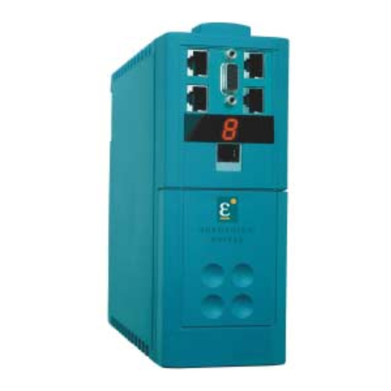
An Overview of the Servo Drive VERVIEW OF THE ERVO RIVE Component Identification X 3 0 X 1 5 / R S 2 3 2 Figure 2-1 View of Component Parts Main servo drive assembly Power terminal (X1) Product code label X15/RS232 Set-up service connection (EASYRIDER <) Terminal cover... -
Page 5: Control Features
An Overview of the Servo Drive Control Features CAN-Bus terminator CAN-Bus connection to next 631 controller (last controller is terminated) X 3 0 X 3 0 Encoder/Stepper connection to next 631 controller X 15/R S23 2 X15 /RS 23 2 Resolver Connection (mandatory) POWER... - Page 6 An Overview of the Servo Drive 631 Servo Drive Custom-made Software CAN-Bus current-loop X20/X21 speed-loop ° < RS232 EASYRIDER position-loop PLC I/O ±10V Instructions Diagnostics Setup Programming Figure 2-2 Communications Options Point-to-Point CAN-Bus Network Conventional Control Synchronisation (analog setpoint value) Position Control (electronic gearbox) Unit X...
-
Page 7: Understanding The Product Code
An Overview of the Servo Drive Understanding the Product Code The unit is fully identified using a five block alphanumeric code which records how the Servo Drive was calibrated, and its various settings when despatched from the factory. The Product Code appears as the “Model No.”. Each block of the Product Code is identified as below: Block Variable... - Page 8 Installing the Servo Drive NSTALLING THE ERVO RIVE IMPORTANT: Read Chapter 12: “Certification for the Servo Drive” before installing this unit. EMC Installation Hints All components are mounted on a mounting plate (minimum thickness 3mm) inside a steel cubicle. Ensure good grounding of the complete system, including the ground connections between the cubicle and machine.
-
Page 9: Mechanical Installation
Installing the Servo Drive Mechanical Installation Adjustable mounting clip can be easily re-positioned to allow different mounting configurations Fixing hole centres DIN mounting dimensions SIDE VIEW PANEL MOUNTING VIEW DIN MOUNTING VIEW Figure 3-1 Mechanical Dimensions for 631 631 Model Number 631 Model Number H H H H W W W W... -
Page 10: General Rule
Installing the Servo Drive Minimum Air Clearances Cubicle Size The digital servo drive is protected against damage caused by overheating. There is a thermal sensor installed on the heat sink. When the temperature rises to >95°C, the drive is automatically switched off. This setting cannot be changed. Use a cabinet of the correct size for adequate air circulation, see below. -
Page 11: Electrical Installation
Installing the Servo Drive Electrical Installation IMPORTANT: Please read the Safety Information on page Cont. 3 & 4 before proceeding. WARNING! Ensure that all wiring is electrically isolated and cannot be made “live” unintentionally by other personnel. All control/resolver/motor thermistor inputs, i.e protected by double insulation are SELV. -
Page 12: Motor Thermistor
Installing the Servo Drive Remove Terminal Cover by pressing here and pulling down Using Cage Clamp Terminals Remove the terminal cover as shown above. Insert a flat-bladed screwdriver (size 3.5 mm max.) inside the smallest hole. Lever the screwdriver, keeping it firmly pressed into the hole. The cage will open. - Page 13 Installing the Servo Drive When the ac supply is switched on, a pulse of current flows to earth to charge the internal/external ac supply EMC filter’s internal capacitors which are connected between phase and earth. This has been minimised in Eurotherm Drives’ filters, but may still trip out any circuit breaker in the earth system.
- Page 14 Installing the Servo Drive X1 - Motor and Power Wiring Connections 1 2 3 4 5 6 7 8 9 10 protective earth 230V ac 50/60Hz supply 230V ac 50/60Hz supply L2/N motor supply M1/U motor supply M2/V motor supply M3/W protective earth Motor Cable Clamp...
- Page 15 Installing the Servo Drive X10 - Control Wiring Connections Functional Earth connected to cubicle backplate providing clean earth for electronic ground and screens 1 2 3 4 5 6 7 8 9 10 Control Cable Retainer L2/N M1/U M2/V M3/W Screen Connections: ensure good connection with conductive surface...
- Page 16 Installing the Servo Drive Note: Use screened control cables to comply with EMC requirements. All control and signal terminals are SELV, i.e., protected by double/re-inforced insulation. Ensure all wiring is rated for the highest system voltage. Control wiring of between 0.08 mm (28 AWG) - 2.5 mm (14 AWG) can be used.
- Page 17 3-10 Installing the Servo Drive X30 - Resolver Connection IMPORTANT: Refer to the WARNING on page 3-5. The resolver provides a digital value for the rotor position to within one revolution, evaluation: 12 or 14 bit. It is adjustable in the Configuration Menu in the EASYRIDER software. •...
- Page 18 3-11 Installing the Servo Drive X40/41 - Multi-function Input/Output Connections This connection provides encoder emulation, encoder input and stepper motor interface. Note: Refer to Chapter 11: “Technical Specifications” - X40/X41 - Multi-function Input/Output. Incremental-Out Incremental-IN Incremental-IN MASTER SLAVE 1 SLAVE 2 mount units side-by-side if possible keep cables as short as possible X40/41 signals are referred to PE...
- Page 19 3-12 Installing the Servo Drive X40/41 Mode 0 - Incremental Output • Incremental encoder simulation for processing in positioning modules • Standard: 1024 increments; other selectable pulse numbers are 512, 256, 128 Encoder Emulation, Incremental OUT based on Resolver Incremental Encoder inputs or outputs conversion Function Function...
- Page 20 3-13 Installing the Servo Drive X40/41 Mode 1- Incremental Input Parameter area of the input signals is 10 - 1,000,000 increments Encoder IN Encoder Mode = 1 Incremental IN Incremental Encoder inputs or outputs Function Function Function Function 8-pole Modular Jack, EASYRIDER <...
- Page 21 3-14 Installing the Servo Drive X40/41 Mode 2 - Step-Control Pulse/Direction Pulse Stepper Motor Direction Control turn direction (+) turn direction (-) set-up time 2.5µs 2 hold time = 0 Steps in Pulse/Direction Mode = 2 Function Function Function Function 8-pole Modular Jack, 8-pole Modular Jack, EASYRIDER <...
- Page 22 3-15 Installing the Servo Drive X40/41 Mode 3 - Step-Control Pulse (+)(-) Stepper Motor pulse direction (+) Control pulse direction (-) Steps In Pulse (+) (-) Mode = 3 Function 8-pole Modular Jack, EASYRIDER < X40 mode = 3 8-pole Modular Jack, screened screened IN /P+...
- Page 23 3-16 Installing the Servo Drive X20/21 - CAN-Bus Digital Interface Connections Standard fieldbus protocol CAN-Bus interface. 124 Ohm CAN-Bus 124 Ohm Termination Termination LAST NODE NODE 1 NODE 2 To network several 631 servo drives, connect the X20/21 sockets as shown using the specified <...
-
Page 24: Control Philosophy
Operating Modes PERATING ODES Control Philosophy 631 servo drive 631 servo drive using a selection of all available functions: using: Resolver encoder CAN-Bus emulation Comms link RS232 RS232 multi-functional pulse interface (encoder, Resolver stepper etc.) analog analog input input digital i/o digital i/o Operating Modes Operating Modes... - Page 25 Operating Modes Configuring the OPTO Inputs and Outputs (X10) The OPTO Input and Output functions must be configured for use with each Operating Mode. The Input/Output functions for terminals X10.5, X10.6, X10.8, X10.9 and X10.10 are selected in the menu: “Commissioning/Input -Output”. The function of each input/output is determined by selecting a number from 0 to 5.
- Page 26 Operating Modes MODE 4 - POSITION CONTROL (POSITION BLOCKS) MODE 4 - POSITION CONTROL (POSITION BLOCKS) MODE 4 - POSITION CONTROL (POSITION BLOCKS) MODE 4 - POSITION CONTROL (POSITION BLOCKS) EASYRIDER EASYRIDER EASYRIDER EASYRIDER Description Description Description Description Termina Termina Termina Termina Function...
- Page 27 Operating Modes MODE 5 - POSITION CONTROL (BIAS PROGRAM) MODE 5 - POSITION CONTROL (BIAS PROGRAM) MODE 5 - POSITION CONTROL (BIAS PROGRAM) MODE 5 - POSITION CONTROL (BIAS PROGRAM) EASYRIDER EASYRIDER EASYRIDER EASYRIDER Description Description Description Description Termina Termina Function Function Termina...
- Page 28 Operating Modes Function Diagrams for Inputs/Outputs Fault signal / Protection mode switching off Protection mode limiting protection function in accordance with EASYRIDER config. menu in accordance with EASYRIDER config. menu regulator protection output Warning(F5) X10.6 output Ready(F0) X10.5 max. current Warning time approx.
-
Page 29: Motor Overload Protection
Operating Modes Motor Overload Protection This may be detected in two ways: Using Temperature Sensors These are located in the motor windings. Enter the relevant data (type, tripping value) in to the < EASYRIDER menu: COMMISSIONING / MOTOR / TEMPERATURE SENSOR. Internal Overlaod Protection Using thermal simulation of the motor in the drive (I²t), related to the rated current of the motor. -
Page 30: Initial Setup
Initial Set-up NITIAL Connecting the X15/RS232 EASYRIDER Set-up Service < < < < Connect your PC to the 631 Servo Drive using the supplied RS232 cable. The cable is wired as shown below. Refer to Chapter 9: “Accessories”. X15 RS232 X15 RS232 X15 RS232 X15 RS232... -
Page 31: Pre-Operation Checks
Initial Set-up Pre-Operation Checks WARNING! Wait for 5 minutes after disconnecting power before working on any part of the system or removing the terminal cover from the Servo Drive. Initial checks before applying power: • Mains power supply voltage is correct. •... -
Page 32: Commissioning Instructions
Initial Set-up Inital Set-up with EASYRIDER < < < < Note: Refer to your EASYRIDER software HELP menu. This chapter presumes you now have some experience of the EASYRIDER software. If not, we suggest you practice in Simulation Mode within EASYRIDER. Access to several software functions is password restricted. - Page 33 Initial Set-up Step Action Remark Tuning the Position Loop Switch the power OFF and de-couple Switch the power OFF and de-couple Switch the power OFF and de-couple Switch the power OFF and de-couple The first setup of the positioning loop should be executed with no load. (When the tuning is finished, the mechanics can be re-connected).
- Page 34 Initial Set-up Tuning the Current Loop IMPORTANT: Only undertake tuning the current loop after consulting with Eurotherm engineers. Stable parameters are calculated based on the system data and can be called up using the F5 key. Manual tuning may be necessary. Rated values can be sourced either digitally by the internal generator or analog by using ±10V at X10.1 and X10.2.
-
Page 35: Programming Your Application
Programming Your Application ROGRAMMING PPLICATION EASYRIDER Software The EASYRIDER software tool is provided to fine-tune the 631 servo drive to the motor, and program the servo drive for operation using either “Position Blocks” or the BIAS programming language. Install the software which is available as a DOS version, or suitable for use as a Windows application. - Page 36 Programming Your Application Set-up any other information necessary to your Operating Mode Select to save your changes to the drive Included with these pages are instructions on wiring, safety etc. The Speed Loop and Position Loop Optimization pages will already contain sensible values (loaded from your motor selection) and should require only fine tuning to your system.
- Page 37 Programming Your Application EASYRIDER Main Screen - Menu Options 631 Digital Servo Drive 07-01-08-02-E-V0500...
-
Page 38: Bias Commands
Programming Your Application BIAS Commands 07-01-08-02-E-V0500 631 Digital Servo Drive... - Page 39 Programming Your Application BIAS – Extended Command Overview These commands are only available with firmware version 5.13 onwards. With older firmware versions this command will cause the error message "invalid BIAS- command". General Keyboard Definitions terminate command activate menu system next parameter Shift+Tab previous parameter...
- Page 40 Programming Your Application BIAS Editor Keyboard Shortcuts Function Function Function Function General help screen for the BIAS Editor Shift+F1 Shift+F1 Shift+F1 Shift+F1 Help with the selected BIAS command Ctrl+F1 Ctrl+F1 Help with the actual BIAS block in program Ctrl+F1 Ctrl+F1 Load a BIAS program from disk Save the BIAS program to disk Transmit the BIAS program...
-
Page 41: Diagnostics And Fault Finding
Diagnostics and Fault Finding IAGNOSTICS AND AULT INDING The seven-segment display is illuminated when the servo drive is powered-up. It provides information on the state of the drive, active trips, and assists in fault finding. Remember to remove the protective film Diagnostic covering the display when installing the Display... - Page 42 Diagnostics and Fault Finding Display Display Display Display Explanation Explanation Explanation Explanation Ready * Ready * Ready * Ready * Warning * Warning * Warning * Warning * Comment Comment Comment Comment (output X10.5) (output X10.6) Supply undervoltage Is the power supply present? Status signal disappears, if DC-bus <Ua low threshold voltage over the threshold.
- Page 43 Diagnostics and Fault Finding Display Display Display Display Explanation Explanation Explanation Explanation Ready * Ready * Ready * Ready * Warning * Warning * Warning * Warning * Comment Comment Comment Comment (output X10.5) (output X10.6) overtemperature motor Check overload of the motor/cooling (NTC/PTC) etc.
-
Page 44: Drive Status
Diagnostics and Fault Finding Fault Finding The following list refers to faults which can occur during operation. Error Error Explanation and remedy Explanation and remedy Error Error Explanation and remedy Explanation and remedy * * * * Motor does not operate despite current flow Is the motor mechanically blocked? Is the motor brake released? Motor runs unevenly... - Page 45 Diagnostics and Fault Finding History Status Memory When the unit is powered down, a set of important indicators is stored in to dedicated memory. < This allows the last eight status conditions to displayed by the EASYRIDER diagnostic menu Thus important failure information, for instance, is not lost when the unit is powered down. 631 Digital Servo Drive 07-01-08-02-E-V0500...
-
Page 46: Routine Maintenance And Repair
Routine Maintenance and Repair OUTINE AINTENANCE AND EPAIR Routine Maintenance Periodically inspect the Servo drive for build-up of dust or obstructions that may affect ventilation of the unit. Remove this using dry air. Repair There are no user-serviceable components. IMPORTANT: MAKE NO ATTEMPT TO REPAIR THE UNIT - RETURN IT TO EUROTHERM DRIVES. Saving Your Application Data Although the Servo drive retains saved settings during power-down, it would be wise for you to keep a back-up of your data. - Page 47 Accessories CCESSORIES Note: Other cable lengths are available, contact Eurotherm Drives for details. Products Products Order Number Order Number Illustration Illustration Products Products Order Number Order Number Illustration Illustration Motor Cable Motor Cable Motor Cable Motor Cable CM469021U020 For ACG motors only Germany: Low-cost cable for fixed installations only MK.1042.0020...
- Page 48 Accessories Cable for Host Units Cable for Host Units Round cable, Cable for Host Units Cable for Host Units RJ45 Plug 8 way CM469033U010 4TP, shielded pairs X40/41 (Multi-function) Germany: 4 twisted pairs, shielded cable KK.6310.0401 unterminated at the free-end Adaptor Cable Adaptor Cable RJ45 Plug 8 way...
-
Page 49: Reference Tables
10-1 Reference Tables EFERENCE ABLES ASCII Table BINARY “ & ‘ < > 631 Digital Servo Drive 07-01-08-02-E-V0500... - Page 50 10-2 Reference Tables Decimal/Hexadecimal Table 0 0 0 0 1 1 1 1 2 2 2 2 3 3 3 3 4 4 4 4 5 5 5 5 6 6 6 6 7 7 7 7 8 8 8 8 9 9 9 9 0 0 0 0 0000...
- Page 51 10-3 Reference Tables Decimal/Hexadecimal Table 0 0 0 0 1 1 1 1 2 2 2 2 3 3 3 3 4 4 4 4 5 5 5 5 6 6 6 6 7 7 7 7 8 8 8 8 9 9 9 9 01F4 01F5...
-
Page 52: Technical Specifications
11-1 Technical Specifications ECHNICAL PECIFICATIONS General Data Environmental Details The unit MUST be mounted inside a suitable cubicle. Operating Temperature Operating Temperature Operating Temperature Operating Temperature 0°C to 40°C (derate the output current by 2% per °C between 40-50°C Operating temperature is defined as the ambient temperature to the immediate surround of the Servo Drive, when the Servo Drive and other equipment adjacent to it is operating at worst case conditions. -
Page 53: Cabling Requirements For Emc Compliance
11-2 Technical Specifications Cabling Requirements for EMC Compliance * For cable lengths longer than 15 and up to 50 metres contact Eurotherm Drives. Resolver Resolver Power Supply Power Supply Motor Cable Motor Cable Brake Resistor Brake Resistor Signal/Control Cable Signal/Control Cable Resolver Resolver Power Supply... -
Page 54: Earthing/Safety Details
11-3 Technical Specifications Earthing/Safety Details Refer to Chapter 12 : “Certification for the Servo Drive”. Earthing Earthing Permanent earthing is mandatory on all units. Earthing Earthing • Use a copper protective earth conductor 10mm² minimum cross-section, or install a second conductor in parallel with the protective conductor to a separate protective earth terminal •... -
Page 55: Controller System
11-4 Technical Specifications Resolver Conversion (X30) The specified data refers to the standard resolver interface, operated with the Eurotherm Resolver R 21-T05, R15-T05. Carrier frequency Carrier frequency Carrier frequency Carrier frequency f t = 4.75kHz Linearity error of the actual value Linearity error of the actual value Linearity error of the actual value Linearity error of the actual value... -
Page 56: Digital Control
11-5 Technical Specifications Digital Control Current Control Current Control Current Control Current Control Settings Settings Settings Settings According to factory specifications or motor data Current Limits Current Limits Set by the Parameter Menu Current Limits Current Limits Speed Control Speed Control Speed Control Speed Control Settings... -
Page 57: Product Specific Data
11-6 Technical Specifications Product Specific Data IMPORTANT: Motor power, output current and input current must not be exceeded under steady state operating conditions. 631 Product Code - block 2 631 Product Code - block 2 631 Product Code - block 2 631 Product Code - block 2 EMC Compliance European Community Directive 89/336/EEC... -
Page 58: Requirements For Emc Compliance
12-1 Certification for the Servo Drive ERTIFICATION FOR THE ERVO RIVE Requirements for EMC Compliance All Variable Speed Drives (VSDs) potentially produce electrical emissions which are radiated into the environment and conducted back into the ac supply. VSDs are inherently immune to any additional external electrical noise. -
Page 59: Cabling Requirements
12-2 Certification for the Servo Drive Control and signal cables for the encoder and all analog inputs normally require screening with the screen connected only at the VSD end. However, if high frequency noise is still a problem, earth screen at the non VSD end via a 0.1µF capacitor. Note: Connect the screen (at the VSD end) to the VSD protective earth point, and not to the control board terminals. -
Page 60: Screening & Earthing (Cubicle Mounted, Class B)
12-3 Certification for the Servo Drive Note: The installation requirements of local safety standards must be achieved regarding the safety of electrical equipment for machines. • A single-star point earthing policy as shown in Fehler! Verweisquelle konnte nicht gefunden werden. is required. •... -
Page 61: Star Point Earthing
12-4 Certification for the Servo Drive Star Point Earthing U-clip used to terminate screen to motor to motor to motor connection to the back panel screened screened Back Panel Metal Work Earth Doors Back Metal Panel Work 24V Control Digital Clean Earth Analogue Clean Earth unscreened signals Dirty Earth... -
Page 62: Sensitive Equipment
12-5 Certification for the Servo Drive Sensitive Equipment The proximity of the source and victim circuit has a large effect on radiated coupling. The electromagnetic fields produced by VSDs falls off rapidly with distance from the cabling/cubicle. Remember that the radiated fields from EMC compliant drive systems are measured at least 10m from the equipment, over the band 30-1000MHz. -
Page 63: Requirements For Ul Compliance
12-6 Certification for the Servo Drive Requirements for UL Compliance Solid-State Motor Overload Protection These devices provide Class 10 motor overload protection. The maximum internal overload protection level (current limit) is 200% for 9 seconds. An external motor overload protective device must be provided by the installer where the motor has a full-load ampere rating of less than 50% of the drive output rating. -
Page 64: European Directives And The Ce Mark
12-7 Certification for the Servo Drive European Directives and the CE Mark The following information is supplied to provide a basic understanding of the EMC and low voltage directives CE marking requirements. The following literature is recommended for further information: •... -
Page 65: Customer Responsibility
12-8 Certification for the Servo Drive Eurotherm Drives Responsibility You intend to use the unit as relevant apparatus. When the unit is factory-fitted with the internal EMC filter and installed following EMC installation instructions, it complies with the relevant standards indicated in the following tables. The relevant declarations are to be found at the end of this chapter. - Page 66 12-9 Certification for the Servo Drive Conformance can be demonstrated using the Generic Standards or the Product Specific Standard. The following tables indicate, for the two methods of compliance, the standards that the unit may comply with if installed and used correctly. Unit used as Unit used as Unit used as...
- Page 67 12-10 Certification for the Servo Drive IEC1000-4-2 Electrostatic discharge (e.g. from electrostatically IEC1000-4-4: Fast electrical transients (burst) (e.g. from charged persons) opening contacts in inductive circuits) IEC1000-4-3 Electromagnetic fields (e.g. from portable IEC1000-4-5: Voltage surges (e.g. on local lightning strikes) telephones) ENV50140: Pulse Modulated Electromagnetic Field...
- Page 68 12-11 Certification for the Servo Drive Unit used as Unit used as Unit used as Unit used as Unit used as a Unit used as a Unit used as a Unit used as a Product Specific Standard EN61800-3 Relevant Apparatus Relevant Apparatus Relevant Apparatus Relevant Apparatus...
- Page 69 12-12 Certification for the Servo Drive START IS E.D. MODULE RELEVANT APPARATUS WITH INTRINSIC FUNCTION TO END USER (CEMEP VALIDITY FIELD 1) CEMEP VALIDITY FIELDS 2, 3 AND 4 WILL THE E.D. PRODUCT BE INSTALLED ACCORDING TO THE INSTALLATION EMC CHARACTERISTICS GUIDELINES STATED IN MANUAL FITTED WITH THE...
- Page 70 12-13 Certification for the Servo Drive Certificates EC D ECLARATIONS OF ONFORMITY Date CE marked first applied: 07/04/99 EMC Directive Low Voltage Directive Issued for The drive is CE compliance In accordance with the EEC Directive marked in In accordance with the EEC Directive 73/23/EEC and amended by 93/68/EEC, with the EMC accordance with...
-
Page 71: Application Notes
13-1 Application Notes PPLICATION OTES Application advice is available through our Technical Support Department, who can also arrange for on-site assistance if required. Refer to Chapter 8: “Routine Maintenance and Repair” for the address of your local Eurotherm Drives company. •... -
Page 72: Dynamic Braking
13-2 Application Notes Dynamic Braking The energy of a moving system flows back into the drive while decelerating. The DC-Bus capacitors are able to take a small value. The remainder is converted to heat by a high power resistor switched across the DC link. Switching on and off of this brake resistor depends on the DC-Bus voltage. - Page 73 13-3 Application Notes STEP 2: To determine if a brake resistor is required Example Calculation Drive model 631/004 selected Do you require an external brake-resistor? Drive Data from Chapter 11 Drive Data from Chapter 11 Drive Data from Chapter 11 Drive Data from Chapter 11 In case of insufficient capability of the internal brake resistor, an external...
- Page 74 13-4 Application Notes Approximate calculation of required motor terminal voltage for a specified motor speed (up to 3000rpm) Ukl = 1,2 (EMC*n/1000 + I* (Rph + RL) (Volts) where: Required motor voltage (V rms) Back-EMF of motor (V rms)/1000 rpm Resistance of motor (between terminals) (Ω) Line resistance of motor cable (Ω) Motor-current (A rms)
-
Page 75: Functional Block Diagram
14-1 Functional Block Diagram UNCTIONAL LOCK IAGRAM Current Limit Configurable Functions (Limit Switches etc.) Supervising Setpoint Processing Speed+ Speed- Speed Loop Nsoll A/D Converter Analog Input Nsoll Speed Demand IQsoll Current Demand SELV Isolation IQsoll Current Demand VDE 0884 VDE 0160 / EN50178 MOTOR Current Loop IGBT... - Page 76 Modification Record Version Modification Chapter Date Name shorthand Comment expression Preliminary V1 initial 02.10.98 V02.47PL98 überarbeitet 16.11.98 V03.16PL99 überarbeitet alle / all 22.04.99 PL/GV/ST V04.21PL99 neues Thema für 25.05.99 PL/ST Kapitel 3 neues Kapitel Textänderung neue BIAS-Befehle 12.5 neues Kapitel 12.6 V0500 German Layout...
Need help?
Do you have a question about the 631 series and is the answer not in the manual?
Questions and answers