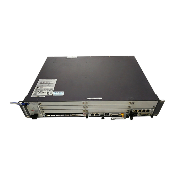
Huawei BBU3900 Hardware Maintenance Manual
Hide thumbs
Also See for BBU3900:
- Hardware description (104 pages) ,
- Installation manual (58 pages) ,
- Description (29 pages)

Related Manuals for Huawei BBU3900


Summary of Contents for Huawei BBU3900
- Page 1 BBU3900 V200 Hardware Maintenance Guide Issue Date 2010-06-05 HUAWEI TECHNOLOGIES CO., LTD.
- Page 3 All other trademarks and trade names mentioned in this document are the property of their respective holders. Notice The purchased products, services and features are stipulated by the contract made between Huawei and the customer. All or part of the products, services and features described in this document may not be within the purchase scope or the usage scope.
-
Page 5: About This Document
About This Document Introduction This document describes the routine hardware maintenance of the BBU3900. The maintenance tasks consist of power supply and grounding system maintenance, cabinet maintenance, and power-on and power-off operations. This document also describes the procedures for replacing the components. - Page 6 This describes how to power on and power off the BBU3900. During power-on, you need to check the status of the LEDs on the BBU3900. As for the power-off, the operation in a normal situation and that in an emergency are different.
- Page 7 Multi-level menus are in boldface and separated by the ">" signs. For example, choose File > Create > Folder. Keyboard Operations The keyboard operations that may be found in this document are defined as follows. Issue 03 (2010-06-05) Huawei Proprietary and Confidential Copyright © Huawei Technologies Co., Ltd.
- Page 8 Press the primary mouse button twice continuously and quickly without moving the pointer. Drag Press and hold the primary mouse button and move the pointer to a certain position. Huawei Proprietary and Confidential Issue 03 (2010-06-05) Copyright © Huawei Technologies Co., Ltd.
-
Page 9: Table Of Contents
BBU3900 Hardware Maintenance Guide Contents Contents About This Document........................iii 1 Changes in the BBU3900 Hardware Maintenance Guide..........1-1 2 Maintenance Items for the BBU3900 Equipment..............2-1 3 Powering On/Off the BBU3900....................3-1 3.1 Powering On the BBU.............................3-2 3.2 Powering Off the BBU............................3-3 4 Replacing the Components in the OMB................4-1 4.1 Replacing the HEUA............................4-2... - Page 11 Figure 5-11 Removing the UEIU........................5-10 Figure 5-12 Position of the FAN unit.........................5-11 Figure 5-13 Removing the FAN unit.........................5-12 Figure 5-14 Position of the USCU........................5-14 Figure 5-15 Disconnecting cables........................5-14 Issue 03 (2010-06-05) Huawei Proprietary and Confidential Copyright © Huawei Technologies Co., Ltd.
- Page 12 Figure 5-18 Disconnecting the cable........................5-16 Figure 5-19 Removing the WBBP........................5-17 Figure 5-20 Position of the optical module......................5-18 Figure 5-21 Disconnecting cables........................5-19 Figure 5-22 Removing the optical module......................5-19 Huawei Proprietary and Confidential Issue 03 (2010-06-05) Copyright © Huawei Technologies Co., Ltd.
- Page 13 BBU3900 Hardware Maintenance Guide Tables Tables Table 2-1 Maintenance items for the BBU3900 equipment ................2-1 Issue 03 (2010-06-05) Huawei Proprietary and Confidential Copyright © Huawei Technologies Co., Ltd.
-
Page 15: Changes In The Bbu3900 Hardware Maintenance Guide
1 Changes in the BBU3900 Hardware Maintenance Guide Changes in the BBU3900 Hardware Maintenance Guide This describes the changes in the BBU3900 Hardware Maintenance Guide 03 (2010-06-05) This is the second commercial release. Compared with issue 02 (2010-03-05), no information is added. - Page 16 BBU3900 1 Changes in the BBU3900 Hardware Maintenance Guide Hardware Maintenance Guide 01 (2008-12-30) This is the initial field trial release. Huawei Proprietary and Confidential Issue 03 (2010-06-05) Copyright © Huawei Technologies Co., Ltd.
-
Page 17: Maintenance Items For The Bbu3900 Equipment
2 Maintenance Items for the BBU3900 Equipment Maintenance Items for the BBU3900 Equipment This describes the maintenance items for the BBU3900 equipment. The maintenance items are related to the fans, equipment surface, cleanliness, LEDs, and ambient temperature in the cabinet. Table 2-1 describes the maintenance items for the BBU3900 equipment. -
Page 19: Powering On/Off The Bbu3900
This describes how to power on and power off the BBU3900. During power-on, you need to check the status of the LEDs on the BBU3900. As for the power-off, the operation in a normal situation and that in an emergency are different. -
Page 20: Powering On The Bbu
BBU3900 3 Powering On/Off the BBU3900 Hardware Maintenance Guide 3.1 Powering On the BBU Before powering on the BBU, set the power switch on the BBU to ON and determine the operation status of the BBU based on the status of the LEDs. -
Page 21: Powering Off The Bbu
BBU3900 Hardware Maintenance Guide 3 Powering On/Off the BBU3900 3.2 Powering Off the BBU The BBU power-off is classified into normal power-off and emergency power-off. Procedure Step 1 Choose normal power-off or emergency power-off based on the actual situation. If... -
Page 23: Replacing The Components In The Omb
4.4 Replacing the AC Surge Protection Box The AC surge protection box provides protection for the AC input power. Issue 03 (2010-06-05) Huawei Proprietary and Confidential Copyright © Huawei Technologies Co., Ltd. -
Page 24: Replacing The Heua
HEUA in the OMB. Figure 4-1 Position of the HEUA HEUA Procedure Step 1 Wear an ESD wrist strap or a pair of ESD gloves. Huawei Proprietary and Confidential Issue 03 (2010-06-05) Copyright © Huawei Technologies Co., Ltd. -
Page 25: Figure 4-2 Disconnecting Cables
Fill in the fault form with the details of the replaced component. Contact the local Huawei office to handle the faulty component. Issue 03 (2010-06-05) Huawei Proprietary and Confidential Copyright ©... -
Page 26: Replacing The Ac/Dc Power Equipment
Figure 4-4 Position of the AC/DC power equipment in the cabinet (1) AC/DC power equipment Figure 4-5 shows the positions of the components in the AC/DC power equipment. Huawei Proprietary and Confidential Issue 03 (2010-06-05) Copyright © Huawei Technologies Co., Ltd. -
Page 27: Figure 4-5 Positions Of The Components In The Ac/Dc Power Equipment
Step 4 Disconnect the cables. Disconnect the DC output power cable from the PDU, as shown in Figure 4-6. Figure 4-6 Disconnecting the cable from the PDU Issue 03 (2010-06-05) Huawei Proprietary and Confidential Copyright © Huawei Technologies Co., Ltd. -
Page 28: Figure 4-7 Disconnecting The Cable From The Pmu
Step 5 Remove the component to be replaced. Loosen the M3 screw on the panel of the PDU, and then remove the PDU, as shown in Figure 4-9. Huawei Proprietary and Confidential Issue 03 (2010-06-05) Copyright © Huawei Technologies Co., Ltd. -
Page 29: Figure 4-9 Removing The Pdu
Figure 4-10. Figure 4-10 Removing the PSU Loosen the M3 screw on the panel of the PMU, and then remove the PMU, as shown in Figure 4-11. Issue 03 (2010-06-05) Huawei Proprietary and Confidential Copyright © Huawei Technologies Co., Ltd. -
Page 30: Figure 4-11 Removing The Pmu
Loosen the four M6 screws on the mounting ears of the subrack, and then remove the subrack, as shown in Figure 4-12. Figure 4-12 Removing the subrack Huawei Proprietary and Confidential Issue 03 (2010-06-05) Copyright © Huawei Technologies Co., Ltd. -
Page 31: Replacing The Dcdu-03B
Fill in the fault form with the details of the replaced component. Contact the local Huawei office to handle the faulty component. 4.3 Replacing the DCDU-03B The DCDU-03B distributes DC power to different components. -
Page 32: Figure 4-13 Position Of The Dcdu-03B
Step 3 Record all the cable connections on the panel of the board to be replaced. Step 4 Disconnect the power cables from the DCDU-03B, as shown in Figure 4-14. 4-10 Huawei Proprietary and Confidential Issue 03 (2010-06-05) Copyright © Huawei Technologies Co., Ltd. -
Page 33: Figure 4-14 Disconnecting Cables
Figure 4-14 Disconnecting cables Step 5 Loosen the four M6 screws on the panel, and then remove the DCDU-03B, as shown in Figure 4-15. Figure 4-15 Removing the DCDU-03B Issue 03 (2010-06-05) Huawei Proprietary and Confidential 4-11 Copyright © Huawei Technologies Co., Ltd. -
Page 34: Replacing The Ac Surge Protection Box
Fill in the fault form with the details of the replaced component. Contact the local Huawei office to handle the faulty component. 4.4 Replacing the AC Surge Protection Box The AC surge protection box provides protection for the AC input power. -
Page 35: Figure 4-16 Position Of The Ac Surge Protection Box
Step 3 Record all the cable connections on the panel of the AC surge protection box to be replaced. Step 4 Disconnect the power cable and monitoring cable from the AC surge protection box, as shown Figure 4-17. Issue 03 (2010-06-05) Huawei Proprietary and Confidential 4-13 Copyright © Huawei Technologies Co., Ltd. -
Page 36: Figure 4-17 Disconnecting Cables
1.2 N·m, and then reconnect the cables. Step 7 Power on the base station. Step 8 Take off the ESD wrist strap or gloves, and then pack up all the tools. ----End 4-14 Huawei Proprietary and Confidential Issue 03 (2010-06-05) Copyright © Huawei Technologies Co., Ltd. - Page 37 Fill in the fault form with the details of the replaced component. Contact the local Huawei office to handle the faulty component. Issue 03 (2010-06-05)
-
Page 39: Replacing Components Of The Bbu3900
BBU3900 Hardware Maintenance Guide 5 Replacing Components of the BBU3900 Replacing Components of the BBU3900 About This Chapter This describes how to replace components of the BBU. The components are the BBU case, boards and module of the BBU, and optical modules. - Page 40 BBU3900 5 Replacing Components of the BBU3900 Hardware Maintenance Guide 5.9 Replacing the WBBP The WCDMA Baseband Process Unit (WBBP) configured in the BBU processes baseband signals. 5.10 Replacing the Optical Module The optical module implements optical-electrical conversion, thus enabling optical transmission between the BBU and other devices.
-
Page 41: Querying Board Information
BBU3900 Hardware Maintenance Guide 5 Replacing Components of the BBU3900 5.1 Querying Board Information Before replacing a board, you need to query the board information at the remote end to confirm the type of board to be replaced. Run the LST BRDINFO command on the LMT. -
Page 42: Figure 5-2 Removing The Bbu
BBU3900 5 Replacing Components of the BBU3900 Hardware Maintenance Guide Step 2 Power off the BBU. For details, see 3.2 Powering Off the BBU. Step 3 Wear an ESD wrist strap or a pair of ESD gloves. WARNING Take proper ESD protection measures, for example, wear an ESD wrist strap or a pair of ESD gloves, to prevent electrostatic damage to the boards, modules, or electronic components. -
Page 43: Replacing The Wmpt
Fill in the fault form with the details of the replaced component. Contact the local Huawei office to handle the faulty component. 5.3 Replacing the WMPT The WCDMA Main Processing &... -
Page 44: Figure 5-4 Disconnecting Cables
BBU3900 5 Replacing Components of the BBU3900 Hardware Maintenance Guide WARNING Take proper ESD protection measures, for example, wear an ESD wrist strap or a pair of ESD gloves, to prevent electrostatic damage to the boards, modules, or electronic components. -
Page 45: Replacing The Upeu
Fill in the fault form with the details of the replaced board. Contact the local Huawei office to handle the faulty board. 5.4 Replacing the UPEU This describes the Universal Power and Environment Interface Unit (UPEU) board. -
Page 46: Figure 5-7 Disconnecting Cables
Replacing the UPEU disrupts all the services carried by the base station if no standby UPEU is configured. Step 2 Power off the BBU. For details, see Powering Off the BBU3900. Step 3 Wear an ESD wrist strap or a pair of ESD gloves. -
Page 47: Replacing The Ueiu
Fill in the fault form with the details of the replaced board. Contact the local Huawei office to handle the faulty board. 5.5 Replacing the UEIU The Universal Environment Interface Unit (UEIU) provides channels for transmitting the monitoring signals from the service board to the BBU. -
Page 48: Figure 5-10 Disconnecting Cables
BBU3900 5 Replacing Components of the BBU3900 Hardware Maintenance Guide Procedure Step 1 Wear an ESD wrist strap or a pair of ESD gloves. WARNING Take proper ESD protection measures, for example, wear an ESD wrist strap or a pair of ESD gloves, to prevent electrostatic damage to the boards, modules, or electronic components. -
Page 49: Replacing The Fan Unit
Fill in the fault form with the details of the replaced component. Contact the local Huawei office to handle the faulty component. 5.6 Replacing the FAN Unit The FAN unit is located in the BBU. -
Page 50: Replacing The Utrp
Fill in the fault form with the details of the replaced component. Contact the local Huawei office to handle the faulty component. 5.7 Replacing the UTRP The Universal Transmission Processing unit (UTRP) is the BBU transmission extension board. -
Page 51: Replacing The Uscu
----End Postrequisite Record the bar code of the replaced board. Contact the local Huawei office to handle the faulty UTRP. 5.8 Replacing the USCU The Universal Satellite card and Clock Unit (USCU) in the BBU receives clock signals such as the GPS, RGPS, BITS, and M-1PPS signals. -
Page 52: Figure 5-14 Position Of The Uscu
BBU3900 5 Replacing Components of the BBU3900 Hardware Maintenance Guide Prerequisite The tools and materials, such as an ESD wrist strap or ESD gloves and screwdriver, are ready. The quantity and type of board to be replaced are confirmed. For details, see 5.1 Querying... -
Page 53: Replacing The Wbbp
Fill in the fault form with the details of the replaced component. Contact the local Huawei office to handle the faulty component. 5.9 Replacing the WBBP The WCDMA Baseband Process Unit (WBBP) configured in the BBU processes baseband signals. -
Page 54: Figure 5-17 Position Of The Wbbp
BBU3900 5 Replacing Components of the BBU3900 Hardware Maintenance Guide Context Figure 5-17 shows the position of the WBBP in the BBU. Figure 5-17 Position of the WBBP RX TX WBBP CPRI0/EIH0 CPRI1/EIH1 CPRI2/EIH2 WBBP The WBBP is hot-swappable. Procedure... -
Page 55: Replacing The Optical Module
Fill in the fault form with the details of the replaced component. Contact the local Huawei office to handle the faulty component. 5.10 Replacing the Optical Module The optical module implements optical-electrical conversion, thus enabling optical transmission between the BBU and other devices. -
Page 56: Figure 5-20 Position Of The Optical Module
BBU3900 5 Replacing Components of the BBU3900 Hardware Maintenance Guide Context Figure 5-20 shows the position of the optical module on a board. Figure 5-20 Position of the optical module (1) Optical module The optical module is hot-swappable. Procedure Step 1 Wear an ESD wrist strap or a pair of ESD gloves. -
Page 57: Figure 5-21 Disconnecting Cables
BBU3900 Hardware Maintenance Guide 5 Replacing Components of the BBU3900 Figure 5-21 Disconnecting cables WARNING Do not look into the optical module without eye protection after the optical cable is removed from the optical module. Step 5 Turn the puller on the faulty optical module outwards, hold the puller and take the faulty optical... - Page 58 Fill in the fault form with the details of the replaced component. Contact the local Huawei office to handle the faulty component. 5-20 Huawei Proprietary and Confidential Issue 03 (2010-06-05) Copyright ©...
Need help?
Do you have a question about the BBU3900 and is the answer not in the manual?
Questions and answers