
Related Manuals for Hawking HW9ACM


Summary of Contents for Hawking HW9ACM
- Page 1 Wireless-1200AC Multifunction AP/BRIDGE/REPEATER HW9ACM website www.hawkingtech.com USER’S MANUAL e-mail techsupport@hawkingtech.com © COPYRIGHT 2015 HAWKING TECHNOLOGIES,INC. ALL RIGHTS RESERVED.
- Page 2 "as is". Should the programs prove defective following their purchase, the buyer (and not Hawking Technologies, its distributor, or its dealer) assumes the entire cost of all necessary servicing, repair, and any incidental or consequential damages resulting from any defect in the software.
- Page 3 Federal Communication Commission Interference Statement FCC Part 15 This equipment has been tested and found to comply with the limits for a Class B digital device, pursuant to Part 15 of FCC Rules. These limits are designed to provide reasonable protection against harmful interference in a residential installation.
- Page 4 Any changes or modifications not expressly approved by the party responsible for compliance could void the authority to operate equipment. Federal Communication Commission (FCC) Radiation Exposure Statement This equipment complies with FCC radiation exposure set forth for an uncontrolled environment. In order to avoid the possibility of exceeding the FCC radio frequency exposure limits, human proximity to the antenna shall not be less than 20cm (8 inches) during normal operation.
- Page 5 R&TTE Compliance Statement This equipment complies with all the requirements of DIRECTIVE 1999/5/EC OF THE EUROPEAN PARLIAMENT AND THE COUNCIL of March 9, 1999 on radio equipment and telecommunication terminal Equipment and the mutual recognition of their conformity (R&TTE). The R&TTE Directive repeals and replaces in the directive 98/13/EEC (Telecommunications Terminal Equipment and Satellite Earth Station Equipment) As of April 8, 2000.
-
Page 6: Table Of Contents
Chapter II: Quick Setup and Basic Settings ..........8 2-1 Installing the HW12ACM ..................8 2-2 Connecting to the HW9ACM by Web Browser ........... 9 2-2-1 Windows 95/98/Me IP Address Setup: ............10 2-2-2 Windows 2000 IP Address Setup ..............12 2-2-3 Windows XP IP Address Setup ............... - Page 7 3-5-1 Local Network ....................79 3-5-2 DHCP Server ....................80 3-5-3 Static DHCP Leases Table ................81 3-6 Wireless Network ....................83 3-6-1 Basic Wireless Settings ................... 84 3-6-1-1 Access Point ..................... 84 3-6-1-2 Bridge (Station Infrastructure) ..............89 3-6-1-3 AP Bridge-Point to Point ................90 3-6-1-4 AP Bridge-Point to Multi-Point ...............
- Page 8 3-9-4 Demilitarized Zone (DMZ) ................150 Chapter IV Status and Tools ..............153 4-1 System Status ....................153 4-1-1 System information and firmware version ........... 153 4-1-2 Internet Connection Status ................153 4-1-3 Local Network ....................154 4-1-4 System Log ....................156 4-1-5 Security Log ....................
-
Page 9: Chapter I: Product Information
Chapter I: Product Information 1-1 Product Introduction Thank you for purchasing the Hawking HW9ACM Wireless-1200AC Multifunction AP/Bridge/Repeater Easy installation procedures allow any computer user to setup a network in very short time - within minutes, even inexperienced users. Just follow the instructions given in this... -
Page 10: Safety Information
3. DO NOT pull any connected cable with force; disconnect it from the HW9ACM first. 4. If you want to place this HW9ACM at high places or hang on the wall, please make sure the HW9ACM is firmly secured. Falling from high places would damage the HW9ACM and its accessories, and void the warranty. -
Page 11: System Requirements
1-3 System Requirements Computer or network device(s) with wired or wireless network interface card. Web browser (Microsoft Internet Explorer 4.0 or above, Netscape Navigator 4.7 or above, Opera web browser, Mozilla Firefox web browser or Safari web browser). ... -
Page 12: Package Contents
1-4 Package Contents Before you start to use this HW9ACM, please check if there is anything missing in the package. Contact your place of purchase to claim missing items: 1x – HW9ACM Wireless-1200AC Multifunction AP/Bridge/Repeater 1x - Quick Installation Guide... -
Page 13: Product Overview
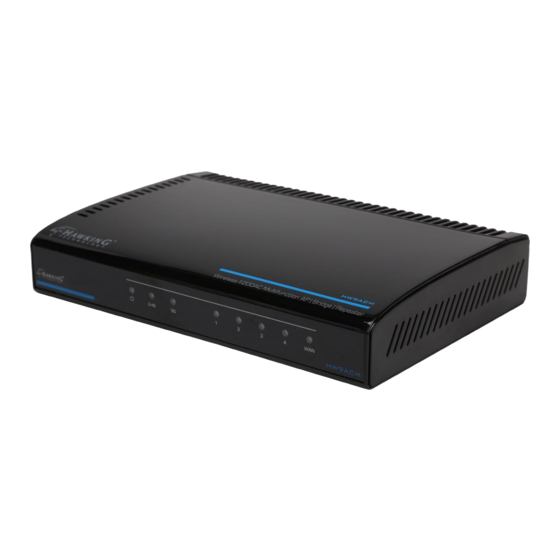
1-5 Product Overview Top Panel LED Name Light Status Description Router is switched on and correctly powered. 2.4GHz Wireless WPS function is enabled. 2.4GHz Wireless network is switched off. 2.4G Flashing 2.4GHz Wireless LAN activity (transferring or receiving data). 5GHz Wireless WPS function is enabled. 5GHz Wireless network is switched off. - Page 14 function. 1 – 4 Local Area Network (LAN) ports 1 to 4. Wide Area Network (WAN / Internet) port. Power Jack Power connector, connects to 12V/1A power adapter.
-
Page 15: Chapter Ii: Quick Setup And Basic Settings
HW9ACM by Ethernet cable or connect to it wirelessly. 3. Please check all LEDs on the front panel. LAN LEDs should be on if the HW9ACM is correctly connected. If it is not on, or any LED you expect is not on, please recheck... -
Page 16: Connecting To The Hw9Acm By Web Browser
2-2 Connecting to the HW9ACM by Web Browser After your HW9ACM Hi-Gain™ Wireless-AC Multi-Function Access Point / Bridge has been connected and powered the next step is to access the Web Menu for initial configuration. To do this, your computer must be able to get an IP address automatically (use dynamic IP address setting). -
Page 17: Windows 95/98/Me Ip Address Setup
2-2-1 Windows 95/98/Me IP Address Setup: 1. Click ‘Start’ button (it should be located at lower-left corner of your computer), then click control panel. Double-click Network icon, and Network window will appear. Select ‘TCP/IP’, then click ‘Properties’. 2. Select ‘Obtain an IP address from a DHCP server’ and then click ‘OK’. -
Page 19: Windows 2000 Ip Address Setup
2-2-2 Windows 2000 IP Address Setup 1. Click ‘Start’ button (it should be located at lower-left corner of your computer), then click control panel. Double-click Network and Dial-up Connections icon; click Local Area Connection, and Local Area Connection Properties window will appear. Select ‘Internet Protocol (TCP/IP)’... -
Page 21: Windows Xp Ip Address Setup
2-2-3 Windows XP IP Address Setup 1. Click ‘Start’ button (it should be located at lower-left corner of your computer), then click control panel. Double-click Network and Internet Connections icon, click Network Connections, and then double-click Local Area Connection, Local Area Connection Status window will appear, and then click ‘Properties’... -
Page 23: Windows Vista/7/8 Ip Address Setup
2-2-4 Windows Vista/7/8 IP Address Setup 1. Click ‘Start’ button (it should be located at lower-left corner of your computer), then click control panel. Under Network and Internet, Click View Network Status and Tasks, then click Manage Network Connections/Change Adapter Settings on the right hand column. -
Page 25: Mac Os X Ip Address Setup
2-2-5 Mac OS X IP Address Setup Go to your system preferences, go to network. Select your network connection. Make sure ‘Configure’ is set to ‘Using DHCP’. -
Page 26: Tablet/Smartphone Setup
2-2-6 Tablet/Smartphone Setup iOS (iPhone or iPad) Go to your settings on your tablet or smart phone First, make sure JavaScript is On: Go to Settings icon Select Safari > make sure JavaScript is ON. Go back to Home Screen, Select Settings In Wi-Fi Networks, select “Hawking_HW9ACM…”... - Page 27 Look for Hawking_HW9ACM…, then select to connect...
-
Page 28: Connecting To Web Management Interface
2-2-7 Connecting to Web Management Interface All functions and settings of this HW9ACM can be configured via web management interface. Please start your web browser, and input ‘192.168.1.230’ in address bar, then press the ‘Enter’ key. The following message should be shown: Please input user name and password in the fields respectively, default user name is ‘admin’, and default password is ‘1234’, then press the ‘OK’... - Page 29 NOTE: If you can’t see the web management interface, and you are being prompted to input the user name and password again, it means you didn’t input the username and password correctly. Retype the user name and password again. If you’re certain about the username and password you typed are correct, please go to ‘5-2 Troubleshooting’...
-
Page 30: Quick Setup
2-3 ‘Quick Setup’ This HW9ACM provides a ‘Quick Setup’ procedure, which will help you to complete all required settings you need to access the Internet in very short time. Please follow the following instructions to complete the ‘Quick Setup’: Please go to Quick Setup Wizard menu by clicking ‘Quick Setup’ button. - Page 31 On this page, please select the mode you wish to use. There are 6 modes that the HW9ACM supports: Repeater - Please go to section 2-3-1 Router - Please go to section 2-3-2 Access Point - Please go to section 2-3-3...
-
Page 32: Setup Procedure For 'Repeater
2-3-1 Setup Procedure for ‘Repeater’ Step 1) Choose Extender Mode. - Page 33 Step 2) The HW9ACM will first scan for available 2.4GHz networks. If you do not see anything, you can click ‘Scan’. If you do not want to use 2.4GHz, you can click “skip” and it will bypass the 2.4GHz network.
- Page 34 By default, the HW9ACM will use the same wireless name as your original WiFi network. You can uncheck the box to make changes if you wish. If you wish to give the HW9ACM an IP address, uncheck the input box and type in your own IP and subnet mask...
- Page 35 Step 6) Congratulations! You have completed the setup of the HW9ACM. Click Finish for the device to reboot.
-
Page 36: Setup Procedure For 'Router
2-3-2 Setup Procedure for ‘Router’... - Page 37 Step 1) Choose Router Mode. Step 2) Choose your Time Zone. This is used for system and security logs. Click ‘Next’...
- Page 38 Step 3) On this page, choose your Internet Service Provider Type. Most users use “Dynamic IP”. If you use the other modes, please make sure you have your Internet Provider’s supplied information to input your Static IP or user accounts for PPPoE...
- Page 39 For Dynamic, you may need to input a Host Name and/or Clone Mac Address. Most users do not need to do these steps. If you use static or PPPoE, please refer to section 3-4-2 and 3-4-3 Click ‘Next’, otherwise, input the information as provided by your ISP. Step 4) Input the Wireless Settings you wish to use in Router Mode.
- Page 40 not see the 5GHz signal. To add wireless security for your local/home wireless network, enter an alphanumerical password (8 characters or more) below (If you do not wish to use a password, leave the field blank and click 'Next'). Users signing on to your home wireless network will be required to enter this password to connect to the internet.
-
Page 41: Setup Procedure For 'Access Point
2-3-3 Setup Procedure for ‘Access Point’ Step 1) Choose Access Point Mode. Step 2) Choose your settings... - Page 42 Wireless (1): Shows you if the wireless is enabled/disabled ESSID (2): The HW9ACM transmits in both 2.4GHz and 5GHz WiFi frequencies. Please input the ESSID (the name used to identify this wireless access point) for each frequency here. You can input up to 32 alphanumerical characters.
- Page 43 2.4GHz Band If you select 2.4GHz (B), 2.4GHz (N), or 2.4GHz (G), only wireless clients using the wireless band you select (802.11b, 802.11 Draft-N, or 802.11g) will be able to connect to this access point. If you select 2.4GHz (B+G), then only wireless clients using 802.11b and 802.11g band will be able to connect to this access point.
- Page 44 5GHz (A+N+AC): this mode allows 802.11a, 802.11n and 802.11ac wireless network client to connect this router (maximum transfer rate 54Mbps for 802.11a clients, maximum 150Mbps for 802.11n clients, and maximum 433Mbps for 802.11ac clients). Channel Number (4): Please select a channel number you wish to use. If you know a certain channel number is being used by other wireless access points nearby, please refrain from using the same channel number...
- Page 45 If you wish to have security, please select your level of security here. Refer to Section 3-6-3 for descriptions of security types. Click ‘Apply’ for the device to restart. Click ‘Back’ if you wish to make changes. Plug the HW9ACM into your router or network. Congratulations, you have set up the HW9ACM in Access Point!
-
Page 46: Setup Procedure 'Bridge
2-3-4 Setup Procedure ‘Bridge’ Step 1) Choose Bridge Mode... - Page 47 Step 2) Enter in your bridge settings...
- Page 48 Select one access point in the table and it will join wireless LAN through this access point. Note: The HW9ACM will only repeat a 2.4GHz or a 5GHz network. Adv. IP Address (4) This section allows you to set an IP Address and subnet mask to fit your network if needed.
- Page 49 Click ‘Finish’ for the device to restart. Click ‘Back’ if you wish to make changes. Plug the deivces that wish to use this as a Bridge. Congratulations, you have set up the HW9ACM as a Bridge!
-
Page 50: Setup Procedure For 'Bridge-Point To Point
2-3-5 Setup procedure for ‘Bridge-Point to Point’: Step 1) Choose Bridge- Point to Point Mode... - Page 51 Step 2) Enter your Bridge- Point to Point settings...
- Page 52 Wireless Frequency (1) Choose either 2.4GHz or 5GHz. Pt to Pt can only work on one frequency Band (2): Please select the wireless band you wish to use. By selecting different band setting, you’ll be able to allow or deny the wireless client of a certain band.
- Page 53 802.11b and 802.11g band will be able to connect to this access point. If you want to allow 802.11b, 802.11g, and 802.11 Draft-N clients to connect to this access point, select 2.4GHz (B+G+N). 5GHz Band 5GHz (A): this mode allows 802.11a wireless network client to connect this router (maximum transfer rate 54Mbps for 802.11a clients).
- Page 54 Device Mac Address (4): This is the Mac Address of the current HW9ACM. Use this for reference when you set up the other point to point devices.
-
Page 56: Setup Procedure For 'Bridge-Point To Multi-Point
2-3-6 Setup procedure for ‘Bridge-Point to Multi-Point’ Step 1) Choose Bridge- Point to Multi-Point Mode... - Page 58 Wireless Frequency (1) Choose either 2.4GHz or 5GHz. Pt to Multi-Pt can only work on one frequency Band (2): Please select the wireless band you wish to use. By selecting different band setting, you’ll be able to allow or deny the wireless client of a certain band.
- Page 59 802.11 Draft-N, or 802.11g) will be able to connect to this access point. If you select 2.4GHz (B+G), then only wireless clients using 802.11b and 802.11g band will be able to connect to this access point. If you want to allow 802.11b, 802.11g, and 802.11 Draft-N clients to connect to this access point, select 2.4GHz (B+G+N).
- Page 60 Device Mac Address (4): This is the Mac Address of the current HW9ACM. Use this for reference when you set up the other point to point devices.
- Page 61 Note that each HW9ACM setup in point to multi-point mode must have the same type of security. Click Apply and wait for the unit to reboot. Plug in the devices that you wish to bridge. Congratulations, you have set up the HW9ACM in Bridge-Point to Multi-Point!
-
Page 62: Setup Procedure For 'Bridge Wds
2-3-7 Setup Procedure for ‘Bridge WDS’ Step 1) Choose Bridge-WDS Mode... - Page 64 Wireless Frequency (1) Choose either 2.4GHz or 5GHz. WDS mode can only work on one frequency Band (2): 2.4GHz Band If you select 2.4GHz (B), 2.4GHz (N), or 2.4GHz (G), only wireless clients using the wireless band you select (802.11b, 802.11 Draft-N, or 802.11g) will be able to connect to this access point.
- Page 65 If you want to allow 802.11b, 802.11g, and 802.11 Draft-N clients to connect to this access point, select 2.4GHz (B+G+N). 5GHz Band 5GHz (A): this mode allows 802.11a wireless network client to connect this router (maximum transfer rate 54Mbps for 802.11a clients).
- Page 66 Device Mac Address (5): This is the Mac Address of the current HW9ACM. Use this for reference when you set up the other point to point devices.
-
Page 67: Chapter Iii General Setup
Chapter III General Setup In this chapter, you’ll know how to change the major settings of the HW9ACM. Log onto the device and click on ‘General Setup’. -
Page 68: Time Zone And Time Auto-Synchronization
3-1 Time zone and time auto-synchronization Please follow the following instructions to set time zone and time auto-synchronization parameters: Please click ‘General Setup’ at the top of web management interface, select ‘System’ on the left hand column, and select ‘Time Zone’. The time zone settings will be displayed in your web browser: Please select the correct time zone from the drop-down list, and input the IP address or host name of the time server. - Page 69 Please click ‘Go Back’ to go back to previous setup menu, or click ‘Apply’ to reboot the access point so the settings will take effect. Please wait 30-60 seconds for the access point to reboot.
-
Page 70: Change Management Password
3-2 Change Management password Default password of this access point is ‘1234’, and it’s displayed on the login prompt when accessed from the web browser. There’s a security risk if you don’t change the default password, since everyone can see it. This is very important when you have wireless function enabled. - Page 71 If the password you typed in ‘New Password’ (2) and ‘Confirm Password’ (3) field are not the same, you’ll see the following message: Please retype the new password again when you see above message. If you see the following message: It means the content in ‘Current Password’...
-
Page 72: Remote Management
3-3 Remote Management This HW9ACM does not by default allow management access from Internet. This is to prevent possible security risks (especially if you defined a weak password, or didn’t change default password). However, you can still manage this HW9ACM from a specific IP address by enabling the ‘Remote Management’... - Page 73 Here are descriptions of every setup items: Host Address (1): Input the IP address of the remote host you wish to initiate a management access. Port (2): You can define the port number this router should expect an incoming request. If you’re providing a web service (default port number is 80), you should try to use other port number.
-
Page 74: Setup Internet Connection (Wan Setup)
‘Apply’ to save the settings made and restart the router so the settings will take effect after it reboots. NOTE: When you want to manage this HW9ACM from another computer on internet, you have to input the IP address and port number of this HW9ACM. - Page 75 To start configuration, please follow the following instructions: Please click ‘Internet Connection’ menu on the left of web management interface, and the following message will be displayed on your web browser: Dynamic IP - Please go to section 3-4-1 Static IP - Please go to section 3-4-2 PPPoE - Please go to section 3-4-3...
-
Page 76: Setup Procedure For 'Dynamic Ip
3-4-1 Setup Procedure for ‘Dynamic IP’: Host Name/Domain (1): Please input host name/domain of your computer. This is optional and only required if your service provider asks you to do so. MAC Address (2): Please input MAC address of your computer if your ISP requires it. -
Page 77: Setup Procedure For 'Static Ip
Press ‘Go Back’ to save the settings made and go back to web management interface; press ‘Apply’ to save the settings made and restart the router so the settings will take effect after it reboots. 3-4-2 Setup Procedure for ‘Static IP’: IP address (1): Please input IP address assigned by your service provider. -
Page 78: Setup Procedure For 'Pppoe
Default Gateway (3): Please input the IP address of Default Gateway provided by your service provider. DNS Address (4): Please input the IP address of DNS server provided by your service provider. If you want to reset all settings in this page back to previously-saved value, please click ‘Cancel’... - Page 79 User Name (1): Please input user name assigned by your Internet service provider here. Password (2): Please input the password assigned by your Internet service provider here. Service Name (3): Please give a name to this Internet service, this is optional Idle Time Out (4): If you have selected the connection type to “Connect-On-Demand”, please input the idle time out.
-
Page 80: Setup Procedure For 'Dns
network traffic is not sending or receiving after an idle time. Manual – After you have selected this option, you will see the “Connect” button and “Disconnect” button, click “’Connect” and the router will connect to the ISP. If you want to stop the connection, please click “Disconnect”... - Page 81 DNS Address (1): Please input the IP address of DNS server provided by your service provider. Secondary Please input the IP address of another DNS DNS Address (2): server provided by your service provider, this is optional. NOTE: Only IP address can be entered here; DO NOT use the hostname of DNS server! (i.e.
- Page 82 Press ‘Go Back’ to save the settings made and go back to web management interface; press ‘Apply’ to save the settings made and restart the router so the settings will take effect after it reboots.
-
Page 83: Setup Procedure For 'Ddns
3-4-5 Setup Procedure for ‘DDNS’: DDNS (Dynamic DNS) is an IP-to-Hostname mapping service for those Internet users who don’t have a static (fixed) IP address. It will be a problem when such user wants to provide services to other users on Internet, because their IP address will vary every time when connected to Internet, and other user will not be able to know the IP address they’re using at a certain time. - Page 84 Provider (2): Select your DDNS service provider here. Input the domain name you’ve obtained from DDNS service Domain Name (3): provider. Account / Input account or email of DDNS registration. E-Mail (4): Password / Key (5): Input DDNS service password or key. If you want to reset all settings in this page back to previously-saved value, please click ‘Cancel’...
-
Page 85: Wired Lan Configuration
3-5 Wired LAN Configuration Before all computers using wired Ethernet connection (i.e. the computers connected to this access point’s LAN port) can communicate with each other and access Internet, they must have a valid IP address. There are two ways to assign IP addresses to computers: static IP address (set the IP address for every computer manually), and dynamic IP address (IP address of computers will be assigned by access point automatically. -
Page 86: Local Network
Please click ‘General Setup’ at the top of web management interface and click ‘Local Network’ on the left hand column. There are two setup groups here: ‘LAN IP’ and ‘DHCP Server’ 3-5-1 Local Network IP address (1): Please input the IP address of this access point. Subnet Mask (2): Please input subnet mask for this network. -
Page 87: Dhcp Server
3-5-2 DHCP Server These settings are only available when ‘DHCP Server’ in ‘LAN IP’ section is ‘Enabled’. Lease Time (1): Please choose a lease time (the duration that every computer can keep a specific IP address) of every IP address assigned by this access point from dropdown menu. -
Page 88: Static Dhcp Leases Table
3-5-3 Static DHCP Leases Table This function allows you to assign a static IP address to a specific computer forever, so you don’t have to set the IP address for a computer, and still enjoy the benefit of using DHCP server. Maximum 16 static IP addresses can be assigned here. (If you set ‘Lease Time’... - Page 89 If you want to delete a specific item, please check the ‘Select’ box of a MAC address and IP address mapping (1), then click ‘Delete Selected’ button (2); if you want to delete all mappings, click ‘Delete All’ (3). After you finish all LAN settings, please click ‘Apply’ button on the bottom of this page. After you click ‘Apply’, the following message will be displayed on your web browser: Press ‘Go Back’...
-
Page 90: Wireless Network
3-6 Wireless Network If your computer, PDA, game console, or other network devices is equipped with a wireless network adapter, you can use the wireless function of this access point to let them connect to the Internet and share resources with other computers. Please click ‘General Setup’... -
Page 91: Basic Wireless Settings
Choose ‘Basic Settings’. Next to the Mode option, please select your Mode. 3-6-1-1 Access Point Standard default mode. The HW9ACM will broadcast a WiFi signal for other computers and devices to connect to. Must be plugged into the router or network after... - Page 92 Band (1): Please select the radio band from one of following options: 2.4GHz 2.4 GHz (B) 2.4GHz band, only allows 802.11b wireless network clients to connect to this router (maximum transfer rate 11Mbps). 2.4 GHz (N) 2.4GHz band, only allows 802.11n wireless network clients to connect to this router (maximum transfer rate 300Mbps).
- Page 93 NOTE: If you don’t have special reason to limit the type of allowed wireless clients, it’s recommended to choose ‘2.4 GHz (B+G+N) and 5GHz (A+N+AC) to maximize wireless client compatibility. ESSID (2): This is the name of wireless access point. You can type any alphanumerical characters here, maximum 32 characters.
- Page 94 2.4GHz: Hawking_HW9ACM_2.4GHz 5GHz: Hawking_HW9ACM_5GHz It’s recommended to change default ESSID value to the one which is meaningful to you, such as, ‘myhome’, ‘office_room1’, etc. Please select a channel from the dropdown list of ‘Channel Channel Number (3): Number’, You can choose any channel number you want to use, and almost all wireless clients can locate the channel you’re using automatically without any problem.
- Page 95 Please click ‘Go Back’ to go back to previous setup menu; to continue on access point setup, or click ‘Apply’ to reboot the access point so the settings will take effect. Please wait 30-60 seconds for the access point to reboot.
-
Page 96: Bridge (Station Infrastructure)
It will “bridge” these devices wirelessly with your network. It will not broadcast any WiFi signal. It will only make a wireless connection between the Access Point and the HW9ACM. The HW9ACM will only connect to either 2.4GHz or a 5GHz network. -
Page 97: Ap Bridge-Point To Point
Band (2): Select the band you want to use. Refer to 3-6-1-1 for definitions. SSID (3): This is the name of wireless network. You can type the SSID of the network you would like to connect here. Site Survey (4): When you use this wireless router as a wireless station for Ethernet network device to have wireless capability, you have to associate it with a working access point. - Page 98 3-6-1-3 AP Bridge-Point to Point Similar to station-infrastructure, this requires two HW9ACM’s on each end. This will create a wireless bridge between these two points. No WiFi signal will be broadcast and it will only make a wireless connection between those two points.
- Page 99 NOTE: Two HW9ACM’s must use the same mode, band, channel number, and security setting! Select the band you want to use, the two HW9ACM’s must use Band (2): the same setting. Refer to 3-6-1-1 for definitions. Channel Number (3): Select the channel you want to use, the two wireless HW9ACMs must use the same setting.
-
Page 100: Ap Bridge-Point To Multi-Point
3-6-1-4 AP Bridge-Point to Multi-Point Similar to AP Bridge – Point to Point, this allows you to connect several HW9ACM’s to one point. No WiFi signal will be broadcast and it will only make a wireless connection between the HW9ACMs. - Page 101 Select the band you want to use, all HW9ACM’s must use the Band (2): same setting. Refer to 3-6-1-1 for definitions. Select the channel you want to use, all HW9ACM’s must use the Channel Number (3): same setting MAC address (4) Input the MAC address of other HW9ACMs.
-
Page 102: Ap Bridge-Wds
Wireless Distributing System. This allows you to create a wireless network using up to four HW9ACM’s using the same SSID (wireless name). It will broadcast a WiFI signal. NOTE: For WDS mode, the output signal nature is the same as that of... - Page 103 Select the band you want to use, all the HW9ACM’s must use the Band (2): same setting. Refer to 3-6-1-1 for definitions. SSID (3): Input the SSID of your HW9ACMs, the setting should be the same with other HW9ACM’s for the convenience of roaming.
-
Page 104: Universal Repeater
3-6-1-6 Universal Repeater In this mode, the HW9ACM will act as a wireless repeater; it can be a wireless bridge and access point at the same time. It can use bridge mode to connect to a Root access point and use the access point function to service all wireless stations within its coverage. - Page 105 Select the band you want to use, all the HW9ACM’s must use the Band (2): same setting. Refer to 3-6-1-1 for definitions. SSID (3): This is the name of wireless router. You can type any alphanumerical characters here, maximum 32 characters. SSID is used to identify your own wireless router from others when there are other wireless routers in the same area.
- Page 106 here or click ‘Select Site Survey’ button to choose a Root AP. Click ‘Select Site Survey’ button, then a “Wireless Site Survey Site Survey (7): Table” will pop up. It will list all available access points nearby. You can select one access point in the table and the router will join wireless LAN through this access point.
-
Page 107: Advanced Wireless Settings
3-6-2 Advanced Wireless Settings This access point provides some advanced control of wireless parameters, if you want to configure these settings, please click ‘General Setup’ at the top of web management interface and click ‘Wireless Configuration’ on the left hand column. Choose “Advanced Settings’. - Page 108 Beacon Interval(3): Set the beacon interval of wireless radio. Do not modify the default value if you do not understand the function, default value is ‘100’. DTIM Period(4): Set the DTIM period of wireless radio. Do not modify the default value if you do not understand the function, default value is ‘3’.
- Page 109 After you finish these wireless settings, please click ‘Apply’ button, button, and the following message will be displayed on your web browser: Please click ‘Go Back’ to go back to previous setup menu; to continue on HW9ACM setup, or click ‘Apply’ to reboot the HW9ACM so the settings will take effect. Please...
-
Page 110: Security Settings
3-6-3 Security Settings It is important to set your wireless security settings properly! If you do not configure a wireless security setting, unauthorized users can use your network and/or obtain valuable data without your consent. To set wireless security settings, please click ‘General Setup’ tab at the top of web management interface, then click ‘Wireless Configuration’... - Page 111 following setup menu will be shown on your web browser: Key Length (2): There are two types of WEP key length: 64-bit and 128-bit. Using ‘128-bit’ is safer than ’64-bit’, but will reduce some data transfer performance. Key Format (3): There are two types of key format: ASCII and Hex.
- Page 112 Format’ field. You can use any alphanumerical characters (0-9, a-z, and A-Z) if you select ‘ASCII’ key format, and if you select ‘Hex’ as key format, you can use characters 0-9, a-f, and A-F. You must enter at least one encryption key here, and if you entered multiple WEP keys, they should not be same with each other.
-
Page 113: Wi-Fi Protected Access (Wpa)
After you finish WEP setting, please click ‘Apply’ (13) button and the following message will be displayed on your web browser: Please click ‘Go Back’ to go back to previous setup menu, or click ‘Apply’ to reboot the access point so the settings will take effect. Please wait 30-60 seconds for the access point to reboot. -
Page 114: Wpa Radius
to 63), or Hex (64 characters of 0-9, and a-f). Pre-shared Please input the WPA passphrase here. It’s not recommended to use a word that can be found in a Key (4): dictionary due to security reason. After you finish WPA Pre-shared key setting, please click ‘Apply’ button (5) and the following message will be displayed on your web browser: Please click ‘Go Back’... - Page 115 WPA Unicast Please select a type of WPA cipher suite. Cipher Suite (2): Available options are: WPA (TKIP), WPA2 (AES), and WPA2 Mixed. You can select one of them, but you have to make sure your wireless client support the cipher you selected. RADIUS Server Please input the IP address of your IP address (3):...
- Page 116 point to reboot.
-
Page 117: Wireless Access Control
3-6-4 Wireless Access Control This function will help you prevent unauthorized users from connecting to your wireless access point; only those wireless devices who have a MAC address you assigned can gain access to your wireless access point. Use this function with other security measures described in previous section, to create a safer wireless environment. - Page 118 wireless clients. MAC Address (2): Input the MAC address of your wireless devices here, dash ( - ) or colon ( : ) are not required. (i.e. If the MAC address label of your wireless device indicates ‘aa-bb-cc-dd-ee-ff’ or ‘aa:bb:cc:dd:ee:ff ’, just input ‘aabbccddeeff’. Comment (3): You can input any text here as the comment of this MAC address, like ‘ROOM 2A Computer’...
- Page 119 Please click ‘Go Back’ to go back to previous setup menu, or click ‘Apply’ to reboot the access point so the settings will take effect. Please wait 30-60 seconds for the access point to reboot.
-
Page 120: Wi-Fi Protected Setup (Wps)
3-6-5 Wi-Fi Protected Setup (WPS) Wi-Fi Protected Setup (WPS) is the simplest way to build connection between wireless network clients and this wireless access point. You don’t have to select an encryption mode and input a long encryption passphrase every time when you need to set up a wireless client, you only have to press a button on the wireless client and this wireless access point, and the WPS will automatically configure for you. - Page 121 Enable WPS (1) Check this box to enable WPS function, uncheck it to disable WPS. WPS Information (2) WPS Status: If the wireless security (encryption) function of this wireless access point is properly set, you’ll see ‘Configured’ message here. If wireless security function has not been set, you’ll see ‘Not configured’.
- Page 122 of this wireless access point will be displayed here. If you do not enable security function of the wireless access point before WPS is activated, the access point will auto set the security to WPA (AES) and generate a set passphrase key for WPS connection. Passphrase Key: The wireless security key of the access point will be displayed here.
-
Page 123: Security Tips For Wireless Network
3-6-6 Security Tips for Wireless Network Here are some quick tips to help you improve the security level of your wireless network: 1. Never use simple words for your password, such as “password” or “1234567890”. 2. A complicated (combination of numbers, alphabets, and even symbols) WEP key and WPA passphrase is more secure than simple and short words. -
Page 124: Quality Of Service (Qos)
3-7 Quality of Service (QoS) Quality of service provides an efficient way for computers on the network to share the internet bandwidth with a promised quality of internet service. Without QoS, all computers and devices on the network will compete with each other to get internet bandwidth, and some applications which require guaranteed bandwidth (like video streaming and network telephone) will be affected, therefore an unpleasing result will occur, like the interruption of video / audio transfer. - Page 125 Bandwidth (2): bandwidth in kbits. To disable download bandwidth limitation, input ‘0’ here. Total Upload You can set the limit of total upload Bandwidth (3): bandwidth in kbits. To disable upload bandwidth limitation, input ‘0’ here. Current QoS All existing QoS rules will be displayed here. Table (4): Click ‘add’...
- Page 126 ‘Cancel’ button. After you finish with all settings, please click ‘Apply’ (11) button and the following message will be displayed on your web browser: Press ‘Go Back’ to save the settings made and go back to web management interface; press ‘Apply’ to save the settings made and restart the router so the settings will take effect after it reboots.
-
Page 127: Add A New Qos Rule
3-7-2 Add a new QoS rule After you click ‘Add’ button in QoS menu, the following message will appear: Rule Name (1): Please give a name to this QoS rule (up to 15 alphanumerical characters) Bandwidth (2): Set the bandwidth limitation of this QoS rule. You have to select the data direction of this rule (Upload of Download), and the speed of bandwidth limitation in Kbps, then select the type of QoS: ‘guarantee’... - Page 128 Remote IP Specify the remote (destination) IP address Address: (5): that will be affected by this rule. Please input the starting IP address in the left field, and input the end IP address in the right field to define a range of IP addresses, or just input the IP address in the left field to define a single IP address.
-
Page 129: Network Address Translation (Nat)
Therefore it’s necessary to use NAT technology to share a single Internet IP address to multiple computers on local network, so everyone can get connected to Internet. NAT is only enabled when the HW9ACM is in Router mode. Please follow the following instructions to set NAT parameters:... -
Page 130: Basic Nat Settings (Enable Or Disable Nat Function)
3-8-1 Basic NAT Settings (Enable or disable NAT function) Please click ‘NAT’ menu on the left of web management interface, and the following message will be displayed on your web browser: To enable NAT function, please select ‘Enable’ for ‘Enable NAT module function’ (1); to disable, please select ‘Disable’. -
Page 131: Port Forwarding
3-8-2 Port Forwarding This function allows you to redirect a single port or consecutive ports of Internet IP address to the same port of the IP address on local network. The port number(s) of Internet IP address and private IP address (the IP address on local network) must be the same. - Page 132 Port Range (5): Input the starting port number in the left field, and input the ending port number in the right field. If you only want to redirect a single port number, just fill the port number in the left field.
- Page 133 Press ‘Go Back’ to save the settings made and go back to web management interface; press ‘Apply’ to save the settings made and restart the router so the settings will take effect after it reboots.
-
Page 134: Virtual Server
3-8-3 Virtual Server This function allows you to redirect a port on Internet IP address (on WAN port) to a specified port of an IP address on local network, so you can setup an Internet service on the computer on local network, without exposing it on Internet directly. You can also build many sets of port redirection, to provide many different Internet services on different local computers via a single Internet IP address. - Page 135 Private Port (4): Input the port number of the IP address which provides Internet service. Select the type of connection, TCP or UDP. If you’re not sure, Type (5): please select ‘Both’. Public Port (6): Please select the port number of Internet IP address which will be redirected to the port number of local IP address defined above.
- Page 136 Press ‘Go Back’ to save the settings made and go back to web management interface; press ‘Apply’ to save the settings made and restart the router so the settings will take effect after it reboots.
-
Page 137: Port Mapping For Special Applications
3-8-4 Port Mapping for Special Applications Some applications require more than one connection a time; these applications won’t work with simple NAT rules. In order to make these applications work, you can use this function to let these applications work. Enable (1): Check this box to enable special applications and uncheck this box to disable virtual server. - Page 138 Comment (6): The description of this setting. Popular Applications This section lists the more popular applications that (7): require multiple connections. Select an application from the Popular Applications selection and click ‘Add’ to save the setting to ‘Current Trigger-Port Table.’ Add the setting to the ‘Current Trigger-Port Table.’...
- Page 139 message will be displayed on your web browser: Press ‘Go Back’ to save the settings made and go back to web management interface; press ‘Apply’ to save the settings made and restart the router so the settings will take effect after it reboots.
-
Page 140: Upnp Setting
3-8-5 UPnP Setting This function enables network auto-configuration for peer-to-peer communications, with this function, network devices will be able to communicate with other devices directly, and learn about information about other devices. Many network device and applications rely on UPnP function nowadays. Please click ‘NAT’... -
Page 141: Alg Settings
3-8-6 ALG Settings Application Layer Gateway (ALG) is a special function of this router. It includes many preset routing rules for numerous applications which require special support. With these supports, those applications which required special support will be able to work with NAT architecture. - Page 142 Press ‘Go Back’ to save the settings made and go back to web management interface; press ‘Apply’ to save the settings made and restart the router so the settings will take effect after it reboots.
-
Page 143: Firewall
3-9 Firewall Excepting NAT, this router also provides firewall function to block malicious intruders from accessing your computers on local network. These functions include inbound attack prevention, and block outbound traffics, like block URLs which have pre-defined keywords. Please follow the following instructions to enable or disable firewall function: Please click ‘Firewall’... -
Page 144: Access Control
effect after it reboots. 3-9-1 Access Control This function allows or denies computers with specific MAC address from connecting to the network; it can also allow or deny computers with specific IP address, protocol, or port. Please click ‘Firewall’ menu on the left of web management interface, then click ‘Access Control’, and the following message will be displayed on your web browser: 12 13... - Page 145 Enable MAC Check this box to enable MAC address based filtering, and please select ‘Deny’ or ‘Allow’ to decide the Filtering (1): behavior of MAC filtering table. If you select deny, all MAC addresses listed in filtering table will be denied from connecting to the network;...
- Page 146 Enable IP Check this box to enable IP address based filtering, and please select ‘Deny’ or ‘Allow’ Filtering (9): to decide the behavior of IP filtering table. If you select deny, all IP addresses listed in filtering table will be denied from connecting to the network;...
-
Page 147: Add Pc
Press ‘Go Back’ to save the settings made and go back to web management interface; press ‘Apply’ to save the settings made and restart the router so the settings will take effect after it reboots. 3-9-1-1 Add PC After button is clicked, the following message will be displayed on your web browser:... - Page 148 Client PC Please input any text to describe this IP Description (1): address, up to 16 alphanumerical characters. Client PC IP Please input the starting IP address in the left address (2): field, and input the end IP address in the right field to define a range of IP addresses, or just input the IP address in the left field to define a single IP address.
- Page 149 service on your own. Please select TCP or UDP, if you’re not sure, please select ‘Both’. Port Range (5): Please input the port range of new service here. If you want to specify port 80 to 90, please input ’80-90’; if you want to apply this rule on a single port, just input the port number, like ‘80’.
-
Page 150: Url Blocking
3-9-2 URL Blocking If you want to prevent computers in local network from accessing certain website (like pornography, violence, or anything you want to block), you can use this function to stop computers in local network from accessing the site you defined here. This function is useful for parents and company managers. - Page 151 stock, or anything). Click ‘Add’ button to add the URL / keyword to the URL / Add (3): Keyword filtering table. Click ‘Reset’ to remove the value you inputted in URL/Keyword Reset (4): field. Current URL All existing URL/Keywords in filtering Blocking Table (5): table will be listed here.
- Page 152 Press ‘Go Back’ to save the settings made and go back to web management interface; press ‘Apply’ to save the settings made and restart the router so the settings will take effect after it reboots.
-
Page 153: Dos Attack Prevention
3-9-3 DoS Attack Prevention Denial of Service (DoS) is a common attack measure, by transmitting a great amount of data or request to your Internet IP address and server, the Internet connection will become very slow, and server may stop responding because it is not capable to handle too much traffics. - Page 154 with a lot of PING request data packet, to make your internet connection become very slow, even unusable. Check this box and the router will ignore all inbound PING request, but when you activate this function, you will not be able to ping your own router from internet, too.
-
Page 155: Dos - Advanced Settings
effect after it reboots. 3-9-3-1 DoS - Advanced Settings When you click ‘Advanced’ button in DoS menu, the following message will be displayed on your web browser: Ping of Death (1): Set the threshold of when this DoS prevention mechanism will be activated. - Page 156 Sync Flood (4): Like Ping of Death, you can set the threshold of when this DoS prevention mechanism will be activated. After you finish with all settings, please click ‘Apply’ (5) button and the following message will be displayed on your web browser: Please click ‘Continue’...
-
Page 157: Demilitarized Zone (Dmz)
3-9-4 Demilitarized Zone (DMZ) Demilitarized Zone (DMZ) refers to a special area in your local network. This area resides in local network, and all computers in this area uses private IP address, too. But these private IP addresses are mapped to a certain Internet IP address, so other people on Internet can fully access those computers in DMZ. - Page 158 connection session from dropdown menu; if you select ‘Static IP’, please input the IP address that you want to map to a specific private IP address. Client PC IP Please input the private IP address that the address (3): Internet IP address will be mapped to. Computer Name (4): Pull down the menu and all the computers connected to the router will be listed here.
- Page 159 Press ‘Go Back’ to save the settings made and go back to web management interface; press ‘Apply’ to save the settings made and restart the router so the settings will take effect after it reboots.
-
Page 160: Chapter Iv Status And Tools
Chapter IV Status and Tools 4-1 System Status The functions described here will provide you with system related information. To enter system status menu, please either click ‘Status’ link located at top of web management interface. 4-1-1 System information and firmware version You can use this function to know the system information and firmware version of this access point. -
Page 161: Local Network
Please click ‘Internet Connection’ menu on the left of web management interface, and the following message will be displayed on your web browser: This information will vary depending on the connection status. 4-1-3 Local Network You can use this function to know the status of your access point. Please click ‘Status’... - Page 162 NOTE: Information displayed here may vary.
-
Page 163: System Log
4-1-4 System Log All important system events are logged. You can use this function to check the event log of your router. Please click ‘System Log’ menu on the left of web management interface, and the following message will be displayed on your web browser: Save (1): Save current event log to a text file. -
Page 164: Active Dhcp Client List
Please click ‘Security Log’ menu on the left of web management interface, and the following message will be displayed on your web browser: Save (1): Save current event log to a text file. Clear (2): Delete all event logs displayed here. Refresh (3): Refresh the event log display. - Page 165 All information about active DHCP leases issued by this access point will be displayed here. You can click ‘Refresh’ button to display latest information.
-
Page 166: Statistics
4-1-7 Statistics You can use this function to check the statistics of wireless, LAN, and WAN interface of this access point. Please click ‘Status’ menu at the top of web management interface, and then click ‘Statistics’ on the left hand column. You can click ‘Refresh’... -
Page 167: Configuration Tools
4-2 Configuration Tools You can back up all configurations of this access point to a file, so you can make several copied of access point configuration for security reason. To backup or restore access point configuration, please follow the instructions: Please click ‘Tools’... - Page 168 Restore to Click this button to remove all settings you made, and Factory Default (3): restore the configuration of this access point back to factory default settings.
-
Page 169: Firmware Upgrade
4-3 Firmware Upgrade The system software used by this access point is known as ‘firmware’, just like any applications on your computer, when you replace the old application with a new one; your computer will be equipped with new function. You can also use this firmware upgrade function to add new functions to your access point, even fix the bugs of this access point. - Page 170 Click ‘Browse’ button, and you’ll be prompted to provide the filename of the firmware upgrade file. Please download the latest firmware file from the Hawking Technologies website at www.hawkingtech.com, and use it to upgrade your access point. After a firmware upgrade file is selected, click ‘Apply’ button, and the access point will start firmware upgrade procedure automatically.
-
Page 171: Reset And Reboot
4-4 Reset and Reboot If you think your network performance is bad or you find the behavior of the access point is strange, you can perform a access point reset. Sometimes it will solve the problem. Please click ‘Tools’ menu at the top of web management interface, and then click ‘Reset’ on the left hand column. -
Page 172: Chapter V: Appendix
Chapter V: Appendix 5-1 Hardware Specification CPU: MEDIATEK MT7620A RF: MEDIATEK MT7620A+MT7612E Gigabit Switch: MEDIATEK MT7530 Flash: 4MB DDR2 RAM: 64MB WAN Port: 10/100/1000M Port x 1 LAN Ports: 10/100/1000M Port x 4 Antenna: Internal PIFA Antenna x 2 (Dual Band) Power: DC 12V/1A Switching Power Adapter Dimension: 30(H) x 157(W) x 127(D) mm Temperature: 32~104°F (0 ~ 40°C) -
Page 173: Troubleshooting
5-2 Troubleshooting If you found the HW9ACM is working improperly or stops responding to you, don’t panic! Before you contact your dealer of purchase for help, please read this troubleshooting first. Some problems can be solved by yourself within very short time! If the HW9ACM is working improperly or stops, please refer to the follow solutions. - Page 174 I can’t locate my a. ‘Broadcast ESSID’ set to off? HW9ACM by my wireless b. Are you too far from your HW9ACM? Try to get client closer. c. Please remember that you have to input ESSID on your wireless client manually, if ESSID broadcast is disabled.
- Page 175 This is not a malfunction, if you can keep your hand on the HW9ACM’s case. b. If you smell something wrong or see the smoke coming out from HW9ACM or A/C power adapter, please disconnect the HW9ACM and A/C power adapter from utility power (make sure it’s safe before you’re doing this!), and call your place of...
-
Page 176: Glossary
5-3 Glossary Default Gateway (HW9ACM): Every non-HW9ACM IP device needs to configure a default gateway’s IP address. When the device sends out an IP packet, if the destination is not on the same network, the device has to send the packet to its default gateway, which will then send it out towards the destination. - Page 177 NAT: Network Address Translation. This process allows all of the computers on your home network to use one IP address. Using the broadband HW9ACM’s NAT capability, you can access the Internet from any computer on your home network without having to...
- Page 178 Port: Network Clients (LAN PC) uses port numbers to distinguish one network application/protocol over another. Below is a list of common applications and protocol/port numbers: Application Protocol Port Number Telnet SMTP POP3 H.323 1720 SNMP SNMP Trap HTTP PPTP 1723 PC Anywhere TCP 5631 PC Anywhere UDP...
- Page 179 UDP on the other hand is not reliable. They both run on top of the IP (Internet Protocol), a network layer protocol. Universal Repeater: Another name for HW9ACM. WAN: Wide Area Network. A network that connects computers located in geographically separate areas (e.g.
Need help?
Do you have a question about the HW9ACM and is the answer not in the manual?
Questions and answers