Moxa Technologies WAC-1001 Series Quick Installation Manual
Hide thumbs
Also See for WAC-1001 Series:
- User manual (56 pages) ,
- Quick installation manual (12 pages)
Table of Contents
Advertisement
Quick Links
Download this manual
See also:
User Manual
Advertisement
Table of Contents

Related Manuals for Moxa Technologies WAC-1001 Series


Summary of Contents for Moxa Technologies WAC-1001 Series
-
Page 1: Quick Installation Guide
WAC-1001 Series Quick Installation Guide Second Edition, May 2014 2014 Moxa Inc. All rights reserved. Reproduction without permission is prohibited. P/N: 1802010010011... -
Page 2: Package Checklist
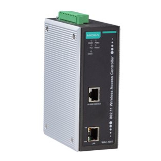
Package Checklist The WAC-1001 series wireless controller is shipped with the following items. If any of these items are missing or damaged, please contact your customer service representative. - Page 3 Panel Layout of the WAC-1001 Series 1. Grounding screw 2. Terminal block for PWR1, PWR2, relay, DI1, and DI2 3. Reset button 4. Heat dissipation orifices 5. System LEDs: PWR1, PWR2, PoE, FAULT, and STATE LEDs 6. RS-232 console port 7.
-
Page 4: Mounting Dimensions
Mounting Dimensions DIN-Rail Mounting The aluminum DIN-Rail attachment plate should already be fixed to the back panel of the WAC-1001 when you take it out of the box. If you need to reattach the DIN-Rail attachment plate to the WAC-1001, make sure the stiff metal spring is situated towards the top as shown in the figures below. -
Page 5: Wall Mounting
Wall Mounting For added convenience, the WAC-1001 can be wall mounted as illustrated below. STEP 1: Remove the aluminum DIN-Rail attachment plate from the WAC-1001, and then attach the wall mount plates with M3 screws, as shown on the right. STEP 2: Mounting the WAC-1001 to a wall requires 4 screws. -
Page 6: Wiring Requirements
Wiring Requirements WARNING Safety First! Be sure the power cord is disconnected before installing and/or wiring your WAC-1001. WARNING Safety First! Calculate the maximum possible current in each power wire and common wire. Observe all electrical codes dictating the maximum current allowed for each wire size. If the current goes above the maximum rating, the wiring could overheat, causing serious damage to your equipment. -
Page 7: Wiring The Redundant Power Inputs
Wiring the Redundant Power Inputs Two pairs of contacts of the 10-contact terminal block connector on the WAC-1001’s top panel are used for the WAC-1001’ two DC inputs. Top and front views of the terminal block connector are shown here. STEP 1: Insert the negative/positive DC wires into the V-/V+ terminals. -
Page 8: Cable Holder Installation (Optional)
Cable Holder Installation (Optional) You may choose to attach the cable holder to the bottom of the WAC-1001. This helps to keep cabling neat and avoid accidents caused from cluttered cables. STEP 1: Screw the cable holder onto the bottom of the WAC-1001. -
Page 9: Front Panel Leds
Console Pinouts for 10-pin or 8-pin RJ45 10-Pin Description 8-Pin ----- ----- NOTE 1. The pin numbers for the male DB9 and DB25 connectors, and hole numbers for the female DB9 and DB25 connectors are labeled on the connector. However, the numbers are typically very small, so you may need to use a magnifying glass to see the numbers clearly. -
Page 10: Specifications
Color State Description TP Port LED Indicators (Port Interface) TP port’s 100Mbps link is active 100M Green Blinking Data is being transmitted at 100 Mbps TP port’s 100Mbps link is inactive. TP port’s 10Mbps link is active. Amber Blinking Data is being transmitted at 10 Mbps TP port’s 10Mbps link is inactive. - Page 11 ATTENTION The WAC-1001 is NOT a portable mobile device and should be located at least 20 cm away from the human body. The WAC-1001 is NOT designed for use by the general public. A well-trained technician is required to safely deploy the WAC-1001 and establish a secure wireless network.
Need help?
Do you have a question about the WAC-1001 Series and is the answer not in the manual?
Questions and answers