Table of Contents
Advertisement
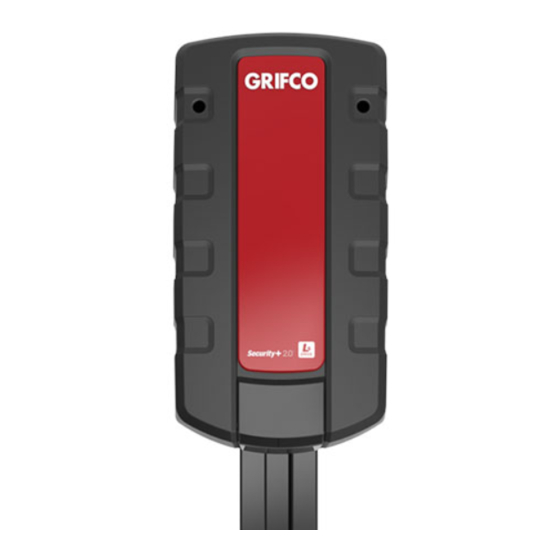
INSTRUCTION MANUAL
LS-Drive
GLD-SDO
LS-Drive Operator
GLD-R2.4M
Rail for (max) 2.4m High Door
GLD-R3.0M
Rail for (max) 3.0m High Door
Commercial Sectional Door Operator
• THIS OPERATOR IS TO BE INSTALLED AND SERVICED BY A TRAINED TECHNICIAN ONLY
• This operator is compatible with Security+ 2.0
Chamberlain Australia Pty Ltd
Unit 1, 75 Epping Rd North Ryde NSW 2113
Ph: 1800 GRIFCO
www.grifco.com.au
Ref: 114A4934B
®
accessories
OPERATOR
OPERATOR
SUPPLIED WITH GRIFCO
SUPPLIED WITH GRIFCO
MONITORED ENTRAPMENT
MONITORED ENTRAPMENT
PROTECTION
PROTECTION
Advertisement
Table of Contents

Related Manuals for Grifco GLD-SDO


Summary of Contents for Grifco GLD-SDO
- Page 1 INSTRUCTION MANUAL LS-Drive OPERATOR OPERATOR GLD-SDO SUPPLIED WITH GRIFCO SUPPLIED WITH GRIFCO LS-Drive Operator MONITORED ENTRAPMENT MONITORED ENTRAPMENT PROTECTION PROTECTION GLD-R2.4M Rail for (max) 2.4m High Door GLD-R3.0M Rail for (max) 3.0m High Door Commercial Sectional Door Operator • THIS OPERATOR IS TO BE INSTALLED AND SERVICED BY A TRAINED TECHNICIAN ONLY ®...
-
Page 2: Safety Symbol And Signal Word Review
Use the commercial sectional door operator for its intended purpose. The rise exceeds 50°C all fixed wiring insulation must be protected, for GLD-SDO operator is designed lifting spring-balanced sectional doors. example, by insulating sleeving having an appropriate temperature rating. If the supply cord is damaged, it must be replaced by the manufacturer, its service agent or similarly qualified persons in order to avoid a hazard. -
Page 3: Table Of Contents
INTRODUCTION CONTENTS SAFETY SYMBOL AND SIGNAL WORD REVIEW ......................2 INTRODUCTION ................................3 OPERATOR SPECIFICATIONS ................................4 OPERATOR OVERVIEW ..................................5 CONTROL PANEL OVERVIEW ................................5 CARTON INVENTORY ....................................6 TOOLS REQUIRED ....................................6 HARDWARE PROVIDED ..................................6 INSTALLATION ................................7 CONNECT RAIL TO OPERATOR ................................7 TIGHTENING THE CHAIN ..................................7 FASTENING RAIL TO OPERATOR .................................7 HEADER BRACKET POSITIONING ................................8 INSTALL HEADER BRACKET .................................8... -
Page 4: Operator Specifications
INTRODUCTION OPERATOR SPECIFICATIONS Power Specifications Main AC Power Supply 230-240 Vac 50Hz Max. Pull Force 1,200N Power 225W Operating Temperature +5°C to +40°C Door Specifications Max Door Height 3.0m Max Door Weight 160kg Max Lift under Spring Tension 20kg Normal Torque Maximum Door Area Commercial Spring-Balanced Sectonal Doors up to 15m²... -
Page 5: Operator Overview
INTRODUCTION OPERATOR OVERVIEW Hanging bracket Chain Operator Mounting Header Bracket Trolley Bracket Power cord Door arm Manual Release Rail Operator J-Bar Door Connection Bracket CONTROL PANEL OVERVIEW Control Panel is accessible under the cover on the rear of the operator. 6. -
Page 6: Carton Inventory
INSTALLATION CARTON INVENTORY NOTE The commercial sectional door operator is supplied in two separate cartons. GLD-SDO contains the operator, fitting hardware and accessories. GLD-R2.4M or GLD-R3.0M contain the complete, assembled rail and some hardware. Grifco 4-Channel Transmitter Hanging Brackets Operator... -
Page 7: Installation
INSTALLATION WARNING Before beginning installation of the operator check the door is in good mechanical condition, opens and closes properly and correctly balanced STEP 1 CONNECT RAIL TO OPERATOR Your door operator and rail are packed in two separate cartons. Remove the operator, rail and all the hardware in preparation for assembly. -
Page 8: Header Bracket Positioning
INSTALLATION STEP 4 HEADER BRACKET POSITIONING The header bracket must be fastened rigidly to a structural support. Reinforce the wall with a 40mm board if necessary. With the door closed, mark the vertical centre line of the door. Extend line upward onto header wall above door. -
Page 9: Position The Operator
INSTALLATION Rail should be mounted 50mm above the highest STEP 7 point of door travel POSITION THE OPERATOR Disengage the trolley mechanism (see section “Operating the manual release”) and slide it back towards the operator. Secure the hanging push arm up into the rail assembly temporarily using tape or rope, to avoid a hazard. -
Page 10: Attach Door Arm To Trolley
This will re-engage the trolley, and when the door passes the trolley position it will automatically re-engage the operator. www.grifco.com.au www.grifco.co.nz RISK OF ENTRAPMENT Repeat Safety Reverse Test monthly. Door must reverse on contact with a 40mm obstacle placed on the floor. -
Page 11: Commissioning
COMMISSIONING WARNING STEP 12 WHEN SETTING THE TRAVEL LIMITS, ENSURE PEOPLE ARE CLEAR OF THE MOVING DOOR PROGRAM THE TRAVEL LIMITS AND FORCE SETTINGS TO AVOID INJURY. Travel limits regulate the points at which the door will stop when moving UP or DOWN. The Without a properly installed safety travel limit buttons are located under the access cover on the rear panel (Figure 1) reversal system, persons... -
Page 12: Install The Entrapment Protection System
Disconnect power to the operator before safety beams. They must be installed for the operator to function. installing the safety beams. LS-Drive is not compatible with Grifco GPS15 reflective safety beams or GLCPS Light Curtain Protector System. Figure 1 The Safety Beams are supplied preassembled, complete with two Safety Beams, wiring and wall brackets. -
Page 13: Setting Timer-To-Close (Ttc)
COMMISSIONING WARNING STEP 14 Door may operate unexpectedly, therefore do not allow anything to stay in the path of the door. SETTING TIMER-TO-CLOSE Operation: Figure 1 This feature allows the door to automatically close from a fully open position after a specified time. The delay can be set from 10 to 180 Indicator LED seconds in 10 second increments, by using the buttons on operator control panel. -
Page 14: Types Of Security +2.0 Transmitters
COMMISSIONING TYPES OF SECURITY +2.0 REMOTE ACCESS DEVICES All Grifco remote access devices feature Security +2.0 technology. This With inbuilt perpetual rolling code technology, Grifco Security +2.0 advanced platform cuts through interference, and ensures consistent, transmitters are safe and secure. All devices feature exceptional battery life, reliable, long range operation of your commercial door. -
Page 15: Commissioning Remote Transmitters
COMMISSIONING WARNING COMMISSIONING REMOTE ACCESS DEVICES Activate the operator only when door is in full view, free of obstruction and properly NOTE: The transmitter supplied with your operator is adjusted. No one should enter or leave garage preprogrammed by the factory. while door is in motion. -
Page 16: Maintenance And Care
MAINTENANCE AND CARE USING YOUR OPERATOR WARNING 1. Your operator can be activated by any of the following devices: Before opening the door manually, ensure • Operator control panel: Up and Down Buttons door is at its CLOSED limit position if possible. •... -
Page 17: Troubleshooting
TROUBLESHOOTING TROUBLESHOOTING 7. Door opens but won't close: 1. Operator doesn't operate from either door control or remote: • Check Safety Beams. If the light on the Safety Beams are • Does the operator have electric power? Plug lamp into flashing, correct the alignment. -
Page 18: Diagnostics
DIAGNOSTICS The operator is programmed with self-diagnostic capabilities. The UP and DOWN arrows on the control panel indicate the diagnostic code. DIAGNOSTIC CODE SYMPTOM POSSIBLE RESOLUTION UP Arrow DOWN Arrow Flashes Flashes The operator will not close and Safety sensors wires may have been reversed, cut or the courtesy light flashes. -
Page 19: Service And Repair Parts
SERVICE AND REPAIR PARTS If the supply cord is damaged, it must be Power cord replaced by the manufacturer, its service agent or similarly qualified persons 026B0181 in order to avoid hazard. Control panel assembly 002A1966 Passpoint assembly 002A1965 Transformer 041A4027 Power board LED module... -
Page 20: Chamberlain Limited Warranty
Chamberlain’s warranty Chamberlain warrants to the original purchaser of the Grifco product (Unit) that: 1 The LS-Drive Unit (including electric motor) is free from defects in materials and workmanship for a period of 12 months from the date of purchase or 20,000 cycles (whichever comes first).
Need help?
Do you have a question about the GLD-SDO and is the answer not in the manual?
Questions and answers