Table of Contents
Advertisement
Quick Links
Operation - Repair - Parts
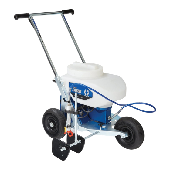
Sports Field Marker
For field marking applications only
IMPORTANT SAFETY INSTRUCTIONS
Read all warnings and instructions in this manual
and on the unit. Be familiar with the controls and
the proper usage of the equipment.
Save these instructions.
All Models:
Maximum Working Pressure 1200 psi (8.3 MPa, 83 bar)
Charger
Model
Voltage
24N950
120V
24R023
240V
24R370
240V
24R371
120V/240V
WARNING
FIRE AND EXPLOSION HAZARD
Solvent and paint fumes can ignite or explode.
•
Use only water-based materials. Do not use
materials which state "FLAMMABLE" on the
packaging. For more information about your
material, request MSDS from distributor or
retailer.
•
Do not spray or flush with flammable materials.
Series
B
B
B
B
[goto] Graco S90 FieldLazer - 24N950
332119E
EN
ti24682a
Advertisement
Table of Contents

Related Manuals for Graco 24N950


Summary of Contents for Graco 24N950
- Page 1 WARNING ti24682a FIRE AND EXPLOSION HAZARD Solvent and paint fumes can ignite or explode. [goto] Graco S90 FieldLazer - 24N950 • Use only water-based materials. Do not use materials which state “FLAMMABLE” on the packaging. For more information about your material, request MSDS from distributor or retailer.
-
Page 2: Table Of Contents
Adjusting Line Width ..... 14 Graco Standard Warranty ....38 Shutdown and Cleaning . -
Page 3: Warnings
Check hoses and parts for signs of damage. Replace any damaged hoses or parts. • This system is capable of producing 1200 psi (8.3 MPa, 83 bar). Use Graco replacement parts or accessories that are rated a minimum of 1200 psi (8.3 MPa, 83 bar). - Page 4 Do not leave battery unattended while charging. • Immediately unplug charger and remove battery when charging is complete. • Charge only Graco approved batteries listed in this manual; other batteries may burst. • Use only in dry locations. Do not expose to water or rain. •...
- Page 5 Warnings WARNING PERSONAL PROTECTIVE EQUIPMENT Wear appropriate protective equipment when in the work area to help prevent serious injury, including eye injury, hearing loss, inhalation of toxic fumes, and burns. This protective equipment includes but is not limited to: • Protective eyewear, and hearing protection.
-
Page 6: Component Identification
Component Identification Component Identification 332119E... -
Page 7: Component Identification List
Component Identification Component Identification List Material Dispenser Height Adjustment Knob Spray Button Material Dispenser Arm Adjustment Knob Battery Shroud (battery inside) Spray Shields Battery Charger Connection Port Motor Plug Prime/Spray Valve Spray Button Plug Material Dispenser Paint Hopper Screen/Ball Knocker Filter Tilt-N-Pour Paint Hopper Spray Tip/Guard Assembly... -
Page 8: Charging The Battery (Series A)
(C) on field marker. Battery charger is for indoor use only. Do not expose charger to rain or snow. Charge battery with Graco-approved charger. NOTE: Fully charge battery prior to first use. 1. Place field marker in a dry, well-ventilated area... -
Page 9: Charging The Battery (Series B)
Battery charger is for indoor use only. Do not expose charger to rain or snow. Charge battery with Graco-approved charger. NOTE: Fully charge battery prior to first use. 1. Place field marker in a dry, well-ventilated area away from flammable or combustible materials, including paints and solvents. -
Page 10: Common Procedures
Common Procedures Common Procedures Prime/Spray Valve Install Spray Tip/Guard Assembly (if not installed) Perform the Pressure Relief Procedure before installing spray tip/guard assembly. ti20183a ti20184a Put prime/spray valve (D) UP to release pressure. UP position DOWN position (For priming and releasing (Ready to spray) ti14999a pump pressure) -
Page 11: Reversible Spray Tip
Common Procedures Reversible Spray Tip Filter Removal / Cleaning Always perform Pressure Relief Procedure before Always perform Pressure Relief Procedure before adjusting spray tip position. removing filter. In the event that particles or debris clog the spray tip, Perform Pressure Relief Procedure, page 10. this field marker is designed with a reversible spray tip that can be used to quickly and easily clear the particles and resume spraying as quickly as possible. -
Page 12: Spraying
Common Procedures Spraying Emptying the Paint Hopper Press spray button (A) to spray. Spray will continue until 1. Place striping machine near the material container. spray button is pressed again to stop. 2. Remove paint hopper lid. 3. Grab front of paint hopper (S) and slowly lift. Material will pour back into the material container. -
Page 13: Starting A New Job
Starting a New Job Starting a New Job a. To fill field marker with fluid, press spray button (A) and allow field marker to run until material flows through prime hose. 1. Perform Pressure Relief Procedure, page 10. ti20212a ti21316a b. -
Page 14: Adjusting Line Width
3. Adjust height of tip to adjust line width (raising tip height will create wider lines). NOTE: Different tip sizes are available for lines greater than 6 in. (15 cm) wide. Use Graco part number LL5417 for wider lines. 332119E... -
Page 15: Shutdown And Cleaning
Fill paint hopper with 1/2 gallon (2 liters) water. and the warranty will no longer be valid. Do not store solvents in field marker. Always flush with Graco Pump Armor prior to storage. Flushing Field Marker ti20211a Put prime/spray valve (D) UP to clean prime hose. -
Page 16: Optional Cleanup
Shutdown and Cleaning Optional Cleanup: • • Clean out paint hopper at a sink. Perform Pressure Relief Procedure, page 10. • • Install paint hopper onto field marker. Empty the paint hopper, see page 12. • Disconnect motor plug (N) and remove material •... -
Page 17: Unclogging Spray Tip/Guard Assembly
Shutdown and Cleaning Unclogging Spray Tip/Guard Assembly Push spray button again to stop field marker. Perform Pressure Relief Procedure, page 10. Always perform Pressure Relief Procedure before Rotate spray tip (X) back to SPRAY position. unclogging spray tip/guard assembly. Perform Pressure Relief Procedure, page 10. ti20191a Put prime/spray valve DOWN to spray position. -
Page 18: Storage
Storage Storage Press spray button to stop when Pump Armor flows through prime hose. Move prime/spray valve (D) DOWN to the spray position. NOTICE Failure to store field marker with Pump Armor will result in operational problems the next time you spray. Always circulate Pump Armor through the field marker after cleaning. -
Page 19: Repair
Repair Repair Tip Removal/Cleaning CleanShot Cleaning (If ™ applicable) 1. Perform Pressure Relief Procedure, page 10. 1. Perform Pressure Relief Procedure, page 10. 2. Remove spray tip/guard assembly (G). ti20183a 2. Rotate spray tip (X) 1/4 turn and remove. ti21382a 3. - Page 20 Repair 5. Hold CleanShot over running water and clean. Work 8. Install CleanShot assembly. needle in and out to free CleanShot from excess or hardened material. ti21385a 6. Use two wrenches to install needle seat. ti21395a 9. Install spray tip/guard assembly (G). ti21501a ti21402a 7.
-
Page 21: Fuse Replacement
Repair Fuse Replacement Installation 1. Insert a new standard 30 A automotive fuse (Regu- lar ATO) fuse into fuse case. Removal 2. Place front tabs of battery shroud into slots, then 1. Perform Pressure Relief Procedure, page 10. pivot back of shroud down. Use wrench to tighten two bolts and secure shroud into place. -
Page 22: Battery Replacement
Repair Battery Replacement 4. Use wrench to remove two bolts and remove battery shroud (B). Removal 1. Perform Pressure Relief Procedure, page 10. ti21369a 5. Use two wrenches to remove serrated nut on nega- tive (black) battery post. Then use wrenches to remove serrated nut on positive (red) battery post. - Page 23 Repair Installation 1. Install new battery. Install bolts and nuts onto NOTICE battery posts with terminals facing front of field marker. Tighten velcro strap around battery to When installing the battery shroud, wires can get secure into place. pinched between the shroud and frame and become damaged.
-
Page 24: Control Board Replacement
Repair Control Board Replacement Installation 1. Install new board into battery shroud. Tighten six torx screws into board. Removal 2. Connect negative wire (black) to outer connector of 1. Disconnect battery wires. See Battery charger jack. Connect positive wire (red) to inner Removal steps 1 - 5, page 22. -
Page 25: Pump/Motor Removal
Repair Pump/Motor Removal Removal 1. Perform Pressure Relief Procedure, page 10. ti21373a 6. Disconnect motor wires and remove power cord. ti20183a ti21374a 2. Disconnect motor plug (N). 7. Use wrench to remove bulkhead nut. ti21484a ti21377a 3. Use wrench to disconnect hose to material dispenser. - Page 26 Repair 11. Remove pump/motor assembly from hopper 2. Install Pump/Motor assembly into paint hopper (S). bracket. ti21394a 3. Install and tighten four screws. ti24689a ti21400a Installation 4. Install and tighten hose clamp to paint hopper. 1. Loosely install hose clamp on pump before installing pump/motor assembly onto pump bracket.
- Page 27 Repair 6. Install power cord and connect motor wires. 8. Install paint hopper (S). Connect white wire to post with red indicator mark. Connect black wire to outside post. Black White Wire Wire ti21374a ti21486a 7. Install motor shroud, capture wire strain relief and 9.
-
Page 28: Troubleshooting
STOP and contact Graco Technical Support or bring field marker to Graco distributor for repair. NOTE: Red light on spray button will be flashing. Pump/motor is damaged Remove pump/motor for repair. - Page 29 Cleaning, page 19. spray CleanShot is damaged. Contact Graco Technical Support or bring field marker to Graco distributor for repair. Battery did not fully charge Battery charger was disconnected too Disconnect charger from field marker. Disconnect...
-
Page 30: Wiring Diagram
Wiring Diagram Wiring Diagram WHITE BLACK RED DOT MOTOR SWITCH ORANGE OR YELLOW FUSE Automotive BLACK Regulator ATO CONTROL BOARD BATTERY BLACK CHARGER JACK ti21412a 332119E... -
Page 31: Parts
Parts Parts 103a 103b 103c ti24691a 332119E... -
Page 32: Parts List
Parts Parts List Ref. Part Description Ref. Part Description 127052 KNOB, T-handle 16U476 FRAME, stamped, S90 126949 STRAP, battery 16U478 BRACKET, frame, right 114659 GRIP, handle 16U477 BRACKET, frame, left 24P924 SWITCH, pushbutton 24R069 BAR, handle, weldment 16U160 BATTERY, 18 ah, sealed 16U580 AXLE, rear, S90 16U707 HARNESS, motor wire 126946 BOLT, cap, hex head... -
Page 33: Parts
Parts Parts ti24693a 332119E... -
Page 34: Parts List
Parts Parts List Ref. Part Description Ref. Part Description 192348 NUT, head 22‡ 24R795 KIT, hopper, S90, 127962 SPRING includes 24, 25, 53, 54, 119 17C934 STEM, ball knocker 16U373 SEAL, lid, hopper 17C935 KNOB 126108 SCREW, shoulder, socket head 16U679 LABEL, brand, S90, hopper, lside 24R883 KIT, cover, S90 pump, includes 43 16U677 LABEL, brand, S90, hopper, rside... -
Page 35: Parts
Parts Parts Optional CleanShot™ Valve Replaces 70, 70a, 70b ti24704a 332119E... -
Page 36: Parts List
Parts Parts List Ref. Part Description Ref. Part Description 17C501 HOUSING, filter, turf 15D862 NUT, hand 104319 O-RING, packing 24P124 KIT, holder, tip, includes 31-79 17C500 HOUSING, restrictor 277183 HOSE, cpld, 3/16 in. x 6 ft, 3300 wp 103875 ADAPTER, hose, barb 16T159 MANIFOLD, filter 16U667 TUBE, drain 16U255 HOLDER, tip... -
Page 37: Technical Data
Technical Data Technical Data U.S. Metric Maximum working pressure 1200 psi 8.3 MPa, 83 bar Recommended Tip Size LL5315 LL5315 Maximum Tip Size LL5417 LL5417 Weight 60 lb 27.2 kg Dimensions: Length 40 in. 101.6 cm Width 23 in. 58.4 cm Height 36 in. -
Page 38: Graco Standard Warranty
With the exception of any special, extended, or limited warranty published by Graco, Graco will, for a period of twelve months from the date of sale, repair or replace any part of the equipment determined by Graco to be defective.
Need help?
Do you have a question about the 24N950 and is the answer not in the manual?
Questions and answers