Advertisement
Quick Links
ULTRA SAUNA HEATER INSTALLATION
BEFORE YOU START
*Heater must be installed by a licensed electrician*
Heater must be installed according to local codes.
Plastic must be removed from shell before operating heater.
Sauna door must always open outward.
Sauna door can never include a lock.
Do not install more than one heater in a room.
YOUR HEATER SHOULD INCLUDE
Controls
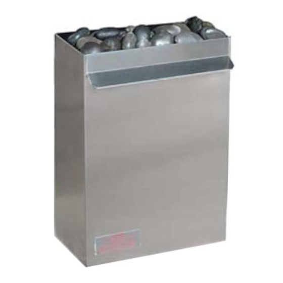
Main Heater Unit
High Density Sauna Rocks
Installation Instructions
Warranty / Registration Card
Warning Sign
Sauna Room General Guidelines
The sauna should be constructed of clear western red cedar.
Plastic must be removed from shell before operating heater.
Do not treat or varnish the sauna wood.
Fill the heater only with Scandia high-density rocks
Check and clean rocks and rock tray twice a year.
The warning signs and sauna usage plaque must be displayed.
Sauna room sizing is based on standard 7 foot ceilings.
Only use an aroma-stone when using fragrances
Do not touch the heater while in operation
Do not cover the heater
Never hose down the sauna
Never leave children unattended
Sauna bathing is not suitable for those with health problems.
Consult a doctor before using
HEATER SIZING
Sauna Room Venting Guidelines
Sauna room should be vented according to manufacturers
specifications or Scandia sauna room specification found in
the Scandia sauna installation instructions. Improper ventila-
tion is dangerous for the sauna users health. The inlet vent
should be below the heater or near the base of the heater.
Outlet vent can be just below the top bench on the opposite
side, near the opposite side of the heater or you may under-
cut the sauna door. When the door is under cut you should
have between 3/4" to 1" between the finished floor and the
bottom of the door.
Advertisement

Subscribe to Our Youtube Channel
Related Manuals for scandia 30240


Summary of Contents for scandia 30240
- Page 1 Plastic must be removed from shell before operating heater. Do not treat or varnish the sauna wood. Fill the heater only with Scandia high-density rocks Check and clean rocks and rock tray twice a year. The warning signs and sauna usage plaque must be displayed.
- Page 2 Sauna Heater and Guard Rail Placement Guide Chassis Small Medium Large Description 3KW‐4.5KW 6.0KW‐9.0KW 12KW‐18KW A Width Of Heater Shell 16" 16" 26" B Wall to Face of Heater 10 3/4" 14" 18" For additional information, technical assistance or trouble shooting please C Side of Heater to Wall (Min.) 5" 5" 8" ...
-
Page 3: Control Box Location
F Control Wiring—60 Minute Timer Control Box Location C om m ercial Installations – M ost com m ercial facilities w ith 24 hour tim ers place the control panel in a service room near the sauna or the electrical room . W hen the room is not near the sauna the therm ostat can be placed near the room separate from the control box . - Page 4 H Control Wiring—60 Minute Timer Control Box Location C om m ercial Installations – M ost com m ercial facilities w ith 24 hour tim ers place the control panel in a service room near the sauna or the electrical room . W hen the room is not near the sauna the therm ostat can be placed near the room separate from the control box .
- Page 5 B Control Wiring—60 Minute Timer-Single Phase C o ntro l B o x L o c a tio n C o m m e rc ia l Ins ta lla tio n s – M o s t c o m m e rcial fa c ilitie s w ith 2 4 h o u r tim e rs p la c e th e c o n tro l p a n e l in a se rvic e ro o m n e a r th e s a u n a o r th e e le c tric a l ro o m .
- Page 6 A Control Wiring—60 Minute Timer-Single Phase C o ntro l B o x L o c a tio n C o m m e rc ia l Ins ta lla tio n s – M o s t c o m m e rcial fa c ilitie s w ith 2 4 h o u r tim e rs p la c e th e c o n tro l p a n e l in a se rvic e ro o m n e a r th e s a u n a o r th e e le c tric a l ro o m .
- Page 7 A2-24 Control Wiring- 24 Hour Timer—Single Phase C o ntro l B o x L o c a tio n C o m m e rc ia l Ins ta lla tio n s – M o s t c o m m e rcial fa c ilitie s w ith 2 4 h o u r tim e rs p la c e th e c o n tro l p a n e l in a se rvic e ro o m n e a r th e s a u n a o r th e e le c tric a l ro o m .
- Page 8 A3 Control Wiring— 60 Minute Timer—Three Phase C o ntro l B o x L o c a tio n C o m m e rc ia l Ins ta lla tio n s – M o s t c o m m e rcial fa c ilitie s w ith 2 4 h o u r tim e rs p la c e th e c o n tro l p a n e l in a se rvic e ro o m n e a r th e s a u n a o r th e e le c tric a l ro o m .
- Page 9 A3-24 Control Wiring—24 Hour Timer-Three Phase C o ntro l B o x L o c a tio n C o m m e rc ia l Ins ta lla tio n s – M o s t c o m m e rcial fa c ilitie s w ith 2 4 h o u r tim e rs p la c e th e c o n tro l p a n e l in a se rvic e ro o m n e a r th e s a u n a o r th e e le c tric a l ro o m .
- Page 10 E2 Control Wiring—60 Minute Timer-Three Phase C o ntro l B o x L o c a tio n C o m m e rc ia l Ins ta lla tio n s – M o s t c o m m e rcial fa c ilitie s w ith 2 4 h o u r tim e rs p la c e th e c o n tro l p a n e l in a se rvic e ro o m n e a r th e s a u n a o r th e e le c tric a l ro o m .
- Page 11 E2 Control Wiring 60 Minute Timer-Single Phase C o ntro l B o x L o c a tio n C o m m e rc ia l Ins ta lla tio n s – M o s t c o m m e rcial fa c ilitie s w ith 2 4 h o u r tim e rs p la c e th e c o n tro l p a n e l in a se rvic e ro o m n e a r th e s a u n a o r th e e le c tric a l ro o m .
- Page 12 E2-24 Control Wiring—24 Hour Timer-Three Phase C o ntro l B o x L o c a tio n C o m m e rc ia l Ins ta lla tio n s – M o s t c o m m e rcial fa c ilitie s w ith 2 4 h o u r tim e rs p la c e th e c o n tro l p a n e l in a se rvic e ro o m n e a r th e s a u n a o r th e e le c tric a l ro o m .
- Page 13 E2-24 Control Wiring—24 Hour Timer-Single Phase C o ntro l B o x L o c a tio n C o m m e rc ia l Ins ta lla tio n s – M o s t c o m m e rcial fa c ilitie s w ith 2 4 h o u r tim e rs p la c e th e c o n tro l p a n e l in a se rvic e ro o m n e a r th e s a u n a o r th e e le c tric a l ro o m .
-
Page 14: Circuit Breaker
Wires from Control/Heater single 208/240 28.9 3qty #8 ‐ 2qty #14 FC controls (6000W ) 208V single phase G round Three Phase Power Feed Scandia electric heaters are U L listed G round Term inal Therm ostat Contactor High Lim it Switch Tim er Elem ent 2... - Page 15 Standard Heater/Control Configuration For additional information, technical Line Feeds /Ground From B reaker assistance or trouble shooting please www.scandiamfg.com visit: Therm ostat S ensor B ulb *Note: controls to be located outside of sauna C ontrol H eater W arning Signs Line feeds/ground from C ontrol box to H eater...
Need help?
Do you have a question about the 30240 and is the answer not in the manual?
Questions and answers