Table of Contents
Advertisement
Quick Links
Advertisement
Table of Contents

Related Manuals for Powr-Flite CAS16


Summary of Contents for Powr-Flite CAS16
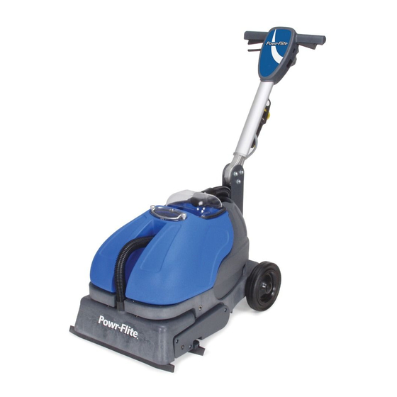
- Page 1 OPERATOR’S MANUAL & PARTS LIST COMPACT AUTOMATIC SCRUBBER Model CAS16 WARNING: OPERATOR MUST READ AND UNDERSTAND THIS MANUAL COMPLETELY BEFORE OPERATING THIS EQUIPMENT. © Tacony, Inc., All rights reserved CAS16-Man 7/2016 Save These Instructions...
-
Page 2: Important Safety Advice
SAVE THESE INSTRUCTIONS FOR FUTURE REFERENCE *When using an electrical scrubber, basic precautions should be followed. *Read all instructions before using your scrubber. IMPORTANT SAFETY ADVICE PREPARING FOR USE When using electrical equipment basic safety precautions should be fol- Before connecting the machine to the power supply, check that the sup- lowed including the following: ply voltage corresponds with that marked on the rating label on the rear of the machine. -
Page 3: Operation
CONTROLS The operating controls are located on the handle. Brush motor switch Used to switch motor ON and OFF. Lights when in the ON position. Neon indicator Lights when the machine is connected to the power supply Vacuum motor switch Neon indicator Brush motor switch Vacuum motor switch... -
Page 4: Changing The Brush
MAINTENANCE CHANGING THE BRUSH WARNING – This has been designed for use with the brushes specified by the manufacturer. The fitting of other brushes may affect its safety. Always ensure machine is unplugged before fitting or removing parts. 1. To change the brush, first remove both the recovery and solution tanks. 2. -
Page 5: Troubleshooting
TROUBLESHOOTING The following simple checks may be performed by the operator Problem Reason Remedy Machine not working, motors not running. Lack of voltage/electrical supply. Check supply cord, plug and socket outlet. Vacuum motor not running, switch illuminated. Faulty motor. Contact service. Brush shaft incorrectly positioned. - Page 6 Model CAS16 Parts...
- Page 7 Drawing Assembly / Part Description / Part Number Ref. Number SSD400/110/60/PO SCRUBBER DRYER POWER-FLITE(110V US) HANDLE 05-4351-0000 SSD400 110V US HANDLE ASSEMBLY INCLUDES THE FOLLOWING PARTS: 02-3151-0000 P CLIP 02-3152-0000 CABLE STRAIN RELIEF BRACKET 02-3511-0000 GEAR DOG SPRING 02-3520-0000 DIAPHRAGM GROMMET 02-3736-0000 DBLE SIDED TAPE 0.05 02-4492-0000 SPLASH PROOF COVER...
- Page 8 Model CAS16 Parts 24 26 27 28...
- Page 9 Drawing Assembly / Part Description / Part Number Ref. Number 05-4342-0000 RECOVERY TANK ASSEMBLY INCLUDES THE FOLLOWING PARTS : 02-4536-0000 KNOCK OUT PLUG - NOT SHOWN ON DRAWING 03-7857-0039 RECOVERY TANK 03-7874-0020 RECOVERY TANK INLET COVER 03-7883-0000 RECOVERY TANK HANDLE PIN 03-7884-0000 RECOVERY TANK HANDLE 03-7893-0000 RECOVERY TANK INLET COVER SEAL 00-0516-0013 M5 x 16LG POZI PAN SCREW...
- Page 10 Model CAS16 Parts 123 124...
- Page 11 Drawing Assembly / Part Description / Part Number Ref. Number BASE ASSEMBLY INCLUDES THE FOLLOWING PARTS: 05-4199-0000 SOLUTION TANK ASSEMBLY INCLUDES THE FOLLOWING PARTS: 03-7858-0067 SOLUTION TANK 02-3445-0000 BULKHEAD COUPLING (METAL) 10-0062-0000 SOLUTION TANK FILTER KIT INCLUDES THE FOLLOWING PARTS: 03-6213-0000 FILTER ELEMENT WITH MOULDED END 03-6344-1000...
- Page 12 Model CAS16 Parts 147 148...
- Page 13 Drawing Assembly / Part Description / Part Number Ref. Number 00-0410-0011 SCREW M4 x 10 POZI PAN HD BZP 00-0606-0171 SCREW M6 x 6 SOCKET SET GRUB 00-0520-0011 M5 x 20 POZI PAN HEAD SCREW ZINC PLATED 10-0053-0000 DRIVE MOTOR PLATE KIT INCLUDES THE FOLLOWING PARTS: 02-3245-0000 CIRCLIP - 'E' TYPE D1500/5 STAINLESS STEEL 05-4205-0000...
- Page 14 Drawing Assembly / Part Description / Part Number Ref. Number 02-4523-0000 No.8 x 3/4"LG SELF TAPPING SCREW PAN HEAD ST/STL 10-0084-0000 CHASSIS KIT INCLUDES THE FOLLOWING PARTS: 05-4201-0000 CHASSIS ASSEMBLY CONSISTING OF: 02-4524-0000 GROMMET ID11.1 OD15.9 X 6.4THK 03-7862-0000 WHEEL AXLE 03-7863-0067 CHASSIS 02-3468-0000...
- Page 15 Model CAS16 Electrical Diagram...
- Page 16 In case you, as our customer, meet any trouble with your machine, contact a Powr-Flite representative, who will be happy to be of service to you and will take care of any warranty issues.
Need help?
Do you have a question about the CAS16 and is the answer not in the manual?
Questions and answers