Cerwin-Vega Vega Series User Manual
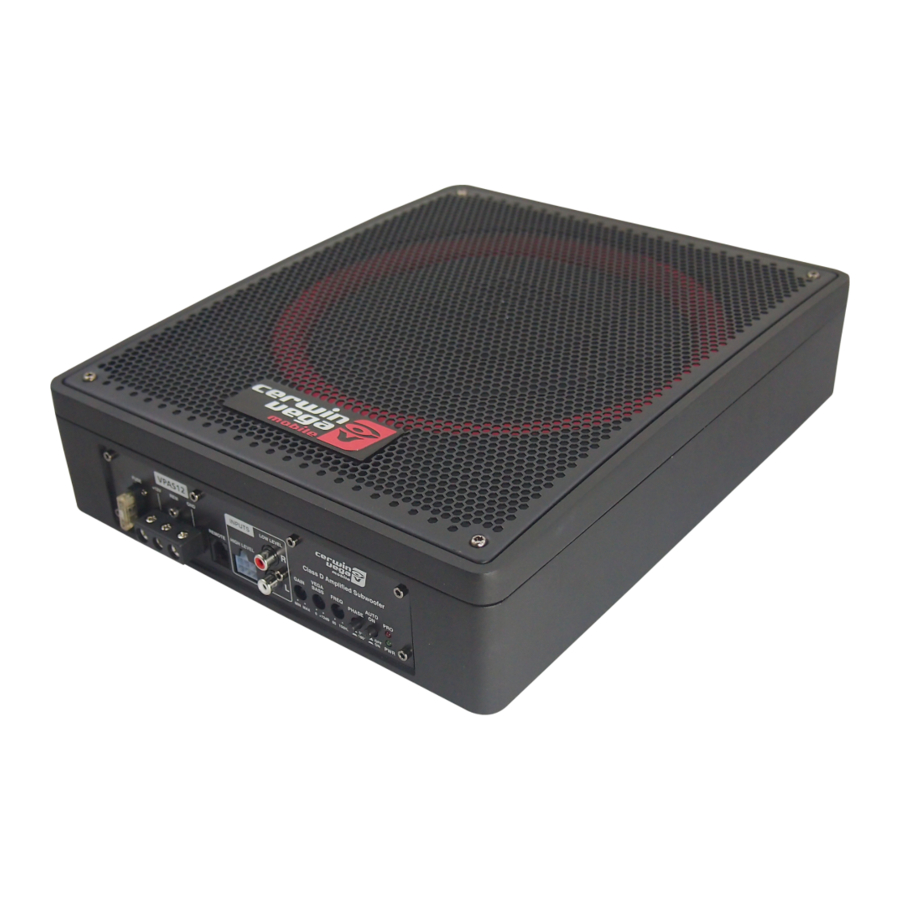
Digital amplifier
Hide thumbs
Also See for Vega Series:
- Manual (47 pages) ,
- User manual (13 pages) ,
- User manual (6 pages)
Table of Contents
Advertisement
Quick Links
Advertisement
Table of Contents

Related Manuals for Cerwin-Vega Vega Series


Summary of Contents for Cerwin-Vega Vega Series
- Page 2 Cerwin Vega Mobile Amplifiers Thank you for purchasing a Cerwin Vega Mobile amplifier for your car audio s ys tem. You have chosen Cerwin Vega Mobile because you deserve the best! Cerwin Vega Mobile amplifiers are designed and engineered to the highest quality standards in the industry to create the ultimate listening experience in your vehicle.
-
Page 3: Product Specifications
(0.7A) (0.7A) (0.7A) MOUNTING PRECAUTIONS Distortion Although Cerwin Vega Mobile amplifiers incorporate heat sinks and protection circuits, mounting the amplifier in a tight space THO 4 (l KHz@40) 0.05% 0.07% 0.031% without any air movement can still damage internal circuitry over time. Choose a locotion that provides adequate ventilation S/N Ratio (A weighted@lW) -77.2dBA... - Page 4 s CHRnnEL COfflPLETE SYSTEffl [UECiff UIIOO.SDJ uaaoo.z Front/Rear Speaker setup 5 Channel VEGA amplifier (Vl 100.5D) 10 47• /266mm UliDD.11.1 �- �.-.. © ®0® ® HEAD UNIT (perferredly with SV output) ®® UIIOO.S Subwoofer(MIN 20 load) ®®@0 ®...
- Page 5 @Power Fuses - Stondord automotive type ATC/ATO fuses ore used on Cerwin Vega Mobile amplifiers. Always replace with the correct fuse size. Never insert fuses of higher values. Doing so will void the warranty of your Cerwin Vega Mobile amplifier. Also include o main fuse at the connection to the vehicle battery within 18 inches of the positive bottery post.
- Page 6 UEC.R St.ereo RmpllFler Amplifiers (regardless of brand name) will put on increased load on the vehicle's batt e ry and charging system. Cerwin Vega ULI00.2 - St.ereo [2 ohms;] Mobile recommends checking your alternator and battery condition to ensure that the electrical system hos enough capacity to handle the increased load of your stereo system.
- Page 7 UEGR I.I channel Front. 5. Prepare the ground wire for attachment to the amplifier by stripping 5/8" of insulation from the end of the wire. Always [I.I speakers} use a wire of the same gauge as the power connection, never smaller. Insert the bare wire into the GND terminal and I.I channel rear [brlclgec:IJ tighten the set screw to secure the cable in place.
- Page 8 UECiFI - ._, Channel in Placing the x-over switch in the FULL position sets the amplifiers to Full Range. This setting allows ALL frequencies to pass 3 channel mode to the speakers. Placing the switch in the HPF or LPF position activates the l 2dB crossover. When the switch is set to HPF(High-Pass) or LPF (Low-Pass) the crossover adjustable is from 40-400 Hz (30-300 LPF on Vl 100.5D).
Need help?
Do you have a question about the Vega Series and is the answer not in the manual?
Questions and answers