Table of Contents
Advertisement
Quick Links
Advertisement
Table of Contents

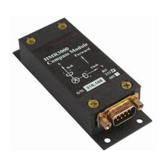
Related Manuals for Honeywell HMR3000


Summary of Contents for Honeywell HMR3000
- Page 1 HMR3000 Digital Compass Module User’s Guide 900240 Rev. B 3/01...
- Page 2 Packing List Part Number Items included HMR3000-D00-232 HMR3000 RS 232 Circuit Card Demo Software and Users Manual CD-Rom HMR3000-D00-485 HMR3000 RS 485 Circuit Card, Users Manual CD Rom HMR3000-D21-232 Housed Compass Module RS232 Demo Software Disk 1 and 2* Users Manual CD Rom...
- Page 3 Microsoft Excel (5.0 or greater) for capture and export of data (if desired) Note: The Graphical output of the HMR3000 on PC Demo software may become sluggish if the PC has slow graphic capability or if other applications are running in the background.
-
Page 4: Table Of Contents
2.10 C - RS485 O ................4 OMMUNICATION PTION 2.11 I ......................5 NSTALLATION 2.12 C ........................5 ALIBRATION OPERATION OF HMR3000 IN DETAIL ............6 GENERAL ........................6 HMR3000 ELECTRICAL BLOCK DIAGRAM..............7 HMR3000 PROCESS CONTROL BLOCK DIAGRAM..........8 ....................8 EASUREMENT EQUENCE ..................8 NTERFACE ESCRIPTIONS ......................9 OMMUNICATION ...........................9... -
Page 5: Introduction
The sophisticated auto compass calibration routines will correct for the magnetic effects of the platform. Wide dynamic range of the magnetometer (±1 G or 100 µT) allows the HMR3000 to be useful in applications with large local magnetic fields. -
Page 6: Hmr3000 Connection Diagram-Computer Rs232 To Hmr3000
Supply power to HMR3000 (6-15V at the unregulated power input or 5V regulated). If you purchased a HMR3000 Demonstration Kit, use the power and interface cable to connect between HMR3000 and your computer’s COM port. Make sure the line voltage selection (110 or 220V) in the adapter is appropriate and that 6 Vdc or higher output voltage (<15V) is selected. -
Page 7: Communication-Rs232 Option
Microsoft Excel (5.0 or greater) for capture and export of data (if desired) Note: The Graphical output of the HMR3000 on PC Demo software may become sluggish if the PC has slow graphic capability or if other applications are running in the background. -
Page 8: Configuring Hmr3000
Display \ Monitor NMEA Sentences The HMR3000 output can be changed to include all or any of the six NMEA sentences each with its own rate. User can capture the output messages to a file using the Capture Mode by selecting the message to be captured. -
Page 9: Installation
The HMR3000 Compass module’s RS-485 interface is half duplex, i.e. transmit and receive circuits share the same physical pair of wires. The HMR3000 must disable its transmitter to allow characters to be received from a host system. If the unit is operating in Run mode, i.e. -
Page 10: Operation Of Hmr3000 In Detail
A microprocessor controls the measurement sequence of the sensors, and all the parameters that control the operation are stored in an EEPROM. The output sentences of the HMR3000 conform to the NMEA 0813 standard for Marine communication. -
Page 11: Hmr3000 Electrical Block Diagram
Enter the compass in to user Hard Iron calibration mode HMR3000 ELECTRICAL BLOCK DIAGRAM Regulator 6–15 Vdc Tilt Sensor 2-Axis EEPRROM Continuous/Reset Micro Operate/Calibrate Magnetometers processor Run/Stop 3-Axis Ready/Sleep RS232 RS485 Analog Drive Circuits Figure 3. Electrical block diagram of HMR3000 900240 Rev. B 3/01 page 7... -
Page 12: Hmr3000 Process Control Block Diagram
HMR3000 PROCESS CONTROL BLOCK DIAGRAM User configurable parameters that control the measurement and heading calculation process is denoted at the bottom of the diagram in italic font. Sensors Microprocessor Output A, B Tilt IIR Filter Non Linear 6 NMEA Messages... -
Page 13: Interface Pin Descriptions
HMR3000 in Continuous Mode at the rates programmed in EEPROM. HMR3000 also responds to all input messages from the host. An HMR3000 response to a command input may be delayed due to transmission of an unsolicited output. The host must wait for HMR3000 to respond to the last command input before sending another command message. -
Page 14: Output
The ASCII display message is not expected to commingle with the other six NMEA messages. It is intended for simpler systems where the HMR3000 is connected to a numerical readout device instead of a host processor. - Page 15 Heading, Pitch, & Roll $PTNTHPR,x.x,a,x.x,a,x.x,a*hh<cr><lf> This sentence combines HMR3000’s three significant measurements with useful status information. Data fields represent, in order: heading, magnetic field status, pitch, pitch status, roll, and roll status. Heading, pitch, and roll measurements are presented in degrees or mils depending on the setting in EEPROM. The heading measurement is corrected for deviation and variation when these factors are programmed in the EEPROM.
- Page 16 This sentence provides raw tilt and magnetic measurements for diagnostic use. Contents of each field represent A/D readings for, in order: TiltAp, TiltAm, TiltBp, TiltBm, MagA, MagB, MagC, MagAsr, MagBsr, MagCsr. All values represent the actual A/D readings from the most recent conversions, except that tilt readings are adjusted if low gain was used for the conversion.
-
Page 17: Checksum Filed
3.11 Checksum Filed This absolute value is calculated by exclusive OR operation on 8 data bits (ASCII code) (no start or stop bits) of each character in the message, between, but excluding “$” and “*” (or between “#” and “*”) characters. The hexadecimal value of the most significant and the least significant 4 bits of the result is converted to two ASCII characters (0-9, A-F) for transmission. -
Page 18: Configuration Parameters
This section describes the configuration parameters that can be set using HMR3000’s configuration software. 4.1 O PERATIONAL Using the serial protocol described in the previous section, an external host can direct operation of the HMR3000 with the following commands: Command... -
Page 19: General Configuration Parameters
General Configuration Parameters The parameters in this section affect the general operation of the compass board. Parameter Name Description Command Syntax Degrees Sets the units for heading, pitch, and roll: #FA0.4=1*21<CR><lf> 1 = degrees (0.0 to 359.9) Mils 0 = mils (0 to 6399) #FA0.4=0*20<CR><lf>... -
Page 20: Measurement Parameters
Measurement Parameters Parameters in this section affect the measurement functions of the compass board. “Mag sample rate” is a key setting that affects both continuous and strobe mode measurements. In continuous mode, either 1, 2, 4, or 8 magnetometer measurements are averaged per tilt measurement depending on the “Mag sample rate” setting. In strobe mode, measurements are suspended until an NMEA query command is received. - Page 21 Query #WB4?*1E<CR><lf> Response MagX offset Hard-iron offset along north-south axis #IC4=nnnn*hh<CR><lf> (nnnn) in counts in magnetometer counts. Allows the user to input a value. Query #IC4?*01<CR><lf> Response N=Hard Iron offset (in counts) #N*hh<CR><lf> MagY offset Hard-iron offset along east-west axis #IC6=nnnn*hh<CR><lf>...
- Page 22 magnetic field status of the HPR output sentence when the total mag field value (Mag T) falls below the parameter setting. Query #WBC?*69<CR><lf> Response #nnnnn*hh<CR><lf> Pitch / roll alarm Sets the Over range alarm level for pitch #WE6=nn.n*hh<CR><lf> (nn.n) and roll. Issues an Alarm condition (P) in the Pitch or Roll status fields of the HPR output sentence when either pitch or roll output...
-
Page 23: Serial I/O
Serial I/O Parameters in this section affect the serial output functions of the compass board. Name Description Command Syntax Baud Rate Sets the Serial I/O Baud rate: Index Value (I) 1200 : (2) #BA4H=2T*24 <CR><lf> 2400 : (4) #BA4H=4T*22<CR><lf> 4800 : (8) #BA4H=8T*2E<CR><lf>... - Page 24 XDR has Pitch Include or exclude PITCH in XDR sentence Exclude #FA1.0=0*25<CR><lf> Include #FA1.0=1*24<CR><lf> Query #FA1.0?*17<CR><lf> Response m=1 (include), m=0 (exclude) #m*hh<CR><lf> XDR has Roll Include ROLL in XDR sentence #FA1.1=0*24<CR><lf> #FA1.1=1*25<CR><lf> Query #FA1.1?*16<CR><lf> Response m=1 (include), m=0 (exclude) #m*hh<CR><lf> XDR has MagX Include MAGX in XDR sentence #FA1.2=0*27<CR><lf>...
-
Page 25: Description Of Hardware Interrupt Pins
5.0 DESCRIPTION OF HARDWARE INTERRUPT PINS Detail description of the functionality of the Cont./Reset, Operate/Calibrate, Ready/Sleep, Run/Stop switches. The order of precedence for operation of the switch inputs is as follows (highest first): Setting "Cont. / Reset" low unconditionally holds the processor in its reset state. No other functions can be performed until the switch is returned to the "Continue"... -
Page 26: Physical Dimensions
7.0 PHYSICAL DIMENSIONS inches (centimeters) 4.200 (10.67) 3.250 (8. 26) 0.250 0.250 Φ 0.150 (0.38) (0.64) 0.188 (0.64) (0.46) 0.062 (0.16) Figure 5. Housed Compass Figure 6. Circuit Card 900240 Rev. B 3/01 page 22... - Page 27 4) Incorrect baud rate (19200 factory setting) chosen. Try other baud rates. 5) If this error did not occur during your last session with HMR3000, it may have been configured to send a large number of messages that the computer can not handle.
- Page 28 How to set the Baud Rate Through the PC Demo Interface 1) Connect the device and run PC Demo 2) Go to Tune Parameters / Serial Output page through the main menu of the program 3) Select the baud rate 4) Power down the device 5) Power up the device and communicate with the new baud rate Through Direct Commands...
Need help?
Do you have a question about the HMR3000 and is the answer not in the manual?
Questions and answers