Table of Contents
Advertisement
Operating Instructions
DE-3000 Series Configurable Safety Shutdown and Control System
with Graphing Capabilities
Form DE-3000 IOI 7-17
SOME FEATURES IN THIS MANUAL ARE ONLY APPLICABLE TO
DE-3000 FIRMWARE DATED 2014 OR LATER, INCLUDING:
•
Lube No-Flow/Lube Monitoring
•
Linear Ramp Control
•
Cool-down
•
Integrated output timers on digital output channels #5 and #13
•
Multi-Start
•
1
Advertisement
Table of Contents

Subscribe to Our Youtube Channel
Related Manuals for Altronic DE-3000


Summary of Contents for Altronic DE-3000
-
Page 1: Operating Instructions
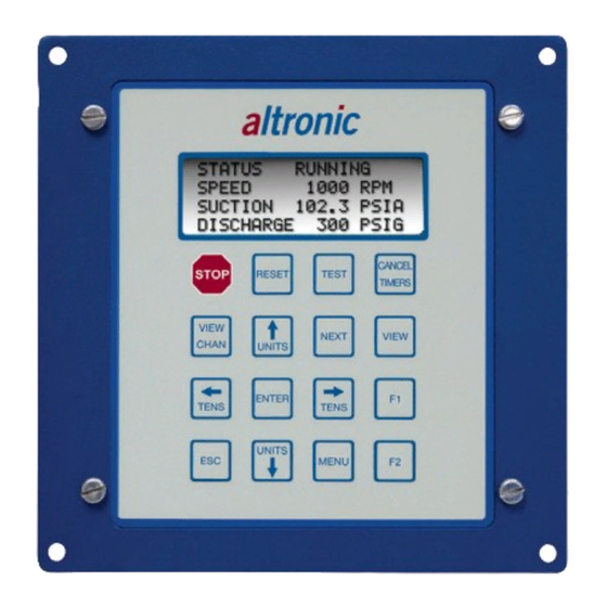
Operating Instructions DE-3000 Series Configurable Safety Shutdown and Control System with Graphing Capabilities Form DE-3000 IOI 7-17 SOME FEATURES IN THIS MANUAL ARE ONLY APPLICABLE TO DE-3000 FIRMWARE DATED 2014 OR LATER, INCLUDING: OEM Engine Control • Lube No-Flow/Lube Monitoring •... - Page 2 1-60 or 1-45 respectively. DISPLAY MODULE The Display Module serves as the user interface for the DE-3000 system. It is in a 6.5" x 6.5" panel-mounted enclosure and consists of an alphanumeric backlit LCD display, a 16-key front-mounted keypad, DB-25 D-Sub and DB-9 D-Sub connectors and five pairs of serial port indicators.
- Page 3 OUT 1 slot must be used to trip the fuel valve, and OUT 2 slot must be used to short the ignition. If 12-24Vdc is lost to the DE-3000 annunciator system, the custom Output Modules will trip the fuel valve and short the igni- tion shutdown lead.
- Page 4 PC (personal computer) or a PLC (programmable logic controller) to perform remote monitoring or control functions if desired. Terminals marked IGN IN and PU IN are used by the DE-3000 system to detect either engine rotation or ignition system firings. This input monitors changing signals such as those Seen on either the ignition shutdown lead or a magnetic pickup monitoring an engine mounted gear.
- Page 5 Module and the Display Module are electrically connected with a DB-25 male/ female cable, 693115-x series or equivalent. The operating temperature range of the Terminal Module is −31°F to +176°F (−35°C to +80°C). DE-3000 IOI 7-17 All rights reserved © ALTRONIC, LLC 2017...
- Page 6 An explosion-proof con- duit is not required. However; wires should be protected from damage by run- DE-3000 IOI 7-17 All rights reserved © ALTRONIC, LLC 2017...
- Page 7 693008-x or similar to wire transducer to the Terminal Module. An internal 5 volt sensor supply (500 mA. max.) is available to power the Altronic transducers; See wiring diagrams. If the 5 volt sensor supply exits the panel, it must be fused with a 0.5 ampere fuse.
- Page 8 SENSE ROTATION INPUT Terminals marked IGN IN and PU IN on the Power Supply Module are used by the DE-3000 system to detect either engine rotation or ignition system firings. On applications using multiple terminal board assemblies, the T+ terminal on the second terminal board (the one not directly connected to the power supply) can be used to add a second RPM value.
- Page 9 HAZARDOUS AREA OPERATION The DE-3000 system is CSA-certified for CLASS I, DIVISION 2, GROUPS C and D areas when mounted in a suitable enclosure. WARNING: SUBSTITUTION OF COMPO- NENTS MAY IMPAIR INTRINSIC SAFETY In addition, the following requirements must be met (refer to NFPA standard no. 493): AND/OR SUITABILITY FOR CLASS I, DIV.
- Page 10 DISCHARGE 200 PSIG If Multi-Start has been enabled, the DE-3000 will automatically attempt an- other AUTO START sequence if the crank disconnect RPM is not met within the user-defined time. Once the AUTO START sequence has failed, a delay timer will begin counting down before the system starts up again.
- Page 11 (if still ON) and auxiliary module remain ON for an individually programmed amount of time before turning OFF. If Multi-Start has been enabled, the DE-3000 will automatically attempt an- other OEM ENGINE CONTROL sequence if the Crank/Multi-Start disconnect RPM is not met within the user-defined time. Just like the Multi-Start for AUTO START, once the sequence has failed, the display will flash a delay timer will begin counting down before the system starts up again.
- Page 12 8971 OPERATING HOURS RUNNING PRESS TO HOURMETER / SERVICE CHANGE NUMBER MESSAGE NUMBER: ~01 ↑ HOURMETER/VIEW/CLEAR HOURS LEFT: UNITS MESSAGE NUMBER: ~01 OIL CHANGE REQUIRED HOURS LEFT: OIL CHANGE REQUIRED DE-3000 IOI 7-17 All rights reserved © ALTRONIC, LLC 2017...
- Page 13 OIL CHANGE REQUIRED There are up to eleven user programmable service messages. The desired mes- sages and service intervals are selected when programming the DE-3000 sys- tem. The service intervals can only be changed by using the terminal program and the PC. The servicemeter alert can be reset after the required service is performed by pressing the F2 key with the desired message displayed.
- Page 14 Linear/Ramp Control for suction pressure on Channel 01 Low setpoint = 5.0 PSIG at 6mA High setpoint = 20.0 PSIG at 18mA This will then create a graph as follows (page 15): DE-3000 IOI 7-17 All rights reserved © ALTRONIC, LLC 2017...
- Page 15 NEXT P: 45% I: 1s D:450m SETPOINT 1200 RPM AUTO P: 45% I: 1s D:450m AUTO RUNNING PRESS TWICE TO VIEW Calculated 1800 RPM NEXT Suction 13.3 PSIA 1800 RPM DE-3000 IOI 7-17 All rights reserved © ALTRONIC, LLC 2017...
- Page 16 In order to change the control strategy for LINEAR/RAMP control, see section 15.6. In addition to the two 4-20mA analog control loop outputs, the DE-3000 offers a pulsed digital output control option on Digital outputs #1 and #2 for use with solenoid valves or motor valves.
- Page 17 TIMERS ACTIVE home screen. ING THE UNIT. FAULT STATUS FAULT AL12 1ST FAULT STATUS FAULT AL12 CHAN 24 1ST FAULT LOW OIL PRESSURE CHAN 24 LOW OIL PRESSURE DE-3000 IOI 7-17 All rights reserved © ALTRONIC, LLC 2017...
- Page 18 STOP KEY ON THE DISPLAY MODULE. RUNNING PRESS VIEW STATUS RUNNING SPEED 1000 RPM SUCTION 102.3 PSIA DISCHARGE 200 PSIG RUNNING TERM. OUTPUT ENABLED PRESS NO OUTPUTS ENABLED VIEW TERM. OUTPUT ENABLED NO OUTPUTS ENABLED DE-3000 IOI 7-17 All rights reserved © ALTRONIC, LLC 2017...
- Page 19 PC and the terminal program. The bargraph end points are set by the low and high setpoints of the safety shutdown function. Unused channel screens will not be displayed. DE-3000 IOI 7-17 All rights reserved © ALTRONIC, LLC 2017...
- Page 20 ENGINE OIL PRESSURE TO SEE CHANNEL 21 FROM CHANNEL 20 TIMERS ACTIVE PRESS STATUS TIMERS ACTIVE ↑ ARMED STATUS TIMERS ACTIVE CHAN 20 UNITS ARMED MANIFOLD PRESSURE CHAN 20 MANIFOLD PRESSURE DE-3000 IOI 7-17 All rights reserved © ALTRONIC, LLC 2017...
- Page 21 To again view the first fault from the fault home screen, press the VIEW CHAN key. DE-3000 IOI 7-17 All rights reserved © ALTRONIC, LLC 2017...
- Page 22 102 PSIA SPEED 1000 RPM DISCHARGE 200 PSIG SUCTION 102 PSIA DISCHARGE 200 PSIG TEST SCREEN IS SHOWN WITH NO FAULTED POINTS. TEST KEY WAS PRESSED FROM THE “RUNNING” HOME SCREEN. DE-3000 IOI 7-17 All rights reserved © ALTRONIC, LLC 2017...
- Page 23 STATUS TIMERS ACTIVE home screen with the class B, C and output timers reset. RUNNING STATUS RUNNING PRESS SPEED 1000 RPM CANCEL STATUS RUNNING SUCTION 102.3 PSIA TIMERS SPEED 1000 RPM DISCHARGE 200 PSIG SUCTION 102.3 PSIA DISCHARGE 200 PSIG DE-3000 IOI 7-17 All rights reserved © ALTRONIC, LLC 2017...
- Page 24 NOTUSED ---- --- When the cool-down timer expires, the home screen status line will read FAULT AL12 with the description, COOL-DOWN SHUTDOWN. FAULT STATUS FAULT AL12 1st FAULT COOL-DOWN SHUTDOWN DE-3000 IOI 7-17 All rights reserved © ALTRONIC, LLC 2017...
- Page 25 — N/C (Normally-closed) closed in the normal run state and opens upon a fault or loss of 12-24Vdc input power — IGN (Ignition Shorting and Fuel Valve Trip Module, Altronic P/N 691124 open in the normal run state and closes upon a fault or loss of 12-24Vdc ACTIVATION DELAY TIME —...
- Page 26 EDIT PID DEAD BAND CALIBRATION RUNNING CHAN ~01 (CONTROL) LO SP 20.0 PSIA CHAN ~01 (CONTROL) HI SP 60.0 PSIA LO SP 20.0 PSIA MANIFOLD PRESSURE HI SP 60.0 PSIA MANIFOLD PRESSURE DE-3000 IOI 7-17 All rights reserved © ALTRONIC, LLC 2017...
- Page 27 ENTER. RUNNING CONTROL ~ 18.0 PSIA CYCLE TIME PROP. BAND 40 % CONTROL ~ 18.0 PSIA DEAD BAND 2.2 PSIA CYCLE TIME PROP. BAND 40 % DEAD BAND 2.2 PSIA DE-3000 IOI 7-17 All rights reserved © ALTRONIC, LLC 2017...
- Page 28 The value on the bottom shows the actual value of that channel which is being calibrated. Make sure to enter the password to modify the calibration. DE-3000 IOI 7-17 All rights reserved © ALTRONIC, LLC 2017...
- Page 29 To edit or view setpoints choose EDIT SETPOINTS. RUNNING EDIT CONTROL VALUES ~EDIT SAFETY SHUTDOWN EDIT CONTROL VALUES HOURMETER FUNCTIONS ~EDIT SAFETY SHUTDOWN VIEW FIRMWARE REV. HOURMETER FUNCTIONS VIEW FIRMWARE REV. DE-3000 IOI 7-17 All rights reserved © ALTRONIC, LLC 2017...
- Page 30 PC, both the high and low setpoints of these channels are individually selectable. A diamond next to the input class letter selects that class for the displayed channel. DE-3000 IOI 7-17 All rights reserved © ALTRONIC, LLC 2017...
- Page 31 Select MORE MENUS from the following menu. Finally, select OUT- PUT CONFIG. from the last menu. RUNNING EDIT SETPOINTS EDIT INPUT CLASS EDIT SETPOINTS EDIT GLOBAL VALUES EDIT INPUT CLASS ~MORE MENUS EDIT GLOBAL VALUES ~MORE MENUS DE-3000 IOI 7-17 All rights reserved © ALTRONIC, LLC 2017...
- Page 32 2. RUNNING THEN OUTPUT 1 ~2 PRESS PRESS DELAY TIME 3 SEC NEXT OUTPUT 1 ~2 ENTER ©IGN DELAY TIME 3 SEC ©IGN DE-3000 IOI 7-17 All rights reserved © ALTRONIC, LLC 2017...
- Page 33 Select MORE MENUS from the following menu. Finally, select EDIT TIME AND DATE from the last menu. RUNNING OUTPUT CONFIG. ~EDIT TIME AND DATE COMMUNICATIONS OUTPUT CONFIG. TO PREVIOUS MENU ~EDIT TIME AND DATE COMMUNICATIONS TO PREVIOUS MENU DE-3000 IOI 7-17 All rights reserved © ALTRONIC, LLC 2017...
- Page 34 Use the NEXT key to select node, port 1 or port 3; then use the UP or DOWN arrow keys to change the node number from 1 to 99 and port 1 and port 3 from ASCII to MODBUS. Press ENTER to save selection. DE-3000 IOI 7-17 All rights reserved © ALTRONIC, LLC 2017...
- Page 35 ~VIEW FIRMWARE REV. RUNNING DE-3000 DISPLAY: 05/12/12 DE-3000 TERMINAL: 04/02/12 DISPLAY: 05/12/12 SPECIAL: 000001 TERMINAL: 04/02/12 SPECIAL: 000001 NOTE: SPECIAL FIRMWARE VERSIONS WILL DISPLAY FILE REFERENCE NUM- BER ON BOTTOM LINE. DE-3000 IOI 7-17 All rights reserved © ALTRONIC, LLC 2017...
- Page 36 16.0 VIEWING THE TIME AND DATE OF THE FIRST FAULT 16.1 The DE-3000 controller system “stamps” the time and date occurrence of the first fault. To view the time and date of the first fault, press the F2 key after a fault occurs but before reset is initiated.
- Page 37 18.5 The DE-3000 system uses a simple ASCII command to read the data collected. The ASCII command must be transmitted to the controller by the PC or PLC before it can respond. The command is shown below. The hexadecimal values for the characters are shown only for those using low level (assembly language) decoding and will not appear on the communications terminal screen.
- Page 38 18.9 The most current data can be read remotely by sending the following ASCII com- mand: >(01 DL 000) 18.10 The DE-3000 system can be reset or stopped remotely by sending a serial com- mand string. REMOTE RESET >(01 AUTO) REMOTE STOP >(01 STOP)
- Page 39 NN = node number, 20 = KP function code, 88 = number of bytes to follow, CR = Carriage Return, LF = Linefeed, 4 20-byte ASCII blocks that is the display, CRC CRC = two byte Modbus RTU CRC DE-3000 IOI 7-17 All rights reserved © ALTRONIC, LLC 2017...
- Page 40 19.0 AUTOMATIC CALL OUT USING AN EXTERNAL MODEM 19.1 The DE-3000 controller system can perform an automatic call out upon a fault condition. When a fault occurs, the system will dial up to four preprogrammed phone numbers stored in an external modem, negotiate communications and send the first fault data log report message (the 999 command) to the Altronic monitor program on a PC or to a customer supplied device.
- Page 41 When the pressure goes above 25.0 the ALARMED message reads: RUNNING STATUS RUNNING ALARMED CHAN 12 26.3 PSIG STATUS RUNNING MANIFOLD AIR PRESS ALARMED CHAN 12 26.3 PSIG MANIFOLD AIR PRESS DE-3000 IOI 7-17 All rights reserved © ALTRONIC, LLC 2017...
- Page 42 2nd line resumes displaying ARMED. 21.0 INTEGRATED TIMER OUTPUTS 21.1 On 2014 and later versions of the DE-3000, digital outputs #5 and #13 may be configured in the terminal program to be used as integrated timers. When configured for this function, the digital outputs turn ON at the engine start and remain ON until a specified amount of time has passed since a stop or fault.
- Page 43 • terminals FV1 and FV2 for the fuel valve and IGN+ and IGN- for the ignition shutdown lead. Make sure that Altronic output module 691124 is in power supply output slots • OUT 1 and OUT 2. 22.8 The time and date, after being set (see section 15.13), are not correct after removing and reapplying the input power: The real time clock/RAM module (U10) needs replaced.
- Page 44 AUTO START command is received returning the system to STATE 0. If the DE-3000 is set up for Multi- Start, then a delay timer will begin counting down before another start attempt is automatically triggered.
- Page 45 CONTROL: Out 1 for Driven Equipment Ready (DER), Out 2 for Start/Run Signal, Out 3 Auxiliary if necessary, Out 4 for Pre/Post Lube. OEM ENGINE CONTROL begins its sequence when an auto start command is sent to the DE-3000. The various programmable timers for each module on the power supply board output are shown below.
- Page 46 Start/Run Signal and the Auxiliary output begin counting down. DER remains ON from the time the auto start signal is sent to the DE-3000 until a manual stop or fault occurs. All class A setpoints are monitored and class B and C timers begin once the auto start signal is received.
- Page 47 25.6 When programming the DE-3000 system, the basic relationship of the Primary Control Inputs (A1, A2, S1), Primary Control Outputs (AO1 and AO2), and Out- put Actuators needs to be defined.
- Page 48 DE-3000. Under the CALIBRATION SETPOINT section is a box that reads CURRENT • DATA. This is the actual information being displayed on the DE-3000 Display. On the Terminal Board connect a voltmeter between the (+) and (-) transducer •...
- Page 49 27.2 PASSWORD FOR THE NEXT KEY (PID PARAMETERS) The DE-3000 contains a numerical password, when correct, which allows the user to modify PID parameters. The range of the password may be any number between 0 and 999. When the NEXT key is pressed, the screen below appears.
- Page 50 NEXT to view and modify PID parameters. Use the UP, UP/TENS, DOWN, WISHING PASSWORD PROTECTION, DOWN/TENS keys to modify the new password value and press ENTER to save LEAVE THE PASSWORD AT ‘1’. the new password. DE-3000 IOI 7-17 All rights reserved © ALTRONIC, LLC 2017...
- Page 51 When asked if you would like it to make changes to the computer, click ‘Yes’. This file can be found at: C:\Altronic LLC\Altronic DE-3000 Terminal Program Vx.x\CDMxxxxx_SETUP 28.3 When the FTDI driver package opens, the following screen will appear. Click ‘Extract’.
- Page 52 The device is now able to connect to the PC and be configured using the terminal program. 28.6 Click “Finish” to complete the installation. DE-3000 IOI 7-17 All rights reserved © ALTRONIC, LLC 2017...
- Page 53 Universal Serial Bus Controllers. 29.4 Windows XP does not have this check box, so driver files and OEM INF and PNF files must be removed manually or by using a custom application. DE-3000 IOI 7-17 All rights reserved © ALTRONIC, LLC 2017...
- Page 54 When the program first runs, you must input a user name along with the selection of the PC serial or USB port to which the DE-3000 will connect for programming. All screens have a status bar at the bottom that will let the user know the current status of each operation.
- Page 55 1.X configuration into an equivalent 2.X one. Once it has been converted, it is possible to utilize any new features included only in the 2.X version and then save the file as a .PG7. THE DE-3000 STILL CAN ONLY BE PROGRAMMED THROUGH THE 2.X TERMINAL PRO- GRAM IF ALL TERMINAL AND DISPLAY BOARD FIRMWARE FOR THE DEVICE IS DATED 2014 OR LATER.
- Page 56 (Version 2.X). Doing so sets up the sensor type on the screen and al lows a maximum time between pulses to be entered. DE-3000 IOI 7-17 All rights reserved © ALTRONIC, LLC 2017...
- Page 57 C. Cascade RPM/LOAD Control - configure A02 for Cascade Control D. Linear/Ramp Control - (Version 2.X only) configure A02 for Linear/ Ramp Control. The DE-3000 will create a linear relationship between the value of Channel 1 and the output current. It is up to the user to map an accurate RPM value to the min and max output limit.
- Page 58 DE-3x00 calls the PC where the host mode is enabled, the results will be displayed in this text window. 30.12 EXIT This ends program execution and returns the user to the Windows™ operating system. DE-3000 IOI 7-17 All rights reserved © ALTRONIC, LLC 2017...
- Page 59 (I/P). ANALOG INPUT An input which accepts voltage signals between 0 and 5 volts. These signals are converted by the DE-3000 to en- gineering units and compared by the microprocessor to user programmed safety shutdown and control setpoints.
- Page 60 The engine speed output to the governor will be held at the idle RPM value during the warmup delay. DE-3000 IOI 7-17 All rights reserved © ALTRONIC, LLC 2017...
- Page 61 The ASCII characters of what is contained on the display of the 40069 DE-3000. The upper part of the register displays the first character followed by the low part of the register as the next character. This may be used for MMI/MIDAS applications.
- Page 62 25.0 SELECTING A CONTROL STRATEGY 26.0 CALIBRATION OF TRANSDUCERS 27.0 PASSWORD PROTECTION 28.0 USB VIRTUAL COM PORT DRIVER INSTALLATION 29.0 USB VIRTUAL COM PORT DRIVER UNINSTALLATION 30.0 PROGRAMMING INSTRUCTIONSDRAWINGS SECTION: DE-3000 IOI 7-17 All rights reserved © ALTRONIC, LLC 2017...
- Page 63 FIG. 1 AUTOSTART SEQUENCE OF OPERATION FIG. 2 DE-3000 SYSTEM DIAGRAM FIG. 3 DE-3000 TERMINAL MODULE AND POWER SUPPLY MODULE FIG. 4 WIRING DIAGRAM: GENERAL HOOK-UP FIG. 5 WIRING DIAGRAM: PERSONAL COMPUTER FIG. 6 WIRING DIAGRAM: SENSOR AND TRANSDUCER INPUTS FIG.
- Page 64 FIG. 1 AUTOSTART SEQUENCE OF OPERATION DE-3000 IOI 7-17 All rights reserved © ALTRONIC, LLC 2017...
- Page 65 FIG. 2 DE-3000 SYSTEM DIAGRAM DE-3000 IOI 7-17 All rights reserved © ALTRONIC, LLC 2017...
- Page 66 FIG. 3 DE-3000 TERMINAL MODULE AND POWER SUPPLY MODULE DE-3000 IOI 7-17 All rights reserved © ALTRONIC, LLC 2017...
- Page 67 FIG. 4 WIRING DIAGRAM: GENERAL HOOK-UP DE-3000 IOI 7-17 All rights reserved © ALTRONIC, LLC 2017...
- Page 68 FIG. 5 WIRING DIAGRAM: PERSONAL COMPUTER DE-3000 IOI 7-17 All rights reserved © ALTRONIC, LLC 2017...
- Page 69 FIG. 6 WIRING DIAGRAM: SENSOR AND TRANSDUCER INPUTS DE-3000 IOI 7-17 All rights reserved © ALTRONIC, LLC 2017...
- Page 70 FIG. 7 WIRING DIAGRAM: CURRENT LOOP OUTPUTS DE-3000 IOI 7-17 All rights reserved © ALTRONIC, LLC 2017...
- Page 71 FIG. 8 WIRING DIAGRAM: DIGITAL OUTPUT SWITCHES DE-3000 IOI 7-17 All rights reserved © ALTRONIC, LLC 2017...
- Page 72 FIG. 9 WIRING DIAGRAM: POWER SUPPLY MODULE DE-3000 IOI 7-17 All rights reserved © ALTRONIC, LLC 2017...
- Page 73 FIG. 10 POWER SUPPLY LED AND OUTPUT MODULE LOCATIONS DE-3000 IOI 7-17 All rights reserved © ALTRONIC, LLC 2017...
- Page 74 FIG. 11 WIRING DIAGRAM: TACHOMETER INPUT DE-3000 IOI 7-17 All rights reserved © ALTRONIC, LLC 2017...
- Page 75 FIG. 12 WIRING DIAGRAM: RS-485 COMMUNICATIONS DE-3000 IOI 7-17 All rights reserved © ALTRONIC, LLC 2017...
- Page 76 FIG. 13 DE-3000 DISPLAY – CONTRAST ADJUSTMENT (CLASSIC DISPLAY ONLY) DE-3000 IOI 7-17 All rights reserved © ALTRONIC, LLC 2017...
- Page 77 CLASS I, DIVISION 2, GROUPS C and D areas when mounted in a suitable enclosure. The DE-3000 system may also be used in a DIVISION 1 hazardous area if it incorporates only the devices shown in the drawing at right, and is installed as shown.
Need help?
Do you have a question about the DE-3000 and is the answer not in the manual?
Questions and answers