Table of Contents
Advertisement
Advertisement
Table of Contents

Related Manuals for Motorline ROSSO EVO


Summary of Contents for Motorline ROSSO EVO
- Page 1 ROSSO EVO User’s and Installer’s manual v1.0 REV. 01/2014...
-
Page 2: Table Of Contents
| pag 12.A 07. DIAGNOSIS connecting engine to 24V battery | pag 12.B 08. TROUBLESHOOTING instructions for final consumers | pag 13.A instructions for technical personnel | pag 13.A 09. CENTRAL CONNECTIONS ROSSO EVO central | pag 14.A 01.A 01.B... -
Page 3: Package
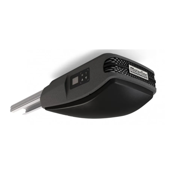
Radio frequency 433,92Hz 433,92Hz 433,92Hz MX4SP Plates to fix ROSSO EVO transmitters on gate The automatism ROSSO EVO dimensions are as follows: Metal plates to fix Motor 359mm and Rail Metal Stopper Plate to fix rail to lintel Metal Plate to fix rail to... -
Page 4: Manual Brake Release | Pag 03.A
THE AUTOMATISM MANUAL BRAKE RELEASE REMOVING TOP COVER The ROSSO EVO unlocking system is very simple and practical to use. To do so just pull the lever down (following figure). To block simply pull the lever to the original position. -
Page 5: Changing Courtesy Leds | Pag 04.A
INSTALLATION CHANGING COURTESY LEDS INFORMATION PRE-INSTALLATION For a correct operation of ROSSO EVO, you must take into account the following parameters before the installation: Read all steps on this manual at least once in order to get acquainted with the installation and configuration process. - Page 6 INSTALLATION INSTALLATION FIXING THE MOTOR IN RAILS AUTOMATISM INSTALLATION With standard rails, you can only automate doors with maximum height of 2400mm. 125-175mm 100-150mm 01 - Attach the rail’s support plate to the lintel, as visible in the left image. In the right image if can be seen the distance to keep between the gate rail and support plate’s upper part (125-175mm).
- Page 7 INSTALLATION INSTALLATION AUTOMATISM INSTALLATION AUTOMATISM INSTALLATION 03 - Place celling rail ‘s fixation plate roughly halfway through the steel rail as visible in 05 - After rising the rail and mark the holes, you should fix the plate with screws. the pictures above.
-
Page 8: Installation Map | Pag 07.A
INSTALLATION INSTALLATION MAP LEGEND: ROSSO EVO Motor Steel rail Rail to ceilling’s/struture’s fixation plate Bracket for structure fixing Fast rail to ceilling’s/struture’s fixation plate Trolley with unlocking system Rail to lintel’s fixation plate Connection arm between trolley and gate Fixation rod to the gate Shaft and sectional door springs 07.A... -
Page 9: Programming
PROGRAMMING PROGRAMMING LEGEND MENU FUNCTIONS ↓ Legend The control board has a main menu which allows access to all the di erent settings of the automatism. Display Main Menu Programming opening and closing courses Programming the automatism force level Programming transmmiters Enable / disable safety photocells Programming the self-closing feature Down... - Page 10 PROGRAMMING PROGRAMMING MENU FUNCTIONS MENU FUNCTIONS Programming the self closing feature Programming the automatism force level Press the M button for seconds to enter the programming menu. Press the M key for seconds to enter the programming menu. The display will show P and press keys repeatedly until it shows P .
- Page 11 PROGRAMMING PROGRAMMING MENU FUNCTIONS MENU FUNCTIONS Programming maintenance warnings Counting maneuvers Press the M key for seconds to enter the programming menu. Press the M key for seconds to enter the programming menu. The display will show P and press keys repeatedly until it shows P .
-
Page 12: Post-Installation
With the door completely open, push the stopper untill it touches the trolley (2). Fasten the two screws to hold the stopper in that exact position (3). The control board has a maximum capacity of 30 transmitters and only accepts Motorline Rolling Code transmitters! 11.A 11.B... -
Page 13: Stretch Rail Chain | Pag 12.A
POST-INSTALLATION DIAGNOSIS STRETCH RAIL’S CHAIN CONNECT ENGINE TO 24V BATTERY For a correct automatism function, the chain has to be very well adjusted. In case of automatism failure or malfunction, you must detect the fail component For that, you just need to tighten or loosen the shadowed nut in the above picture with (motor or central). -
Page 14: Troubleshooting
Pull it remove it and send it to the gate. 24V battery to find the malfunc- out and send it to the Motorline Motorline technical services for tion (see page 12.B) technical services for diagnosis;... -
Page 15: Central Connections
CENTRAL CONNECTIONS ROSSO EVO CONTROL BOARD Pedestrian Door Pushbutton / Photocells MF1 Lightbulb External Receiver Outdoor Antenna Key Selector 12/24v DV 12/24V 12/24V CH1-a (or) CH1-b CH2-a W máx CH2-b Courtesy LEDs CON * 230V Battery 12/24V Receiver Power Encoder...
Need help?
Do you have a question about the ROSSO EVO and is the answer not in the manual?
Questions and answers
The display shows "0" only, and I don't know how to reset to stand-by so that I can start programming the unit. The "0" is there all the time. Is there a way to reset to stand-by?
Press the "M" key once to save the option. The control board will then exit to standby mode (--) and the configuration will be complete.
This answer is automatically generated