
Related Manuals for Vmac G300003


Summary of Contents for Vmac G300003
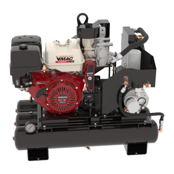
- Page 1 Gas Engine Driven 30 CFM Air Compressor Installation, Owner’s and Service Manual G300003...
-
Page 3: Table Of Contents
System Adjustment for Large Receiver Tanks ........68 Electrical Components and Testing ............69 Component Repair / Replacement ............72 Illustrated Parts List ................82 Warranty Registration ................89 Service Records ..................91 VMAC – Vehicle Mounted Air Compressors VMAC Technical Support: 1-888-241-2289 VMAC Knowledge Base: www.kb.vmacair.com... -
Page 4: Important Information
Copyright © 2017 VMAC Global Technology Inc. All Rights Reserved. These materials are provided by VMAC for informational purposes only, without representation or warranty of any kind, and VMAC shall not be liable for errors or omissions with respect to the materials. The only warranties for... -
Page 5: Safety
Information is constantly changing with the addition of new models, assemblies, service techniques and running OEM changes. If a discrepancy is found in this manual, contact VMAC prior to initiating or proceeding with installation, service or repair. Current information may clarify the issue. Any person with knowledge of such discrepancies, who proceeds to perform service and repair assumes all risks. -
Page 6: Warranty
1 October, 2015. Warranty Registration The VMAC warranty registration form is located near the back of this manual. This warranty registration form must be completed and sent to VMAC at the time of installation for any subsequent warranty claim to be considered valid. -
Page 7: Safety Precautions
Proper service and repair are important to the safety of the service technician and the safe, reliable operation of the equipment. Always use genuine VMAC and/or Honda replacement parts. The procedures described in this service manual are effective methods of service and repair. -
Page 8: Personal Safety
• Follow all safety precautions when jump starting or charging a battery. • Never attempt to jump start a frozen battery. • Never overcharge a battery. VMAC – Vehicle Mounted Air Compressors VMAC Technical Support: 1-888-241-2289 VMAC Knowledge Base: www.kb.vmacair.com... - Page 9 • Do not operate the compressor without guards in place. If the guards are damaged or missing, replace them before operating the equipment. VMAC – Vehicle Mounted Air Compressors VMAC Technical Support: 1-888-241-2289 VMAC Knowledge Base: www.kb.vmacair.com...
- Page 10 Never adjust or attempt to make any repairs to the compressor system while the engine is running. Components and hoses under pressure could fail and cause serious injury or death. VMAC – Vehicle Mounted Air Compressors VMAC Technical Support: 1-888-241-2289 VMAC Knowledge Base: www.kb.vmacair.com...
-
Page 11: General Information
Please contact VMAC for replacement hoses and further information. Ordering Parts To order parts, contact a VMAC dealer. The dealer will ask for the VMAC serial number, part number, description and quantity. Locate the nearest dealer online at www.vmacair.com/dealer-locator or call 1-877-912-6605. -
Page 12: Safety Features
The engine will not be able to be restarted until the system has cooled and the temperature switch has closed. VMAC – Vehicle Mounted Air Compressors VMAC Technical Support: 1-888-241-2289 VMAC Knowledge Base: www.kb.vmacair.com... -
Page 13: Operating Principles
Operating Principles Air Compression The Gas Engine Driven 30 CFM Air Compressor uses a VMAC designed and manufactured flooded lobe, rotary screw compressor. The oil filled compressor housing contains 2 rotors. Compression occurs when air (at normal atmospheric pressure) enters a chamber where it is trapped between meshing rotor lobes. -
Page 14: Spark Arrester
Filtration VMAC rotary screw compressors are designed and machined to exacting tolerances. Foreign particles entering the compressor can damage system components such as seals, bearings, rotors, as well as the inside of the housing, resulting in performance losses and reduced system life. -
Page 15: Extreme Climates And Elevation
Cold Environment Operation The Gas Engine Driven 30 CFM Air Compressor system is not designed or recommended for use in cold climates (below 0 °C / 32 °F) unless equipped with a VMAC cold climate kit (P/N: A500044). Cold Environment Recommendations Ensure the following conditions are met before starting the compressor: •... -
Page 16: High Altitude Operation
For engine oil recommendations in temperatures above 40 °C (104 °F) refer to the Honda GX390 Owner’s Manual supplied with the system (VMAC P/N: 1901066). Failure to follow the information supplied in the Honda Owner’s Manual may result in poor engine performance or engine damage. -
Page 17: System Overview
To order parts, contact a local dealer or contact the sales team. Dealer locator: http://www.vmacair.com/dealer-locator/ Toll free: 1-(800) 738-8622 Email: sales@vmacair.com. For technical support visit VMAC’s Knowledge Base or contact the technical support team. Knowledge Base: http://kb.vmacair.com/ Toll free: 1-(888) 241- 2289 Email: tech@vmacair.com VMAC –... - Page 18 Unloader valve • Discharge valve WHASP Tank Compressor Engine Key start Unloader Discharge Battery Hour meter valve valve Figure 4 – System overview (Shroud removed for clarity) VMAC – Vehicle Mounted Air Compressors VMAC Technical Support: 1-888-241-2289 VMAC Knowledge Base: www.kb.vmacair.com...
- Page 19 System Components (Back) • Lifting eye • Belt shroud • Fuel fill • Exhaust shroud Lifting eye Fuel fill Exhaust shroud Belt shroud Figure 5 – System overview VMAC – Vehicle Mounted Air Compressors VMAC Technical Support: 1-888-241-2289 VMAC Knowledge Base: www.kb.vmacair.com...
-
Page 20: System Controls And Features
The electric fan on the WHASP Tank can turn on at any time. This is normal operation. Key start Recoil Choke pull start Fuel shut Unloader valve Hour meter Figure 6 – System controls overview VMAC – Vehicle Mounted Air Compressors VMAC Technical Support: 1-888-241-2289 VMAC Knowledge Base: www.kb.vmacair.com... -
Page 21: Installation Requirements
The belt guard is accessible and can be removed for service. • The engine oil drain, oil fill, fuel fill, and air filter are easily accessible for service (the VMAC Remote Oil Drain accessory can help facilitate servicing the engine and compressor oil P/N: A500043). •... -
Page 22: Ventilation Requirements
Exhaust and waste heat from the Gas Engine Driven 30 CFM Air Compressor system must be vented away from the system to prevent the gas engine from ingesting its exhaust and stalling. VMAC – Vehicle Mounted Air Compressors VMAC Technical Support: 1-888-241-2289 VMAC Knowledge Base: www.kb.vmacair.com... -
Page 23: Mounting Locations
Ensure adequate ventilation is provided for cooling and to evacuate the exhaust. If mounting in an enclosure, VMAC strongly recommends mounting the unit on a pullout drawer and extending the drawer any time the unit is run. -
Page 24: Mounting The Compressor
Air Compressor. Place the unit in its intended location and check for clearances to any other objects (Figure 10). All dimensions are in inches. 34.0 23.9 22.0 25.0 20.7 19.1 Figure 10 – External dimensions VMAC – Vehicle Mounted Air Compressors VMAC Technical Support: 1-888-241-2289 VMAC Knowledge Base: www.kb.vmacair.com... - Page 25 Connect the downstream plumbing to the ball valve outlet. All dimensions are in inches. Ø.43 (6x) 12.0 12.0 18.0 0.56 Figure 11 – Base plate mounting configuration VMAC – Vehicle Mounted Air Compressors VMAC Technical Support: 1-888-241-2289 VMAC Knowledge Base: www.kb.vmacair.com...
-
Page 26: Before Starting The Gas Engine Driven 30 Cfm Air Compressor
Ensure the following has been completed before operating the Gas Engine Driven 30 CFM Air Compressor: Check the compressor oil level and condition (Page 42). New VMAC oil is clear and may be difficult to see in the sight glass. Inspect the blowdown muffler (Page 43). -
Page 27: Starting And Stopping The Engine
3) Actuate the unloader valve by pulling out the handle (Figure 13). The unloader valve should be opened to reduce the load on the engine during warm up. Unloader valve Figure 13 – Unloader valve VMAC – Vehicle Mounted Air Compressors VMAC Technical Support: 1-888-241-2289 VMAC Knowledge Base: www.kb.vmacair.com... - Page 28 While the unloader valve is actuated the system will only build to 40 psi. Once the engine has warmed up, close the unloader valve to allow the system to build to full system pressure. VMAC – Vehicle Mounted Air Compressors VMAC Technical Support: 1-888-241-2289 VMAC Knowledge Base: www.kb.vmacair.com...
- Page 29 7) Actuate the unloader valve by pulling out the handle (Figure 18). The unloader valve should be opened to reduce the load on the engine during warm up. Unloader valve Figure 18 – Unloader valve VMAC – Vehicle Mounted Air Compressors VMAC Technical Support: 1-888-241-2289 VMAC Knowledge Base: www.kb.vmacair.com...
- Page 30 While the unloader valve is actuated the system will only build to 40 psi. Once the engine has warmed up, close the unloader valve to allow the system to build to full system pressure. VMAC – Vehicle Mounted Air Compressors VMAC Technical Support: 1-888-241-2289 VMAC Knowledge Base: www.kb.vmacair.com...
- Page 31 Failure to do this may allow fuel to overfill the carburetor float bowl and flow into the engine’s cylinder and/or crank case causing the engine to hydraulically lock. VMAC – Vehicle Mounted Air Compressors VMAC Technical Support: 1-888-241-2289 VMAC Knowledge Base: www.kb.vmacair.com...
-
Page 32: Recommended Accessories
For information on installing an air receiver tank see the “Air Receiver Tank” section of this manual on page 31. Air receiver tanks are available for purchase through VMAC. See the “Accessory Product” section of this manual on page 34 for more information. -
Page 33: Air Receiver Tank
The VMAC compressor system automatically depressurizes when it is shut- down. The VMAC WHASP Tank has a one-way check valve installed from the factory which prevents the compressed air and any moisture in receiver tank from traveling back into the WHASP Tank. -
Page 34: Setup, Performance Testing And Adjustments
This system has been adjusted at the factory for general operation. System operation can be tested using the tools that will be operated by the system or by using the VMAC Test Tool (A700052) with the 30 cfm (1/8 in) orifice in the outlet to simulate tool use (Figure 24). -
Page 35: Engine Rpm Adjustment
The engine “low idle” and “high idle” screws are set at the factory and do not require adjustment. The throttle actuator will automatically raise and lower the engine speed dependant upon air demand. VMAC – Vehicle Mounted Air Compressors VMAC Technical Support: 1-888-241-2289 VMAC Knowledge Base: www.kb.vmacair.com... -
Page 36: Accessory Products From Vmac
Max pressure: up to 150 psi • Dimensions: 35.0 in (88.9 cm) L x 20.5 in (52.0 cm) W x 8.4 in (21.3 cm) H • Weight: 80 lb (36 kg) VMAC – Vehicle Mounted Air Compressors VMAC Technical Support: 1-888-241-2289 VMAC Knowledge Base: www.kb.vmacair.com... - Page 37 Air receiver tanks are used for lowering compressor duty cycle and removing water from compressed air; recommended for optimum operation of all VMAC Gas Driven, Diesel Driven, Hydraulic, and UNDERHOOD30 air compressors. Manufactured to FMVSS 121 standard; includes fittings, 160 psi pressure relief valve, and tank drain.
- Page 38 Port size: 3/4 in NPT inlet and outlet Compressor Service Kits 200 Hour or 6 Month Service Kit - Part number: A700219 Includes 4 L VMAC high performance compressor oil, oil filter, air filter, and next service due decal. 400 Hour or 1-Year Service Kit -...
-
Page 39: General Maintenance Information
Routine Maintenance In order to maintain the VMAC warranty, VMAC’s maintenance schedule must be followed. Only genuine original VMAC replacement parts can be used to maintain the system. The compressor system does not contain reed valves or other easily fouled, fatigue prone components. -
Page 40: Maintenance And Repair Safety
Use only genuine VMAC replacement parts to maintain the system. Genuine VMAC replacement parts are designed to work with the high pressure and heat generated by the compressor. - Page 41 Remove the shroud, there are 3 fasteners that secure it to the base and WHASP Tank (Figure 26). Remove fasteners Figure 26 – Remove shroud VMAC – Vehicle Mounted Air Compressors VMAC Technical Support: 1-888-241-2289 VMAC Knowledge Base: www.kb.vmacair.com...
- Page 42 Figure 27 – Negative battery terminal Disconnect the spark plug wire (Figure 28). Disconnect spark plug wire Figure 28 – Spark plug wire VMAC – Vehicle Mounted Air Compressors VMAC Technical Support: 1-888-241-2289 VMAC Knowledge Base: www.kb.vmacair.com...
-
Page 43: Maintenance Schedule
Maintenance Schedule In order to maintain the warranty on the Gas Engine Driven 30 CFM Air Compressor, use only genuine VMAC and/or Honda replacement parts to service the system. Refer to the Honda Owner’s Manual for the engine maintenance schedule and instructions. -
Page 44: Regular Inspection Instructions
“MAX” arrow. Replace the fill cap and tighten securely. Oil fill cap Sight glass Oil drain Figure 29 – Inspecting the oil VMAC – Vehicle Mounted Air Compressors VMAC Technical Support: 1-888-241-2289 VMAC Knowledge Base: www.kb.vmacair.com... - Page 45 WHASP Tank. Blowdown should be completed in approximately 20 seconds. If the muffler is showing signs of blockage, contact a local VMAC dealer for a replacement. A replacement blowdown muffler is included with the VMAC 400 hour service kit.
- Page 46 If the pressure relief valve is showing loss of functionality, contact a local VMAC dealer for a replacement. A replacement pressure relief valve is included with the VMAC 400 hour service kit. 200 psi relief valve Figure 31 – Pressure relief valve (Shroud removed for clarity) VMAC –...
- Page 47 Replace the cover and secure it with the filter cover retainer knob. Do not overtighten. Filter plate “step” Figure 32 – Compressor air filter and cover VMAC – Vehicle Mounted Air Compressors VMAC Technical Support: 1-888-241-2289 VMAC Knowledge Base: www.kb.vmacair.com...
- Page 48 Figure 33 – Inspecting the drive belt Description Part Number Belt (Gates part number K040438) 1620365 Tensioner (Ford part number 7C3Z-6B209-D) 3300036 Table 4 – Belt part numbers and tension VMAC – Vehicle Mounted Air Compressors VMAC Technical Support: 1-888-241-2289 VMAC Knowledge Base: www.kb.vmacair.com...
- Page 49 The scavenge, pressure control and throttle control tubes are made of Polytetrafluoroethylene (PTFE) and are within specification to work with VMAC compressor oil and to withstand the high pressure and operating temperatures generated by the compressor. Standard air brake hose is not a suitable replacement.
-
Page 50: 200 Hour / 6 Month Service
Install and tighten the oil drain plug. Remove the oil filter (Figure 35). Oil filter Oil drain plug Figure 35 – Compressor oil filter VMAC – Vehicle Mounted Air Compressors VMAC Technical Support: 1-888-241-2289 VMAC Knowledge Base: www.kb.vmacair.com... - Page 51 Remove the filler cap on the WHASP Tank. Fill the WHASP Tank with VMAC compressor oil until is reaches the “MAX” mark. The air compressor system holds approximately 4 L (1 USG) of oil (Figure 37). Figure 37 – Compressor oil fill VMAC –...
- Page 52 Once the system has sat for 5 minutes, check the oil level through the sight glass. The level must be between the “MIN” and “MAX” level indicators. Verify there are no oil leaks. VMAC – Vehicle Mounted Air Compressors VMAC Technical Support: 1-888-241-2289 VMAC Knowledge Base: www.kb.vmacair.com...
-
Page 53: 400 Hour / 1 Year Service
Install and tighten the oil drain plug. Remove the oil filter (Figure 38). Oil filter Oil drain plug Figure 38 – Compressor oil filter VMAC – Vehicle Mounted Air Compressors VMAC Technical Support: 1-888-241-2289 VMAC Knowledge Base: www.kb.vmacair.com... - Page 54 Remove the filler cap on the WHASP Tank. Fill the WHASP Tank with VMAC compressor oil until is reaches the “MAX” mark. The air compressor system holds approximately 4 L (1 USG) of oil (Figure 40). Figure 40 – Compressor oil fill VMAC –...
- Page 55 Once the system has sat for 5 minutes, check the oil level through the sight glass. The level must be between the “MIN” and “MAX” level indicators. Verify there are no oil leaks. VMAC – Vehicle Mounted Air Compressors VMAC Technical Support: 1-888-241-2289 VMAC Knowledge Base: www.kb.vmacair.com...
-
Page 56: Engine Maintenance And Warranty Information
Engine Maintenance and Warranty Information The VMAC Gas Engine Driven 30 CFM Air Compressor uses the Honda GX390 engine. For engine service intervals and instructions, refer to the Honda Owner’s Manual supplied with the system (VMAC P/N: 1901066). Failure to follow the instructions in the Honda Owner’s Manual could result in poor engine performance, engine damage and may void the Honda engine warranty. -
Page 57: Diagnostics And Trouble Shooting
Air Compressor from all downstream (customer supplied) equipment. If the Gas Engine Driven 30 CFM Air Compressor is still within the warranty period, contact VMAC prior to commencing any diagnostics or repairs. Problem diagnosis should follow sound, recognized practices. Quick and accurate diagnosis of problems should involve the following: •... - Page 58 Add oil to engine. Spark plug gap. Replace spark plug. Spark arrester Clean or replace the spark clogged. arrester. See enclosure mounting Mounted in enclosure. parameters on p. 21. VMAC – Vehicle Mounted Air Compressors VMAC Technical Support: 1-888-241-2289 VMAC Knowledge Base: www.kb.vmacair.com...
- Page 59 Fuel shut off lever left on Remove spark plug. Use recoil during transport, fuel starter to drain cylinder. Change flooded crank case and oil and filter. cylinder. VMAC – Vehicle Mounted Air Compressors VMAC Technical Support: 1-888-241-2289 VMAC Knowledge Base: www.kb.vmacair.com...
- Page 60 Compressor oil overfilled. Oil comes out of the level ground. blowdown muffler. Faulty blowdown shuttle Replace blowdown shuttle valve. valve. Replace blowdown valve Blowdown valve failure. assembly. VMAC – Vehicle Mounted Air Compressors VMAC Technical Support: 1-888-241-2289 VMAC Knowledge Base: www.kb.vmacair.com...
- Page 61 CORRECTIVE ACTION Air leaking from small This is normal and as per hole in inlet valve None required. design. regulator cap. Table 5 – Trouble shooting table VMAC – Vehicle Mounted Air Compressors VMAC Technical Support: 1-888-241-2289 VMAC Knowledge Base: www.kb.vmacair.com...
- Page 62 Diagnostic Tools VMAC Air Test Tool (P/N: A700052) To properly diagnose VMAC’s Gas Engine Driven 30 CFM Air Compressor, a VMAC Air Test Tool (P/N: A700052), or equivalent, is required. For testing and diagnosis, install the 30 cfm (1/8 in) orifice.
-
Page 63: Compressor Regulation And Throttle Actuator Testing
Compressor Regulation and Throttle Actuator Testing Throttle Control VMAC configures the Honda engine throttle to be wide open in its neutral state (0 psi). Engine rpm is controlled via the throttle actuator which is operated by air pressure from the unloader valve. - Page 64 1/4 in PTFE union (Figure 47). Unloader valve Discharge valve Throttle actuator 1/4 in PTFE union Figure 47 – Throttle actuator tube VMAC – Vehicle Mounted Air Compressors VMAC Technical Support: 1-888-241-2289 VMAC Knowledge Base: www.kb.vmacair.com...
- Page 65 1/4 in compressor fitting and air bleed muffler Discharge valve Figure 49 – 1/4 in Pressure control tube (Key switch module removed for clarity) VMAC – Vehicle Mounted Air Compressors VMAC Technical Support: 1-888-241-2289 VMAC Knowledge Base: www.kb.vmacair.com...
- Page 66 3/16 in compressor fitting at inlet regulator Discharge valve 1/4 in PTFE pressure control tube Figure 50 – 3/16 in Pressure control tube (Belt guard removed for clarity) VMAC – Vehicle Mounted Air Compressors VMAC Technical Support: 1-888-241-2289 VMAC Knowledge Base: www.kb.vmacair.com...
- Page 67 Unloader valve Discharge valve VMAC Air Test 1/4 in PTFE union PTFE Test Tool Tool (A700052) Figure 51 – Test equipment installed (Scavenge tube not shown) VMAC – Vehicle Mounted Air Compressors VMAC Technical Support: 1-888-241-2289 VMAC Knowledge Base: www.kb.vmacair.com...
- Page 68 Figure 52 – Compressor connections Start the engine, and monitor both pressure gauges: 1) As the pressure indicated on the VMAC test tool gauge reaches 150 psi, the gauge connected to the 1/4 in PTFE tube should indicate 150 psi. If the pressure on the gauge connected to the 1/4 in PTFE tube does not increase, confirm the manual unloader valve has not been adjusted.
- Page 69 Figure 53 – Inlet valve poppet open When the inlet valve poppet is closed, the compressor will not build air pressure (Figure 54). Poppet O-ring Figure 54 – Inlet valve poppet closed VMAC – Vehicle Mounted Air Compressors VMAC Technical Support: 1-888-241-2289 VMAC Knowledge Base: www.kb.vmacair.com...
-
Page 70: System Adjustment For Large Receiver Tanks
Clockwise to increase pressure Locknut Air bleed hole Pressure adjusting Counterclockwise to bolt decrease pressure Figure 55 – Adjusting the inlet valve regulator VMAC – Vehicle Mounted Air Compressors VMAC Technical Support: 1-888-241-2289 VMAC Knowledge Base: www.kb.vmacair.com... -
Page 71: Electrical Components And Testing
Electrical Components and Testing Figure 56 – VMAC electrical harness schematic VMAC – Vehicle Mounted Air Compressors VMAC Technical Support: 1-888-241-2289 VMAC Knowledge Base: www.kb.vmacair.com... - Page 72 Use a “jumper” to supply 12 V to pin “A” of the fan plug and a ground to pin “B” of the plug to confirm the fan runs when power is supplied. Figure 57 – WHASP Tank cooling fan VMAC – Vehicle Mounted Air Compressors VMAC Technical Support: 1-888-241-2289 VMAC Knowledge Base: www.kb.vmacair.com...
- Page 73 Testing Use a multimeter to measure the resistance through the switch. The resistance should be 0 Ω when the system is cold. VMAC – Vehicle Mounted Air Compressors VMAC Technical Support: 1-888-241-2289 VMAC Knowledge Base: www.kb.vmacair.com...
-
Page 74: Component Repair / Replacement
Remove the shroud and disconnect the negative battery cable. Undo the battery hold down strap (Figure 60). Negative battery cable Restraining strap Figure 60 – Battery hold down VMAC – Vehicle Mounted Air Compressors VMAC Technical Support: 1-888-241-2289 VMAC Knowledge Base: www.kb.vmacair.com... - Page 75 Pull the battery out of the front of the unit, once it is clear, disconnect the positive battery terminal (Figure 61). Figure 61 – Battery removal Install the battery in the reverse order. VMAC – Vehicle Mounted Air Compressors VMAC Technical Support: 1-888-241-2289 VMAC Knowledge Base: www.kb.vmacair.com...
-
Page 76: Compressor Replacement
Disconnect the 3 PTFE tubes from the compressor. After disconnecting the hoses and PTFE tubes, plug the ends to prevent contaminants from entering the system. VMAC – Vehicle Mounted Air Compressors VMAC Technical Support: 1-888-241-2289 VMAC Knowledge Base: www.kb.vmacair.com... - Page 77 Remove compressor mounting bolts (4x) Remove pulley Figure 64 – Remove compressor Remove the 4 bolts securing the compressor to the belt guard (Figure 64). VMAC – Vehicle Mounted Air Compressors VMAC Technical Support: 1-888-241-2289 VMAC Knowledge Base: www.kb.vmacair.com...
- Page 78 Lift the compressor up and away from the belt guard to remove it (Figure 65). Figure 65 – Remove compressor Install the compressor in the reverse order. VMAC – Vehicle Mounted Air Compressors VMAC Technical Support: 1-888-241-2289 VMAC Knowledge Base: www.kb.vmacair.com...
- Page 79 Ensure the O-ring is not defective or damaged. Loctite is not required on the inlet valve bolts. Install the inlet valve in the reverse order. VMAC – Vehicle Mounted Air Compressors VMAC Technical Support: 1-888-241-2289 VMAC Knowledge Base: www.kb.vmacair.com...
- Page 80 Apply Loctite 242 (blue) and install the new fan with the 4 bolts. Reconnect the fan electrical connector. Test the system. Remove fasteners (4x) Figure 67 – Remove WHASP Fan VMAC – Vehicle Mounted Air Compressors VMAC Technical Support: 1-888-241-2289 VMAC Knowledge Base: www.kb.vmacair.com...
- Page 81 Apply Loctite 567 (thread sealant) to the new temperature switch and install it into the WHASP Tank cooler. Connect the temperature switch to the harness. Temperature switch Figure 68 – Fan temperature switch removal VMAC – Vehicle Mounted Air Compressors VMAC Technical Support: 1-888-241-2289 VMAC Knowledge Base: www.kb.vmacair.com...
- Page 82 WHASP Tank cooler. Connect the temperature switch to the harness. Reinstall the WHASP Tank shroud. Temperature switch Figure 69 – Compressor temperature switch removal VMAC – Vehicle Mounted Air Compressors VMAC Technical Support: 1-888-241-2289 VMAC Knowledge Base: www.kb.vmacair.com...
- Page 83 Remove the 4 fasteners from the bottom of the WHASP Tank mounting brackets. Remove the WHASP Tank. Remove fasteners (4x) Figure 70 – Remove WHASP Tank Install the WHASP Tank in the reverse order. VMAC – Vehicle Mounted Air Compressors VMAC Technical Support: 1-888-241-2289 VMAC Knowledge Base: www.kb.vmacair.com...
-
Page 84: Illustrated Parts List
WASHER, FLAT, ALUM, #6 1500667 SCREW, FLAT PHILLIPS,SS, M6X1 X16 3550936 CABLE, BATTERY, NEGATIVE 3550979 CABLE, BATTERY, POSITIVE 1812017 HOSE, CRIMPED, 3/8" X 17" (Continued on next page) VMAC – Vehicle Mounted Air Compressors VMAC Technical Support: 1-888-241-2289 VMAC Knowledge Base: www.kb.vmacair.com... - Page 85 LOOM, SPLIT PLASTIC, 1/4, HIGH TEMP 1700571 21.2 TUBE, TEFLON,PTFE, 3/16"OD X 1/8"ID 1700581 19.0 LOOM, SPLIT PLASTIC, 1/4, HIGH TEMP Items 61-62, and 64-73 not shown in Figure 71. VMAC – Vehicle Mounted Air Compressors VMAC Technical Support: 1-888-241-2289 VMAC Knowledge Base: www.kb.vmacair.com...
- Page 86 Figure 71 - Kit Pack List VMAC – Vehicle Mounted Air Compressors VMAC Technical Support: 1-888-241-2289 VMAC Knowledge Base: www.kb.vmacair.com...
- Page 87 5000012 CONNECTOR, BRASS NPT-POLY, 1/8-1/4 3600185 ASSEMBLY, MUFFLER RESTRICTION 4300076 PIPE FTG, PLUG SKT HEAD, 1/8 5000162 CONNECT,BRASS NPT-POLY,3/16-1/8 NPT Figure 72 – Compressor Assembly (P190004) VMAC – Vehicle Mounted Air Compressors VMAC Technical Support: 1-888-241-2289 VMAC Knowledge Base: www.kb.vmacair.com...
- Page 88 COVER, AIR FILTER, PLASTIC 5830070 O-RING, VITON, 2 9/16 ID X 3/32 shown for reference only shown for reference only Figure 73 – Inlet Valve Sub Components VMAC – Vehicle Mounted Air Compressors VMAC Technical Support: 1-888-241-2289 VMAC Knowledge Base: www.kb.vmacair.com...
- Page 89 FITTING, NIPPLE, FILTER 6000719 SHROUD, FAN, WHASP TANK 1500691 SCREW, SELF TAPPING, #10-16 X 1/2 3550958 FAN, PULLER, 7.5", GT280 3600088 OIL SEPARATOR, SPIN-ON (Continued on next page) VMAC – Vehicle Mounted Air Compressors VMAC Technical Support: 1-888-241-2289 VMAC Knowledge Base: www.kb.vmacair.com...
- Page 90 5000047 BUSHING, BRASS, 3/8 X 1/4 1520590 BOLT, HHCS, M6 X 1.0 X 14 FL PL Note: Item 33 includes O-rings. – WHASP Tank Figure 74 VMAC – Vehicle Mounted Air Compressors VMAC Technical Support: 1-888-241-2289 VMAC Knowledge Base: www.kb.vmacair.com...
-
Page 91: Warranty Registration
Warranty Registration This form must be fully completed and returned to VMAC at the time of installation. Warranty may be void if this form is not received by VMAC within 30 days of installation. VMAC’s Warranty policy and registration can be viewed online at: www.vmacair.com/warranty... - Page 92 This page intentionally left blank VMAC – Vehicle Mounted Air Compressors VMAC Technical Support: 1-888-241-2289 VMAC Knowledge Base: www.kb.vmacair.com...
-
Page 93: Service Records
Date: Hours Performed by: Address 1: Address 2: Notes: 400 Hour or 12 month service (P/N: A700220) Date: Hours Performed by: Address 1: Address 2: Notes: VMAC – Vehicle Mounted Air Compressors VMAC Technical Support: 1-888-241-2289 VMAC Knowledge Base: www.kb.vmacair.com... - Page 94 Date: Hours Performed by: Address 1: Address 2: Notes: 1000 Hour or 30 month service (P/N: A700219) Date: Hours Performed by: Address 1: Address 2: Notes: VMAC – Vehicle Mounted Air Compressors VMAC Technical Support: 1-888-241-2289 VMAC Knowledge Base: www.kb.vmacair.com...
- Page 95 Date: Hours: Performed by: Address 1: Address 2: Notes: 1600 Hour or 48 month service (P/N: A700220) Date: Hours: Performed by: Address 1: Address 2: Notes: VMAC – Vehicle Mounted Air Compressors VMAC Technical Support: 1-888-241-2289 VMAC Knowledge Base: www.kb.vmacair.com...
- Page 96 Date: Hours: Performed by: Address 1: Address 2: Notes: 2000 Hour or 60 month service (P/N: A700220) Date: Hours: Performed by: Address 1: Address 2: Notes: VMAC – Vehicle Mounted Air Compressors VMAC Technical Support: 1-888-241-2289 VMAC Knowledge Base: www.kb.vmacair.com...
- Page 97 This page intentionally left blank...
- Page 98 This page intentionally left blank...
Need help?
Do you have a question about the G300003 and is the answer not in the manual?
Questions and answers