
Related Manuals for Vmac G300005


Summary of Contents for Vmac G300005
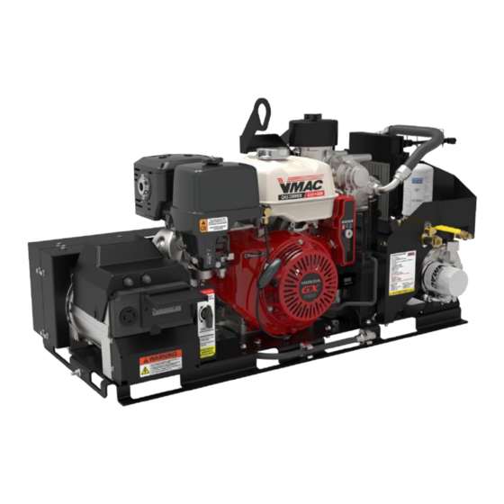
- Page 1 ® Gas Engine Driven 25 CFM Air Compressor with Generator Installation, Owner’s and Service Manual G300005 www.vmacair.com www.vmacair.com...
-
Page 3: Table Of Contents
Accessory Products from VMAC ........ - Page 4 Copyright © 2022 VMAC Global Technology Inc. All Rights Reserved. These materials are provided by VMAC for informational purposes only, without representation or warranty of any kind, and VMAC shall not be liable for errors or omissions with respect to the materials. The only warranties for VMAC...
-
Page 5: Safety
VMAC will not be held responsible for any liability, consequential damages, injuries, loss or damage to individuals or to equipment as a result of the failure of anyone to properly adhere to the procedures set out in this manual or standard safety practices. -
Page 6: Safety Precautions
Proper service and repair are important to the safety of the service technician and the safe, reliable operation of the equipment. Always use genuine VMAC and/or Honda replacement parts. - Page 7 240 Volts AC and can cause an electrical shock (regardless of whether equipment is plugged into the receptacles or not. VMAC - Vehicle Mounted Air Compressors VMAC Technical Support: 888-241-2289 VMAC Knowledge Base: kb.vmacair.com...
- Page 8 • Do not operate the system without guards in place. If the guards are damaged or missing, replace them before operating the equipment. VMAC - Vehicle Mounted Air Compressors VMAC Technical Support: 888-241-2289 VMAC Knowledge Base: kb.vmacair.com...
- Page 9 Never adjust or attempt to make any repairs to this system while the engine is running unless expressly instructed to do so. • Components and hoses under pressure could fail and cause serious injury or death. VMAC - Vehicle Mounted Air Compressors VMAC Technical Support: 888-241-2289 VMAC Knowledge Base: kb.vmacair.com...
-
Page 10: Warranty
1 October, 2015. Warranty Registration The VMAC warranty registration form is located near the back of this manual. This warranty registration form must be completed and sent to VMAC at the time of installation for any subsequent warranty claim to be considered valid. - Page 11 2. VMAC will provide direction for repair or replacement of the failed components. 3. If requested, failed parts must be returned to VMAC for evaluation. 4. Dealers may login to the VMAC website to view the "VMAC Labour Time Guide" (under “Agreements”) to see the allowable warranty labour times.
-
Page 12: General Information
Please contact VMAC for replacement hoses and further information. Ordering Parts To order parts, contact a VMAC dealer. The dealer will ask for the VMAC serial number, part number, description and quantity. Locate the nearest dealer online at www.vmacair.com/dealer-locator or call 1-877-912-6605. -
Page 13: Gas Engine Driven 25 Cfm Air Compressor Installation Manual
® Gas Engine Driven 25 CFM Air Compressor Installation Manual... -
Page 15: Installation Requirements
The belt guard is accessible and can be removed for service. • The engine oil drain, oil fill, fuel fill, and air filter are easily accessible for service (the VMAC Remote Oil Drain accessory can help facilitate servicing the engine and compressor oil P/N: A500043). •... -
Page 16: Ventilation Requirements
Exhaust and waste heat from the G30 system must be vented away from the system to prevent the gas engine from ingesting its exhaust and stalling. Figure 2 — Airflow diagram VMAC - Vehicle Mounted Air Compressors VMAC Technical Support: 888-241-2289 VMAC Knowledge Base: kb.vmacair.com... -
Page 17: Mounting Locations
Mounting Locations VMAC does not recommend mounting the unit at the back of the vehicle as the drag created when the vehicle is moving causes debris to be deposited (and accumulated) inside the unit. Enclosed Mounting with Pullout Drawer Enclosed mounting must incorporate one of the following to ensure... - Page 18 When selecting a top mount location, ensure the fuel shut off valve is easily accessible. The fuel valve must be shut off when the unit is not in use, including during transport. Figure 3 — Mounting locations VMAC - Vehicle Mounted Air Compressors VMAC Technical Support: 888-241-2289 VMAC Knowledge Base: kb.vmacair.com...
-
Page 19: Mounting The Compressor
(Figure 4). All dimensions are in inches. 42.8 22.0 29.9 39.75 19.13 21.4 Figure 4 — External dimensions VMAC - Vehicle Mounted Air Compressors VMAC Technical Support: 888-241-2289 VMAC Knowledge Base: kb.vmacair.com... - Page 20 Connect the downstream plumbing to the ball valve outlet. All dimensions are in inches. Ø 0.41 (×8) 18.0 12.0 12.0 14.75 0.56 Figure 5 — Base plate mounting configuration VMAC - Vehicle Mounted Air Compressors VMAC Technical Support: 888-241-2289 VMAC Knowledge Base: kb.vmacair.com...
- Page 21 While the American Welding Society® Safety & Health Fact Sheet No. 29 (Grounding of Portable and Vehicle Mounted Welding Generators) is a great reference for grounding the G30, VMAC recommends working/consulting with a certified electrician and local regulatory bodies when grounding the G30.
-
Page 23: Gas Engine Driven 25 Cfm Air Compressor Owner's Manual
® Gas Engine Driven 25 CFM Air Compressor Owner’s Manual... -
Page 25: Safety Features
The engine will not be able to be restarted until the system has cooled and the temperature switch has closed. VMAC - Vehicle Mounted Air Compressors VMAC Technical Support: 888-241-2289 VMAC Knowledge Base: kb.vmacair.com... - Page 26 20 A breakers (120 V / 240 V circuits) GFCI self test indicator light 120 Volt GFCI Figure 8 — Generator safety components VMAC - Vehicle Mounted Air Compressors VMAC Technical Support: 888-241-2289 VMAC Knowledge Base: kb.vmacair.com...
-
Page 27: Identifying Your System
(Figure 10). G300003 A BC 123 Model number Unique identifier Production date code Revision letter Figure 10 — System ID breakdown VMAC - Vehicle Mounted Air Compressors VMAC Technical Support: 888-241-2289 VMAC Knowledge Base: kb.vmacair.com... -
Page 28: Operating Principles
Operating Principles Air Compression The G30 uses a VMAC designed and manufactured flooded lobe, rotary screw compressor. The oil filled compressor housing contains 2 rotors. Compression occurs when air (at normal atmospheric pressure) enters a chamber where it is trapped between meshing rotor lobes. Cooled oil is injected into the rotors during compression to lubricate the rotors and bearings, absorb the heat of compression, and seal the rotor lobes to allow for efficient compression. - Page 29 Filtration VMAC rotary screw compressors are designed and machined to exacting tolerances. Foreign particles entering the compressor can damage system components such as seals, bearings, rotors, as well as the inside of the housing, resulting in performance losses and reduced system life.
-
Page 30: Extreme Climates And Elevation
Cold Environment Operation The G30 system is not designed or recommended for use in cold climates (below 0 °C / 32 °F) unless equipped with a VMAC cold climate kit (P/N: A500044). If equipped with the optional VMAC Cold Climate Kit... - Page 31 For engine oil recommendations in temperatures above 40 °C (104 °F) refer to the Honda GX390 Owner’s Manual supplied with the system (VMAC P/N: 1901066). Failure to follow the information supplied in the Honda Owner’s Manual may result in poor engine performance or engine damage.
-
Page 32: System Components And Specifications
WHASP Tank Compressor throttle control (OEM fuse located valve inside enclosure) Hour meter Battery Discharge valve Unloader valve Figure 11 — System overview (shroud removed for clarity) VMAC - Vehicle Mounted Air Compressors VMAC Technical Support: 888-241-2289 VMAC Knowledge Base: kb.vmacair.com... - Page 33 System Components (Back) (Figure 12) • Lifting eye • Belt shroud • Fuel fill • Exhaust shroud Lifting eye Fuel fill Exhaust shroud Belt shroud Figure 12 — System overview VMAC - Vehicle Mounted Air Compressors VMAC Technical Support: 888-241-2289 VMAC Knowledge Base: kb.vmacair.com...
-
Page 34: System Controls And Features
Key switch Recoil pull Choke (OEM fuse located start inside enclosure) Throttle Fuel shut off Unloader valve Hour meter control valve Figure 13 — System controls overview VMAC - Vehicle Mounted Air Compressors VMAC Technical Support: 888-241-2289 VMAC Knowledge Base: kb.vmacair.com... -
Page 35: Before Starting The G30
20° as this will affect lubrication and air/oil separation (Figure 14). Figure 14 — Do not exceed 20° grade New VMAC oil is clear and may be difficult to see in the sight glass. ☐ Clear any accumulated snow or ice from the G30 (page 28) ☐... -
Page 36: Starting The Engine
Ensure the throttle control valve is set to “COMPRESSOR ON”. If equipped with the optional VMAC Cold Climate kit, ensure the kit is turned off. Close the choke by moving the choke lever all the way to the left (Figure 15). - Page 37 10 seconds before operating the starter again. Using the starter for more than 5 seconds at a time will overheat the starter motor and may damage it. VMAC - Vehicle Mounted Air Compressors VMAC Technical Support: 888-241-2289 VMAC Knowledge Base: kb.vmacair.com...
- Page 38 (Figure 18). Choke lever Figure 18 — Choke ☐ See chapter “Compressor and Generator Operating Instructions” on page 40 for operating instructions. VMAC - Vehicle Mounted Air Compressors VMAC Technical Support: 888-241-2289 VMAC Knowledge Base: kb.vmacair.com...
- Page 39 Ensure the throttle control valve is set to “COMPRESSOR ON”. If equipped with the optional VMAC Cold Climate kit, ensure the kit is turned off. Turn the ignition key switch to the “ON” position.
- Page 40 7) Pull the starter grip lightly until resistance is felt, then pull briskly in the direction of the arrow. Return the starter grip gently to prevent damage to the starter (Figure 21). Figure 21 — Pull cord VMAC - Vehicle Mounted Air Compressors VMAC Technical Support: 888-241-2289 VMAC Knowledge Base: kb.vmacair.com...
- Page 41 (Figure 22). Choke lever Figure 22 — Choke ☐ See chapter “Compressor and Generator Operating Instructions” on page 40 for operating instructions. VMAC - Vehicle Mounted Air Compressors VMAC Technical Support: 888-241-2289 VMAC Knowledge Base: kb.vmacair.com...
-
Page 42: Compressor And Generator Operating Instructions
(Figure 24). Throttle control Set to “COMPRESSOR ON” Figure 24 — Throttle control valve VMAC - Vehicle Mounted Air Compressors VMAC Technical Support: 888-241-2289 VMAC Knowledge Base: kb.vmacair.com... - Page 43 The unloader valve must remain actuated while generator operation is selected. ☐ Turn the throttle control valve to “GENERATOR ON” (Figure 26). Throttle control Set to “GENERATOR ON” Figure 26 — Throttle control valve VMAC - Vehicle Mounted Air Compressors VMAC Technical Support: 888-241-2289 VMAC Knowledge Base: kb.vmacair.com...
-
Page 44: Stopping The Engine
VMAC - Vehicle Mounted Air Compressors VMAC Technical Support: 888-241-2289 VMAC Knowledge Base: kb.vmacair.com... -
Page 45: Recommended Accessories
44. Air receiver tanks are available for purchase through VMAC. See the “Accessory Products from VMAC” section of this manual on page 47 for more information. Pressure Gauge While not critical to system performance, a pressure gauge is important for fine tuning the system and simplifies any potential troubleshooting. -
Page 46: Air Receiver Tank
It also has the advantage of lowering the duty cycle of the compressor system. The VMAC compressor system automatically depressurizes when it is shut-down. The WHASP Tank has a built-in check valve which prevents the compressed air and any moisture in receiver tank from traveling back into the WHASP Tank. -
Page 47: Setup, Performance Testing And Adjustments
This system has been adjusted at the factory for general operation. System operation can be tested using the tools that will be operated by the system or by using the VMAC Test Tool (A700052) with the 30 CFM (1/8 in) orifice in the outlet to simulate tool use (Figure 29). -
Page 48: Engine Rpm Adjustment
The engine “low idle” and “high idle” screws are set at the factory and do not require adjustment. The throttle actuator will automatically raise and lower the engine speed dependent upon air demand. VMAC - Vehicle Mounted Air Compressors VMAC Technical Support: 888-241-2289 VMAC Knowledge Base: kb.vmacair.com... -
Page 49: Accessory Products From Vmac
(Tool oil not included). • Max air flow: up to 70 cfm / 150 psi. • Port size: 3/4 in NPT inlet and outlet. VMAC - Vehicle Mounted Air Compressors VMAC Technical Support: 888-241-2289 VMAC Knowledge Base: kb.vmacair.com... - Page 50 Compressor Service Kits 200 Hour or 6 Month Service Kit - Part number: A700219 Includes 4 L VMAC high performance compressor oil, oil filter, air filter, and next service due decal. 400 Hour or 1-Year Service Kit - Part number: A700220...
- Page 51 1/2 in × 50 ft Hose Reel Part number: A700007 Spring-loaded 1/2 in × 50 ft hose reel; steel construction; full flow shaft and swivel for maximum performance. VMAC - Vehicle Mounted Air Compressors VMAC Technical Support: 888-241-2289 VMAC Knowledge Base: kb.vmacair.com...
-
Page 52: General Maintenance Information
General Maintenance Information Routine Maintenance In order to maintain the VMAC warranty, VMAC’s maintenance schedule must be followed. Only genuine VMAC parts can be used to maintain the system. The compressor system does not contain reed valves or other easily fouled, fatigue prone components. - Page 53 All fasteners must be torqued to specifications. Use manufacturers’ torque values for OEM fasteners. The torque values supplied in Table 1 are intended for VMAC supplied components, or for use as a guide in the absence of a torque value provided by an OEM.
- Page 54 Installation Manuals and Illustrated Parts Lists (IPL) The installation manual and illustrated parts list are an invaluable resource for when inspecting, diagnosing or repairing the system. The installation manuals and IPL’s are available free of charge from VMAC. VMAC Installation Manuals https://www.vmacair.com/support/manuals/ VMAC IPLs https://www.vmacair.com/support/ipl/...
-
Page 55: Maintenance And Repair Safety
Use only genuine VMAC parts to maintain the system. Genuine VMAC parts are designed to work with the high pressure and heat generated by the compressor. Substituting genuine VMAC parts may void the warranty and could cause equipment damage, injury, or death. - Page 56 ☐ Remove the shroud, there are 3 fasteners that secure it to the base and WHASP Tank (Figure 31). Remove fasteners Figure 31 — Remove shroud VMAC - Vehicle Mounted Air Compressors VMAC Technical Support: 888-241-2289 VMAC Knowledge Base: kb.vmacair.com...
- Page 57 Figure 32 — Negative battery terminal ☐ Disconnect the spark plug wire (Figure 33). Disconnect spark plug wire Figure 33 — Spark plug wire VMAC - Vehicle Mounted Air Compressors VMAC Technical Support: 888-241-2289 VMAC Knowledge Base: kb.vmacair.com...
-
Page 58: Maintenance Schedule
The hours indicated below are those displayed on the hour meter. Service should be performed at whichever interval occurs first. Check the Illustrated Parts List for replacement part numbers or contact VMAC for more information. Compressor Maintenance Every 6 months or 200 hours (Service Kit P/N: A700219) •... - Page 59 Air filter. 3600037 Air filter. 9200039 Oil filter. 9200039 Oil filter. A700094 VMAC High performance oil (4 L). VMAC High A700094 3600088 Spin on coalescing filter. performance oil (4 L). 3600054 Valve, safety, 200 psi. 4500104 Muffler, Sintered Exhaust, 1/8.
-
Page 60: Regular Inspection Instructions
Wear appropriate Personal Protective Equipment and follow all industry standard safety practices. The VMAC supplied and approved compressor oil must be used in this system. Failure to use this special oil will result in damage to the compressor and will void warranty. - Page 61 Listen for the pressurized air to blowdown through the muffler on the WHASP Tank. Blowdown should be completed in approximately 20 seconds. ☐ If the muffler is showing signs of blockage, contact a local VMAC dealer for a replacement. A replacement blowdown muffler is included with the VMAC 400 hour service kit.
- Page 62 ☐ If the pressure relief valve is showing loss of functionality, contact a local VMAC dealer for a replacement. A replacement pressure relief valve is included with the VMAC 400 hour service kit.
- Page 63 Replace the cover and secure it with the filter cover retainer knob. Do not overtighten. Filter plate “step” Figure 37 — Compressor air filter and cover VMAC - Vehicle Mounted Air Compressors VMAC Technical Support: 888-241-2289 VMAC Knowledge Base: kb.vmacair.com...
- Page 64 Install the new drive belt (Figure 84 on page 105). ☐ Tension the new drive belt. ☐ Apply Loctite 242 (blue) to the (×10) fasteners and reinstall the belt guard. VMAC - Vehicle Mounted Air Compressors VMAC Technical Support: 888-241-2289 VMAC Knowledge Base: kb.vmacair.com...
- Page 65 The scavenge, pressure control and throttle control tubes are made of Polytetrafluoroethylene (PTFE) and are within specification to work with VMAC compressor oil and to withstand the high pressure and operating temperatures generated by the compressor. Standard air brake hose is not a suitable replacement.
-
Page 66: 200 Hour / 6 Month Service
Inspect the Viton O-ring on the oil drain plug for damage, hardness or defects and replace if necessary. ☐ Install and tighten the oil drain plug. ☐ Remove the oil filter (Figure 39). VMAC - Vehicle Mounted Air Compressors VMAC Technical Support: 888-241-2289 VMAC Knowledge Base: kb.vmacair.com... - Page 67 3/4 to 1 turn to seat the gasket. ☐ Remove the filler cap on the WHASP Tank. Fill the WHASP Tank with VMAC compressor oil until is reaches the “MAX” mark. The air compressor system holds approximately 4 L (1 USG) of oil (Figure 41).
- Page 68 Once the system has sat for 5 minutes, check the oil level through the sight glass. The level must be between the “MIN” and “MAX” level indicators. ☐ Verify there are no oil leaks. VMAC - Vehicle Mounted Air Compressors VMAC Technical Support: 888-241-2289 VMAC Knowledge Base: kb.vmacair.com...
-
Page 69: 400 Hour / 1 Year Service
Inspect the Viton O-ring on the oil drain plug for damage, hardness or defects and replace if necessary. ☐ Install and tighten the oil drain plug. ☐ Remove the oil filter (Figure 42). VMAC - Vehicle Mounted Air Compressors VMAC Technical Support: 888-241-2289 VMAC Knowledge Base: kb.vmacair.com... - Page 70 3/4 to 1 turn to seat the gasket. ☐ Remove the filler cap on the WHASP Tank. Fill the WHASP Tank with VMAC compressor oil until is reaches the “MAX” mark. The air compressor system holds approximately 4 L (1 USG) of oil (Figure 44).
- Page 71 Once the system has sat for 5 minutes, check the oil level through the sight glass. The level must be between the “MIN” and “MAX” level indicators. ☐ Verify there are no oil leaks. VMAC - Vehicle Mounted Air Compressors VMAC Technical Support: 888-241-2289 VMAC Knowledge Base: kb.vmacair.com...
-
Page 72: Engine Maintenance And Warranty Information
Engine Maintenance and Warranty Information The VMAC G30 uses the Honda GX390 engine. For engine service intervals and instructions, refer to the Honda Owner’s Manual (VMAC P/N: 1901066) supplied with the system. Failure to follow the instructions in the Honda Owner’s Manual could result in poor engine performance, engine damage and may void the Honda engine warranty. -
Page 73: Diagnostics And Trouble Shooting
For the following tests, isolate the G30 from all downstream (customer supplied) equipment. If the G30 is still within the warranty period, contact VMAC prior to commencing any diagnostics or repairs. Problem diagnosis should follow sound, recognized practices. Quick and accurate diagnosis of problems should involve the following: •... - Page 74 15. Symptom Possible Cause Corrective Action Torque fasteners, use Loose fasteners. appropriate thread locking compound. Excessive vibration. Replace components as Belt or pulley worn. needed. VMAC - Vehicle Mounted Air Compressors VMAC Technical Support: 888-241-2289 VMAC Knowledge Base: kb.vmacair.com...
- Page 75 Spark arrester clogged. arrester. See enclosure mounting Mounted in enclosure. parameters on page 15. Ensure unloader valve Compressor engaged while is triggered while using generator in use. generator. VMAC - Vehicle Mounted Air Compressors VMAC Technical Support: 888-241-2289 VMAC Knowledge Base: kb.vmacair.com...
- Page 76 Oil comes out of the blowdown muffler. Faulty blowdown shuttle Replace blowdown shuttle valve. valve. Replace blowdown valve Blowdown valve failure. assembly. VMAC - Vehicle Mounted Air Compressors VMAC Technical Support: 888-241-2289 VMAC Knowledge Base: kb.vmacair.com...
- Page 77 Symptom Possible Cause Corrective Action Air leaking from small hole This is normal and as per None required. in inlet valve regulator cap. design. VMAC - Vehicle Mounted Air Compressors VMAC Technical Support: 888-241-2289 VMAC Knowledge Base: kb.vmacair.com...
- Page 78 Replace throttle actuator. Symptom Possible Cause Corrective Action Voltage fluctuation from Unloader valve not engaged Discontinue air usage and generator. and compressor in use. engage unloader valve. VMAC - Vehicle Mounted Air Compressors VMAC Technical Support: 888-241-2289 VMAC Knowledge Base: kb.vmacair.com...
- Page 79 Diagnostic Tools VMAC Air Test Tool (P/N: A700052) To properly diagnose VMAC’s G30, a VMAC Air Test Tool (P/N: A700052), or equivalent, is required (Figure 46). For testing and diagnosis, install the 30 CFM (1/8 in) orifice. JIC Adapters Orifice...
-
Page 80: System Adjustments
Remove the push-to-connect fitting from the unloader valve and plug the valve using a 1/4 in NPT plug (Figure 48). 1/4 in NPT plug Figure 48 — Plug unloader valve VMAC - Vehicle Mounted Air Compressors VMAC Technical Support: 888-241-2289 VMAC Knowledge Base: kb.vmacair.com... - Page 81 ☐ Connect the VMAC Air Test Tool (P/N: A700052) to the discharge fitting of the WHASP Tank. ☐ With the ball valve on the test tool closed, run the system and note the maximum pressure achieved (factory default is 140 psi).
- Page 82 Make a locating mark on both the “Pressure Adjustment Locknut” and the “Pressure Adjustment Screw” (Figure 50). Locating marks Pressure Adjustment Screw Pressure Adjustment Locknut Figure 50 — Adjusting the Unloader Valve VMAC - Vehicle Mounted Air Compressors VMAC Technical Support: 888-241-2289 VMAC Knowledge Base: kb.vmacair.com...
- Page 83 While securely holding the “Pressure Adjustment Screw”, tighten the “Pressure Adjustment Locknut”. ☐ Test the system and repeat the steps above (if necessary) until the system unloads at 135 psi. VMAC - Vehicle Mounted Air Compressors VMAC Technical Support: 888-241-2289 VMAC Knowledge Base: kb.vmacair.com...
-
Page 84: Compressor Regulation And Throttle Actuator Testing
Compressor Regulation and Throttle Actuator Testing Throttle Control (C) VMAC configures the Honda engine throttle to be wide open in its neutral state (0 psi). Engine rpm is controlled via the throttle actuator which is operated by air pressure from the unloader valve. - Page 85 Figure 54 — Throttle actuator (“COMPRESSOR ON”) Throttle Control (GENERATOR ON) When the VMAC throttle control is set to “GENERATOR ON”, the air pressure from the discharge valve is blocked and the throttle is vented to atmosphere via a sintered muffler, allowing the Honda throttle to remain wide open (neutral state) (Figure 55).
- Page 86 (Figure 57). 1/4 in compressor scavenge fitting 1/4 in WHASP Tank scavenge fitting (with one-way check valve) 1/4 in PTFE scavenge tube Figure 57 — Scavenge tube VMAC - Vehicle Mounted Air Compressors VMAC Technical Support: 888-241-2289 VMAC Knowledge Base: kb.vmacair.com...
- Page 87 3/16 in compressor fitting at inlet regulator 1/4 in PTFE pressure control tube Discharge valve Figure 59 — 3/16 in Pressure control tube (Belt guard removed for clarity) VMAC - Vehicle Mounted Air Compressors VMAC Technical Support: 888-241-2289 VMAC Knowledge Base: kb.vmacair.com...
- Page 88 Install the PTFE test tool (Figure 47 and Table 4 on page 77) on the 1/4 in throttle tube on the engine side of the 1/4 in PTFE Union (Figure 60). VMAC - Vehicle Mounted Air Compressors VMAC Technical Support: 888-241-2289...
- Page 89 Figure 61 — Test equipment installed VMAC - Vehicle Mounted Air Compressors VMAC Technical Support: 888-241-2289 VMAC Knowledge Base: kb.vmacair.com...
- Page 90 “COMPRESSOR ON” Start the engine, and monitor both pressure gauges: As the pressure indicated on the VMAC test tool gauge reaches 135 psi, the gauge connected to the 1/4 in PTFE tube should indicate 135 psi. If the pressure on the gauge connected to the 1/4 in PTFE tube does not increase, confirm the manual unloader valve has not been adjusted.
- Page 91 Air pressure generated by the compressor is controlled mechanically via the inlet valve poppet. When the inlet valve poppet is open, the compressor will build air pressure (Figure 63). Poppet O-ring Figure 63 — Inlet valve poppet open VMAC - Vehicle Mounted Air Compressors VMAC Technical Support: 888-241-2289 VMAC Knowledge Base: kb.vmacair.com...
- Page 92 When the inlet valve poppet is closed, the compressor will not build air pressure (Figure 64). Poppet O-ring Figure 64 — Inlet valve poppet closed VMAC - Vehicle Mounted Air Compressors VMAC Technical Support: 888-241-2289 VMAC Knowledge Base: kb.vmacair.com...
-
Page 93: Electrical Components And Testing
Electrical Components and Testing For generator specific testing information, search the VMAC Knowledge Base, or contact VMAC technical support. Figure 65 — VMAC electrical harness schematic VMAC - Vehicle Mounted Air Compressors VMAC Technical Support: 888-241-2289 VMAC Knowledge Base: kb.vmacair.com... - Page 94 Use a “jumper” to supply 12 V to pin “A” of the fan plug and a ground to pin “B” of the plug to confirm the fan runs when power is supplied. Figure 66 — WHASP Tank cooling fan VMAC - Vehicle Mounted Air Compressors VMAC Technical Support: 888-241-2289 VMAC Knowledge Base: kb.vmacair.com...
- Page 95 Testing ☐ Use a multimeter to measure the resistance through the switch. The resistance should be 0 Ω when the system is cold. VMAC - Vehicle Mounted Air Compressors VMAC Technical Support: 888-241-2289 VMAC Knowledge Base: kb.vmacair.com...
-
Page 96: Component Repair / Replacement
Remove the shroud and disconnect the negative battery cable. Undo the battery hold down strap (Figure 69). Negative battery cable Restraining strap Figure 69 — Battery hold down VMAC - Vehicle Mounted Air Compressors VMAC Technical Support: 888-241-2289 VMAC Knowledge Base: kb.vmacair.com... - Page 97 Pull the battery out of the front of the unit, once it is clear, disconnect the positive battery terminal (Figure 70). Figure 70 — Battery removal ☐ Install the battery in the reverse order. VMAC - Vehicle Mounted Air Compressors VMAC Technical Support: 888-241-2289 VMAC Knowledge Base: kb.vmacair.com...
- Page 98 ☐ Remove the bolt from the side of the compressor (Figure 71). Remove compressor mounting bolt Figure 71 — Remove compressor VMAC - Vehicle Mounted Air Compressors VMAC Technical Support: 888-241-2289 VMAC Knowledge Base: kb.vmacair.com...
- Page 99 Lift the compressor up and away from the belt guard to remove it (Figure 73). Figure 73 — Remove compressor Do not remove the compressor pulley when reinstalling the compressor. ☐ Install the compressor in the reverse order. VMAC - Vehicle Mounted Air Compressors VMAC Technical Support: 888-241-2289 VMAC Knowledge Base: kb.vmacair.com...
- Page 100 Ensure the O-ring is not defective or damaged. ☐ Install the inlet valve in the reverse order. Loctite is not required on the inlet valve bolts. VMAC - Vehicle Mounted Air Compressors VMAC Technical Support: 888-241-2289 VMAC Knowledge Base: kb.vmacair.com...
- Page 101 Apply Loctite 425 (low strength adhesive) and install the new fan with the (×4) bolts. ☐ Reconnect the fan electrical connector. ☐ Test the system. Remove fasteners (×4) Figure 75 — Remove WHASP Fan VMAC - Vehicle Mounted Air Compressors VMAC Technical Support: 888-241-2289 VMAC Knowledge Base: kb.vmacair.com...
- Page 102 Apply Loctite 567 (thread sealant) to the new fan temperature switch and install it into the WHASP Tank cooler. ☐ Connect the fan temperature switch to the harness. Temperature switch Figure 76 — Fan temperature switch removal VMAC - Vehicle Mounted Air Compressors VMAC Technical Support: 888-241-2289 VMAC Knowledge Base: kb.vmacair.com...
- Page 103 WHASP Tank cooler. ☐ Connect the compressor temperature switch to the harness. ☐ Reinstall the WHASP Tank shroud. Temperature switch Figure 77 — Compressor temperature switch removal VMAC - Vehicle Mounted Air Compressors VMAC Technical Support: 888-241-2289 VMAC Knowledge Base: kb.vmacair.com...
- Page 104 ☐ Remove the WHASP Tank. Remove bolts (×4) Remove nuts (×4) Figure 78 — Remove WHASP Tank ☐ Install the WHASP Tank in the reverse order. VMAC - Vehicle Mounted Air Compressors VMAC Technical Support: 888-241-2289 VMAC Knowledge Base: kb.vmacair.com...
- Page 105 Figure 79 — Remove throttle switch mount bracket fastener ☐ Remove the belt guard and generator rear cover (Figure 80). Remove (×14) belt guard fasteners Figure 80 — Remove belt guards VMAC - Vehicle Mounted Air Compressors VMAC Technical Support: 888-241-2289 VMAC Knowledge Base: kb.vmacair.com...
- Page 106 Taking note of the location for the star grounding washer, remove the rear generator fasteners (Figure 82). Grounding washer Figure 82 — Remove rear generator fasteners VMAC - Vehicle Mounted Air Compressors VMAC Technical Support: 888-241-2289 VMAC Knowledge Base: kb.vmacair.com...
- Page 107 Ensure the front generator fasteners are partially threaded into the generator prior to reinstallation. ☐ Install the generator in the reverse order. ☐ Compressor and generator belt routing (Figure 84). Figure 84 — Belt routing VMAC - Vehicle Mounted Air Compressors VMAC Technical Support: 888-241-2289 VMAC Knowledge Base: kb.vmacair.com...
-
Page 109: G300005 Illustrated Parts List (Ipl)
® G300005 Illustrated Parts List (IPL) www.vmacair.com... -
Page 111: Illustrated Parts List
SPACER 1560517 NUT, NYLOCK SS, M3 1500710 SCREW, SHCS, M3 X 14 1500711 CLIP, 1/4 ID, ROUTING 1200998 BRACE, BOTTOM 1772019 HOSE, CRIMPED, 3/4” X 19” VMAC - Vehicle Mounted Air Compressors VMAC Technical Support: 888-241-2289 VMAC Knowledge Base: kb.vmacair.com... - Page 112 LABEL, FUEL SHUT OFF 9500662 ASSY, AC - GENERATOR 3200627 SPACER, IDLER 1300043 IDLER, PULLEY, 4 RIB, STEEL 1520540 BOLT, HHCS, FLHD, M10 X 1.50 X 55 VMAC - Vehicle Mounted Air Compressors VMAC Technical Support: 888-241-2289 VMAC Knowledge Base: kb.vmacair.com...
- Page 113 LOOM, SPLIT PLASTIC, 1/4, HIGH TEMP *Items 54 – 55, 86 – 99 not shown in Figure 85 on page 112 or Figure 86 on page 113. VMAC - Vehicle Mounted Air Compressors VMAC Technical Support: 888-241-2289 VMAC Knowledge Base: kb.vmacair.com...
- Page 114 Figure 85 — Kit pack list VMAC - Vehicle Mounted Air Compressors VMAC Technical Support: 888-241-2289 VMAC Knowledge Base: kb.vmacair.com...
- Page 115 Figure 86 — Kit pack list VMAC - Vehicle Mounted Air Compressors VMAC Technical Support: 888-241-2289 VMAC Knowledge Base: kb.vmacair.com...
- Page 116 1.10 3501179 CIR BRKR, THRM 20A PUSH-RESET 1.11 3501620 RCPT, 20A 250V, NEMA L14-20R 1.12 3501619 RCPT, 20A 125V, GFCI, NEMA 5-20R Figure 87 — Generator VMAC - Vehicle Mounted Air Compressors VMAC Technical Support: 888-241-2289 VMAC Knowledge Base: kb.vmacair.com...
- Page 117 PIPE FTG, PLUG SKT HEAD, 1/8 5000162 CONNECT,BRASS NPT-POLY,3/16-1/8 NPT 4800812 ASSEMBLY,4 RIB PULLEY, G30 1520626 BOLT,HHCS,PL,G10.9,FL, M6-1.0 X 30 3550974 ASSEMBLY, SWITCH, THERMAL, 140C Figure 88 — Compressor Assembly (P190004) VMAC - Vehicle Mounted Air Compressors VMAC Technical Support: 888-241-2289 VMAC Knowledge Base: kb.vmacair.com...
- Page 118 PLATE, INNER FILTER 3600037 ELEMENT, FILTER, PAPER 3600066 COVER, AIR FILTER, PLASTIC 5830070 O-RING, VITON, 2 9/16 ID X 3/32 Figure 89 — Inlet Valve Sub Components VMAC - Vehicle Mounted Air Compressors VMAC Technical Support: 888-241-2289 VMAC Knowledge Base: kb.vmacair.com...
- Page 119 4900236 FTG, 90, #4MORB-1/4”MNPT, VITON 3600166 FITTING, NIPPLE, FILTER 6000719 SHROUD, FAN, WHASP TANK 1500691 SCREW, SELF TAPPING, #10-16 X 1/2 3550958 FAN, PULLER, 7.5”, GT280 VMAC - Vehicle Mounted Air Compressors VMAC Technical Support: 888-241-2289 VMAC Knowledge Base: kb.vmacair.com...
- Page 120 BOLT, HHCS, M6 X 1.0 X 14 FL PL 1520570 BOLT,HHCS FL LK PL, M8 X 1.25 X 16 1570519 WASHER, EXT SERRATED LOCK, M8 *Item 32 includes O-ring. Figure 90 — WHASP Tank VMAC - Vehicle Mounted Air Compressors VMAC Technical Support: 888-241-2289 VMAC Knowledge Base: kb.vmacair.com...
- Page 121 Notes VMAC - Vehicle Mounted Air Compressors VMAC Technical Support: 888-241-2289 VMAC Knowledge Base: kb.vmacair.com...
-
Page 122: Warranty Registration
Warranty Registration This form must be fully completed and returned to VMAC at the time the vehicle is put into service. Warranty may be void if this form is not received by VMAC within 3 months of receiving the vehicle, or 200 hours of operation, whichever occurs first. - Page 124 Manufactured by ® 888-241-2289 tech@vmacair.com 877-740-3202 warranty@vmacair.com www.vmacair.com kb.vmacair.com 1333 Kipp Road, Nanaimo, B.C., V9X 1R3 Canada...
Need help?
Do you have a question about the G300005 and is the answer not in the manual?
Questions and answers