
Subscribe to Our Youtube Channel
Related Manuals for Vmac G300004


Summary of Contents for Vmac G300004
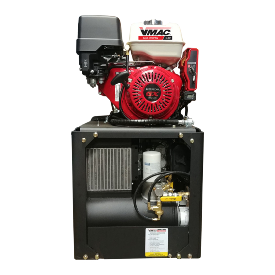
- Page 1 ® Gas Engine Driven 30 CFM Air Compressor G300004 Installation, Owner and Service Manual www.vmacair.com www.vmacair.com...
-
Page 3: Table Of Contents
G300004 Owner’s Manual ........ - Page 4 Copyright © 2020 VMAC Global Technology Inc. All Rights Reserved. These materials are provided by VMAC for informational purposes only, without representation or warranty of any kind, and VMAC shall not be liable for errors or omissions with respect to the materials. The only warranties for VMAC...
-
Page 5: Safety
VMAC will not be held responsible for any liability, consequential damages, injuries, loss or damage to individuals or to equipment as a result of the failure of anyone to properly adhere to the procedures set out in this manual or standard safety practices. -
Page 6: Safety Precautions
Proper service and repair are important to the safety of the service technician and the safe, reliable operation of the equipment. Always use genuine VMAC and/or Honda replacement parts. - Page 7 • Follow all safety precautions when jump starting or charging a battery. • Never attempt to jump start a frozen battery. • Never overcharge a battery. VMAC - Vehicle Mounted Air Compressors VMAC Technical Support: 888-241-2289 VMAC Knowledge Base: kb.vmacair.com...
- Page 8 • Do not operate the system without guards in place. If the guards are damaged or missing, replace them before operating the equipment. VMAC - Vehicle Mounted Air Compressors VMAC Technical Support: 888-241-2289 VMAC Knowledge Base: kb.vmacair.com...
- Page 9 Never adjust or attempt to make any repairs to this system while the engine is running unless expressly instructed to do so. • Components and hoses under pressure could fail and cause serious injury or death. VMAC - Vehicle Mounted Air Compressors VMAC Technical Support: 888-241-2289 VMAC Knowledge Base: kb.vmacair.com...
-
Page 10: Warranty
1 October, 2015. Warranty Registration The VMAC warranty registration form is located near the back of this manual. This warranty registration form must be completed and sent to VMAC at the time of installation for any subsequent warranty claim to be considered valid. - Page 11 2. VMAC will provide direction for repair or replacement of the failed components. 3. If requested, failed parts must be returned to VMAC for evaluation. 4. Dealers may login to the VMAC website to view the "VMAC Labour Time Guide" (under “Agreements”) to see the allowable warranty labour times.
-
Page 12: General Information
Please contact VMAC for replacement hoses and further information. Ordering Parts To order parts, contact a VMAC dealer. The dealer will ask for the VMAC serial number, part number, description and quantity. Locate the nearest dealer online at www.vmacair.com/dealer-locator or call 1-877-912-6605. -
Page 13: G300004 Installation Manual
® G300004 Installation Manual VMAC - Vehicle Mounted Air Compressors VMAC Technical Support: 888-241-2289 VMAC Knowledge Base: kb.vmacair.com... -
Page 15: Installation Requirements
See page 23 of this manual for an overview of the various components. When determining a mounting location for the G300004, ensure the following conditions are met (see Figure 1 on page 15): • The fuel shut off valve is easily accessible (the fuel valve must be shut off when the unit is not in use, including during transport). -
Page 16: Ventilation Requirements
12 in of clearance in front of it, however unobstructed venting to open atmosphere is preferred. The engine exhaust must be vented away from the G300004 and toward a safe location (the exhaust tip can be rotated to change the exhaust direction if needed). - Page 17 Figure 1 — Airflow diagram (some frame components removed for clarity) VMAC - Vehicle Mounted Air Compressors VMAC Technical Support: 888-241-2289 VMAC Knowledge Base: kb.vmacair.com...
-
Page 18: Mounting Locations
Top mounted is the preferred mounting location. Placing the unit on top of the service body provides the best access to cool fresh air. Maintain a minimum of 6 in between the sides of the G300004 and 1 ft in front of the WHASP cooling fan and all other solid objects (Figure 2). - Page 19 Figure 2 — Mounting locations VMAC - Vehicle Mounted Air Compressors VMAC Technical Support: 888-241-2289 VMAC Knowledge Base: kb.vmacair.com...
-
Page 20: Mounting The Compressor
Mounting the Compressor External dimensions with the base plate ☐ Locate a suitable mounting position for the G300004. Place the unit in its intended location and check for clearances to any other objects (Figure 3). All dimensions are in inches. - Page 21 There are 4 holes in the base plate for mounting the G300004 (Figure 4). Drill 4 holes in the surface that the G300004 will be mounted to. Use a minimum of (×4) 3/8 in or M10 fasteners. Ensure washers are used in addition to locknuts or Loctite 242 (blue) on the mounting fasteners.
-
Page 23: G300004 Owner's Manual
® G300004 Owner’s Manual VMAC - Vehicle Mounted Air Compressors VMAC Technical Support: 888-241-2289 VMAC Knowledge Base: kb.vmacair.com... -
Page 25: System Overview
(OEM fuse located throttle inside enclosure) Hour meter / tachometer Choke Fuel shut Unloader valve Engine oil Recoil Engine oil dipstick starter drain Figure 5 — System overview VMAC - Vehicle Mounted Air Compressors VMAC Technical Support: 888-241-2289 VMAC Knowledge Base: kb.vmacair.com... - Page 26 Figure 6 — System overview (some components removed for clarity) The electric fan on the WHASP Tank can turn on at any time. This is normal operation. VMAC - Vehicle Mounted Air Compressors VMAC Technical Support: 888-241-2289 VMAC Knowledge Base: kb.vmacair.com...
-
Page 27: Safety Features
Read pages 2 – 10 of this manual prior to installation or operation of the G300004. G300004 Safety Components (Figure 7) • 200 psi pressure relief valve in the separation manifold. •... -
Page 28: Identifying Your System
(Figure 9). A BC 123 G300004 Model number Unique identifier Production date code Revision letter Figure 9 — System ID breakdown VMAC - Vehicle Mounted Air Compressors VMAC Technical Support: 888-241-2289 VMAC Knowledge Base: kb.vmacair.com... -
Page 29: Operating Principles
Operating Principles Air Compression The G300004 uses a VMAC designed and manufactured flooded lobe, rotary screw compressor. The oil filled compressor housing contains 2 rotors. Compression occurs when air (at normal atmospheric pressure) enters a chamber where it is trapped between meshing rotor lobes. Cooled oil is injected into the rotors during compression to lubricate the rotors and bearings, absorb the heat of compression, and seal the rotor lobes to allow for efficient compression. - Page 30 Filtration VMAC rotary screw compressors are designed and machined to exacting tolerances. Foreign particles entering the compressor can damage system components such as seals, bearings, rotors, as well as the inside of the housing, resulting in performance losses and reduced system life.
-
Page 31: Extreme Climates And Elevation
Cold Environment Operation The G300004 system is not designed or recommended for use in cold climates (below 0 °C / 32 °F) unless equipped with a VMAC cold climate kit (P/N: A500044). If equipped with the optional VMAC Cold Climate Kit... - Page 32 A receiver tank can help prevent overheating issues by lowering the duty cycle of the compressor. The G300004 has been designed to operate from 0 to 3,500 feet above sea level. Operation above 3,500 feet may limit the compressor performance and may cause the engine to stall.
-
Page 33: Operating The G300004
20° as this will affect lubrication and air/oil separation (Figure 10). Figure 10 — Do not exceed 20° grade New VMAC oil is clear and may be difficult to see in the sight glass. ☐ Check the compressor oil level and condition (Note: If crank case is filled with fuel, check to see if fuel shutoff was left open after last shutdown as this is the most common cause) (page 51). -
Page 34: Starting And Stopping The Engine
1) If equipped with the optional VMAC Cold Climate kit, ensure the kit is turned off. 2) Close the choke by moving the choke lever all the way to the left (Figure 11). - Page 35 10 seconds before operating the starter again. Using the starter for more than 5 seconds at a time will overheat the starter motor and may damage it. VMAC - Vehicle Mounted Air Compressors VMAC Technical Support: 888-241-2289 VMAC Knowledge Base: kb.vmacair.com...
- Page 36 While the unloader valve is actuated the system will only build to 40 psi. Once the engine has warmed up, close the unloader valve to allow the system to build to full system pressure. VMAC - Vehicle Mounted Air Compressors VMAC Technical Support: 888-241-2289 VMAC Knowledge Base: kb.vmacair.com...
- Page 37 1) If equipped with the optional VMAC Cold Climate kit, ensure the kit is turned off. 2) Close the choke by moving the choke lever all the way to the left (Figure 16).
- Page 38 While the unloader valve is actuated the system will only build to 40 psi. Once the engine has warmed up, close the unloader valve to allow the system to build to full system pressure. VMAC - Vehicle Mounted Air Compressors VMAC Technical Support: 888-241-2289 VMAC Knowledge Base: kb.vmacair.com...
- Page 39 VMAC - Vehicle Mounted Air Compressors VMAC Technical Support: 888-241-2289 VMAC Knowledge Base: kb.vmacair.com...
-
Page 40: Recommended Accessories
Receiver Tank A receiver tank reduces the duty cycle of the compressor, and can help the G300004 run tools with higher cfm requirements. It can also provide a buffer so that tools can be used immediately upon system start up. -
Page 41: Air Receiver Tank
It also has the advantage of lowering the duty cycle of the compressor system. The VMAC compressor system automatically depressurizes when it is shut-down. The WHASP Tank has a built-in check valve which prevents the compressed air and any moisture in receiver tank from traveling back into the WHASP Tank. -
Page 42: Setup, Performance Testing And Adjustments
This system has been adjusted at the factory for general operation. System operation can be tested using the tools that will be operated by the system or by using the VMAC Test Tool (A700052) with the 30 cfm (1/8 in) orifice in the outlet to simulate tool use (Figure 23). -
Page 43: Engine Rpm Adjustment
The engine “low idle” and “high idle” screws are set at the factory and do not require adjustment. The throttle actuator will automatically raise and lower the engine speed dependent upon air demand. VMAC - Vehicle Mounted Air Compressors VMAC Technical Support: 888-241-2289 VMAC Knowledge Base: kb.vmacair.com... -
Page 44: Accessory Products From Vmac
Cold Climate Kit Part number: A500044; A520004 (factory installed) Cold climate heater package for operating the G300004 in cold climates; proven at temperatures of -30 °C (-22 °F); (×2) 120 V AC Heaters; requires 600 W total power. 600 W Power Inverter Part number: A500181 600 W, 12 V power inverter;... - Page 45 Air receiver tanks are used for lowering compressor duty cycle and removing water from compressed air; recommended for optimum operation of all VMAC Gas Driven, Diesel Driven, Hydraulic, and UNDERHOOD30 air compressors. Manufactured to FMVSS 121 standard; includes fittings, 160 psi pressure relief valve, and tank drain.
- Page 46 1/2 in × 50 ft Hose Reel Part number: A700007 Spring-loaded 1/2 in × 50 ft hose reel; steel construction; full flow shaft and swivel for maximum performance. VMAC - Vehicle Mounted Air Compressors VMAC Technical Support: 888-241-2289 VMAC Knowledge Base: kb.vmacair.com...
-
Page 47: General Maintenance Information
Any contamination will cause rapid and severe damage to components. The G300004 must be run a minimum of once every 30 days for at least 30 minutes to prevent impact damage and premature bearing failure in the compressor due to vibration from the vehicle. Regularly running the system will also help to vaporise and exhaust any water that has condensed and accumulated in the WHASP Tank. - Page 48 All fasteners must be torqued to specifications. Use manufacturers’ torque values for OEM fasteners. The torque values supplied in Table 1 are intended for VMAC supplied components, or for use as a guide in the absence of a torque value provided by an OEM.
-
Page 49: Maintenance And Repair Safety
Use only genuine VMAC parts to maintain the system. Genuine VMAC parts are designed to work with the high pressure and heat generated by the compressor. Substituting genuine VMAC parts may void the warranty and could cause equipment damage, injury, or death. - Page 50 ☐ Disconnect the negative battery terminal (Figure 25). Disconnect negative battery terminal Figure 25 — Negative battery terminal (shroud removed for clarity) VMAC - Vehicle Mounted Air Compressors VMAC Technical Support: 888-241-2289 VMAC Knowledge Base: kb.vmacair.com...
- Page 51 ☐ Disconnect the spark plug wire (Figure 26). Disconnect spark plug wire Figure 26 — Spark plug wire VMAC - Vehicle Mounted Air Compressors VMAC Technical Support: 888-241-2289 VMAC Knowledge Base: kb.vmacair.com...
-
Page 52: Maintenance Schedule
Maintenance Schedule In order to maintain the warranty on the G300004, use only genuine VMAC and/or Honda replacement parts to service the system. Refer to the Honda Owner’s Manual for the engine maintenance schedule and instructions. To ensure proper performance and long service life, the following maintenance schedule must be adhered to. -
Page 53: Regular Inspection Instructions
Wear appropriate Personal Protective Equipment and follow all industry standard safety practices. The VMAC supplied and approved compressor oil must be used in this system. Failure to use this special oil will result in damage to the compressor and will void warranty. - Page 54 Listen for the pressurized air to blowdown through the muffler on the WHASP Tank. Blowdown should be completed in approximately 20 seconds. ☐ If the muffler is showing signs of blockage, contact a local VMAC dealer for a replacement. A replacement blowdown muffler is included with the VMAC 400 hour service kit.
- Page 55 ☐ If the pressure relief valve is showing loss of functionality, contact a local VMAC dealer for a replacement. A replacement pressure relief valve is included with the VMAC 400 hour service kit.
- Page 56 Replace the cover and secure it with the filter cover retainer knob. Do not overtighten. Filter plate “step” Figure 30 — Compressor air filter and cover (PTFE lines removed for clarity) VMAC - Vehicle Mounted Air Compressors VMAC Technical Support: 888-241-2289 VMAC Knowledge Base: kb.vmacair.com...
- Page 57 Figure 31 — Inspecting the drive belt Description Part # Belt (Gates part number K040438) 1620365 Tensioner (Ford part number 7C3Z-6B209-D) 3300036 Table 4 — Belt part numbers and tension VMAC - Vehicle Mounted Air Compressors VMAC Technical Support: 888-241-2289 VMAC Knowledge Base: kb.vmacair.com...
- Page 58 The scavenge, pressure control and throttle control tubes are made of Polytetrafluoroethylene (PTFE) and are within specification to work with VMAC compressor oil and to withstand the high pressure and operating temperatures generated by the compressor. Standard air brake hose is not a suitable replacement.
-
Page 59: 200 Hour / 6 Month Service
4 L (1 USG) (Figure 33). Oil drain plug Oil filter Figure 33 — Compressor oil filter (some components removed for clarity) VMAC - Vehicle Mounted Air Compressors VMAC Technical Support: 888-241-2289 VMAC Knowledge Base: kb.vmacair.com... - Page 60 Spin the filter onto the threaded nipple until the gasket contacts the sealing surface on the tank, then tighten the filter an additional 3/4 to 1 turn to seat the gasket. VMAC - Vehicle Mounted Air Compressors VMAC Technical Support: 888-241-2289 VMAC Knowledge Base: kb.vmacair.com...
-
Page 61: 400 Hour / 1 Year Service
4 L (1 USG) (Figure 35). Oil drain plug Oil filter Figure 35 — Compressor oil filter (some components removed for clarity) VMAC - Vehicle Mounted Air Compressors VMAC Technical Support: 888-241-2289 VMAC Knowledge Base: kb.vmacair.com... - Page 62 Spin the filter onto the threaded nipple until the gasket contacts the sealing surface on the tank, then tighten the filter an additional 3/4 to 1 turn to seat the gasket. VMAC - Vehicle Mounted Air Compressors VMAC Technical Support: 888-241-2289 VMAC Knowledge Base: kb.vmacair.com...
- Page 63 ☐ Remove the filler cap on the WHASP Tank. Fill the WHASP Tank with VMAC compressor oil until is reaches the “MAX” mark. The air compressor system holds approximately 4 L (1 USG) of oil (Figure 37). Figure 37 — Compressor oil fill ☐...
- Page 64 Once the system has sat for 5 minutes, check the oil level through the sight glass. The level must be between the “MIN” and “MAX” level indicators. ☐ Verify there are no oil leaks. VMAC - Vehicle Mounted Air Compressors VMAC Technical Support: 888-241-2289 VMAC Knowledge Base: kb.vmacair.com...
-
Page 65: Engine Maintenance And Warranty Information
Engine Maintenance and Warranty Information The VMAC G300004 uses the Honda GX390 engine (type: QNR2). For engine service intervals and instructions, refer to the Honda Owner’s Manual supplied with the system (VMAC P/N: 1901066). Failure to follow the instructions in the Honda Owner’s Manual could result in poor engine performance, engine damage and may void the Honda engine warranty. -
Page 66: Diagnostics And Trouble Shooting
For the following tests, isolate the G300004 from all downstream (customer supplied) equipment. If the G300004 is still within the warranty period, contact VMAC prior to commencing any diagnostics or repairs. Problem diagnosis should follow sound, recognized practices. Quick and accurate diagnosis of problems should involve the following: •... - Page 67 Add oil to engine. Spark plug gap. Replace spark plug. Clean or replace the spark Spark arrester clogged. arrester. See enclosure mounting Mounted in enclosure. parameters on page 16. VMAC - Vehicle Mounted Air Compressors VMAC Technical Support: 888-241-2289 VMAC Knowledge Base: kb.vmacair.com...
- Page 68 Fuel shut off lever left on Remove spark plug. Use recoil during transport, fuel flooded starter to drain cylinder. crank case and cylinder. Change oil and filter. VMAC - Vehicle Mounted Air Compressors VMAC Technical Support: 888-241-2289 VMAC Knowledge Base: kb.vmacair.com...
- Page 69 Oil comes out of the blowdown muffler. Faulty blowdown shuttle Replace blowdown shuttle valve. valve. Replace blowdown valve Blowdown valve failure. assembly. VMAC - Vehicle Mounted Air Compressors VMAC Technical Support: 888-241-2289 VMAC Knowledge Base: kb.vmacair.com...
- Page 70 Corrective Action Air leaking from small hole in This is normal and as per None required. inlet valve regulator cap. design. Table 5 — Trouble shooting table VMAC - Vehicle Mounted Air Compressors VMAC Technical Support: 888-241-2289 VMAC Knowledge Base: kb.vmacair.com...
- Page 71 Diagnostic Tools VMAC Air Test Tool (P/N: A700052) To properly diagnose VMAC’s G300004, a VMAC Air Test Tool (P/N: A700052), or equivalent, is required (Figure 39). For testing and diagnosis, install the 30 cfm (1/8 in) orifice. JIC Adapters Orifice...
-
Page 72: System Adjustments
When tuned correctly, the G300004 will operate at high rpm until the unit has built to full system pressure (140 psi) and then will “unload” and reduce engine speed to base idle. - Page 73 ☐ Connect the VMAC Air Test Tool (P/N: A700052) to the discharge fitting of the WHASP Tank or receiver tank. ☐ With the ball valve on the test tool closed, run the system and note the maximum pressure achieved (factory default is 145 psi).
- Page 74 “Pressure Adjustment Screw” (Figure 43). Locating marks Pressure Adjustment Screw Pressure Adjustment Locknut Figure 43 — Adjusting the Unloader Valve (engine base plate removed for clarity) VMAC - Vehicle Mounted Air Compressors VMAC Technical Support: 888-241-2289 VMAC Knowledge Base: kb.vmacair.com...
- Page 75 While securely holding the “Pressure Adjustment Screw”, tighten the “Pressure Adjustment Locknut”. ☐ Test the system and repeat the steps above (if necessary) until the system unloads at 140 psi. VMAC - Vehicle Mounted Air Compressors VMAC Technical Support: 888-241-2289 VMAC Knowledge Base: kb.vmacair.com...
-
Page 76: Compressor Regulation And Throttle Actuator Testing
Compressor Regulation and Throttle Actuator Testing Throttle Control VMAC configures the Honda engine throttle to be wide open in its neutral state (0 psi). Engine rpm is controlled via the throttle actuator which is operated by air pressure from the unloader valve. - Page 77 System pressure once discharge valve diaphragm opens at 140 psi Figure 46 — Throttle operation Close throttle Open throttle Figure 47 — Throttle operation VMAC - Vehicle Mounted Air Compressors VMAC Technical Support: 888-241-2289 VMAC Knowledge Base: kb.vmacair.com...
- Page 78 (Figure 49). 1/4 in compressor scavenge fitting 1/4 in WHASP Tank scavenge fitting (with one-way check valve) 1/4 in PTFE scavenge tube Figure 49 — Scavenge tube VMAC - Vehicle Mounted Air Compressors VMAC Technical Support: 888-241-2289 VMAC Knowledge Base: kb.vmacair.com...
- Page 79 (Figure 51). 3/16 in compressor fitting at inlet regulator Discharge valve 3/16 in PTFE pressure control tube Figure 51 — 3/16 in Pressure control tube VMAC - Vehicle Mounted Air Compressors VMAC Technical Support: 888-241-2289 VMAC Knowledge Base: kb.vmacair.com...
- Page 80 The following testing is for systems set at factory pressure (140 psi). With the system off and depressurized: ☐ Install the VMAC Air Test Tool (P/N: A700052) on the system outlet (Figure 52). ☐ Install the PTFE test tool (Figure 40 and Table 6 on page 69) on the 1/4 in throttle tube (Figure 52).
- Page 81 Figure 53 — Compressor connections Start the engine, and monitor both pressure gauges: As the pressure indicated on the VMAC test tool gauge reaches 140 psi, the gauge connected to the 1/4 in PTFE tube should indicate 140 psi. If the pressure on the gauge connected to the 1/4 in PTFE tube does not increase, confirm the manual unloader valve has not been adjusted.
- Page 82 Figure 54 — Inlet valve poppet open When the inlet valve poppet is closed, the compressor will not build air pressure (Figure 55). Valve seat Figure 55 — Inlet valve poppet closed VMAC - Vehicle Mounted Air Compressors VMAC Technical Support: 888-241-2289 VMAC Knowledge Base: kb.vmacair.com...
-
Page 83: Electrical Components And Testing
Electrical Components and Testing Figure 56 — VMAC electrical harness schematic VMAC - Vehicle Mounted Air Compressors VMAC Technical Support: 888-241-2289 VMAC Knowledge Base: kb.vmacair.com... - Page 84 Installation of a higher amperage fuse may damage components and will void the warranty. A 15 A fuse protects the G300004’s fan electrical system. The fuse holder is located in the wiring harness next to the starter. A 15 A fuse protects the OEM electrical system. This fuse is located inside the OEM ignition key enclosure.
- Page 85 Fan Temperature Switch The G300004’s cooling fan temperature switch is normally open and closes at 80 °C (176 °F) turning on the fan. The temperature switch is located in the top of the WHASP Tank cooler (Figure 58). Fan temperature switch Figure 58 —...
-
Page 86: Component Repair / Replacement
Restraining strap Figure 60 — Remove battery ☐ Disconnect the positive battery cable (Figure 60). ☐ Undo the battery hold down strap (Figure 60). VMAC - Vehicle Mounted Air Compressors VMAC Technical Support: 888-241-2289 VMAC Knowledge Base: kb.vmacair.com... - Page 87 ☐ Rotate the battery and pull it out of the frame (Figure 62). Figure 62 — Remove battery ☐ Install the battery in the reverse order. VMAC - Vehicle Mounted Air Compressors VMAC Technical Support: 888-241-2289 VMAC Knowledge Base: kb.vmacair.com...
- Page 88 ☐ Remove the coalescing filter from the WHASP Tank and set it aside. ☐ Remove the air filter from the compressor and set it aside. VMAC - Vehicle Mounted Air Compressors VMAC Technical Support: 888-241-2289 VMAC Knowledge Base: kb.vmacair.com...
- Page 89 Remove the tensioner (to gain access to the top compressor bolts) (Figure 65). Remove compressor mounting bolts (×4) Figure 65 — Remove compressor ☐ Remove the (×4) bolts securing the compressor to the belt guard (Figure 65). VMAC - Vehicle Mounted Air Compressors VMAC Technical Support: 888-241-2289 VMAC Knowledge Base: kb.vmacair.com...
- Page 90 Pull the compressor out from the side of the unit to remove it (Figure 66). Figure 66 — Remove compressor ☐ Install the compressor in the reverse order. Do not remove the compressor pulley during reinstallation of the compressor. VMAC - Vehicle Mounted Air Compressors VMAC Technical Support: 888-241-2289 VMAC Knowledge Base: kb.vmacair.com...
- Page 91 Loctite is not required on the inlet valve bolts. ☐ Ensure the O-ring is not defective or damaged. ☐ Install the inlet valve in the reverse order. VMAC - Vehicle Mounted Air Compressors VMAC Technical Support: 888-241-2289 VMAC Knowledge Base: kb.vmacair.com...
- Page 92 Apply Loctite 567 (thread sealant) to the new temperature switch and install it into the WHASP Tank cooler. ☐ Connect the temperature switch to the harness. Temperature switch Figure 68 — Fan temperature switch removal VMAC - Vehicle Mounted Air Compressors VMAC Technical Support: 888-241-2289 VMAC Knowledge Base: kb.vmacair.com...
- Page 93 WHASP Tank cooler. ☐ Connect the temperature switch to the harness. Temperature switch Figure 69 — Compressor temperature switch removal (some components removed for clarity) VMAC - Vehicle Mounted Air Compressors VMAC Technical Support: 888-241-2289 VMAC Knowledge Base: kb.vmacair.com...
- Page 94 Figure 70 — Remove instruction plate ☐ Remove the (×4) fasteners from the bottom of the WHASP Tank mounting brackets (Figure 71). Figure 71 — Remove WHASP Tank fasteners VMAC - Vehicle Mounted Air Compressors VMAC Technical Support: 888-241-2289 VMAC Knowledge Base: kb.vmacair.com...
- Page 95 (Figure 72). Figure 72 — Remove instruction plate ☐ Pull the WHASP Tank out of the frame. ☐ Install the WHASP Tank in the reverse order. VMAC - Vehicle Mounted Air Compressors VMAC Technical Support: 888-241-2289 VMAC Knowledge Base: kb.vmacair.com...
-
Page 96: G300004 Illustrated Parts List (Ipl)
® G300004 Illustrated Parts List (IPL) VMAC - Vehicle Mounted Air Compressors VMAC Technical Support: 888-241-2289 VMAC Knowledge Base: kb.vmacair.com... -
Page 98: Illustrated Parts List
HOSE, CRIMPED, 3/8” X 16” 4900245 PLUG, #6JIC, EXT HEX 9500139 CLIP, RETAINER, OIL DRAIN 1500631 SCREW, PHMS, M5 X 8 1510550 BOLT, HHCS NF G8 PL, 3/8-24 X 1 VMAC - Vehicle Mounted Air Compressors VMAC Technical Support: 888-241-2289 VMAC Knowledge Base: kb.vmacair.com... - Page 99 WASHER, EXT SERRATED LOCK, M10 1560515 NUT, M8 X 1.25 FL PL 1500711 CLIP, 1/4 ID, ROUTING 4401376 LABEL, FUEL SHUT OFF 4401374 LABEL, OPERATING INSTR, G30 VMAC - Vehicle Mounted Air Compressors VMAC Technical Support: 888-241-2289 VMAC Knowledge Base: kb.vmacair.com...
- Page 100 TUBE, TEFLON, PTFE,1/4”OD 1.1L 5400330 OIL, ENGINE 10W30 3.1L 5240233 OIL, COMPRESSOR *Items 58, 59, and 68 – 87 not shown in Figure 73 on page 99. VMAC - Vehicle Mounted Air Compressors VMAC Technical Support: 888-241-2289 VMAC Knowledge Base: kb.vmacair.com...
- Page 101 Figure 73 — Kit Pack List VMAC - Vehicle Mounted Air Compressors VMAC Technical Support: 888-241-2289 VMAC Knowledge Base: kb.vmacair.com...
- Page 102 ASSEMBLY, INLET VALVE 5000020 ELBOW, BRASS NPT-POLY, 1/8-1/4 5000012 CONNECTOR, BRASS NPT-POLY, 1/8 - 1/4 5000165 ELBOW,90, BRASS NPT-POLY, 1/8-3/16 Figure 74 — Compressor Assembly (P190004) VMAC - Vehicle Mounted Air Compressors VMAC Technical Support: 888-241-2289 VMAC Knowledge Base: kb.vmacair.com...
- Page 103 SCREW, BUTTON HEAD, 10 - 32 X 3/8 3200205 PLATE, INNER FILTER 5830070 O-RING, VITON, 2 9/16 ID X 3/32 1500676 KNOB, PLASTIC, 1/4-20 Figure 75 — Inlet Valve Sub Components VMAC - Vehicle Mounted Air Compressors VMAC Technical Support: 888-241-2289 VMAC Knowledge Base: kb.vmacair.com...
- Page 104 11 2X DETAIL D DETAIL C BELT GUARD CLIP DECAL PLATE CLIP NUT DETAIL NUT DETAIL DETAIL TYPICAL FOR BELT GUARD Figure 76 — Frame components VMAC - Vehicle Mounted Air Compressors VMAC Technical Support: 888-241-2289 VMAC Knowledge Base: kb.vmacair.com...
- Page 105 ELBOW, 90, BRASS NPT-POLY, 1/4-1/4 4900202 FTG, STR, 1/4”MNPT-1/4”MNPT 4900215 FTG, STR, #4MORB-1/4”FNPT 5000020 ELBOW, BRASS NPT-POLY, 1/8-1/4 5000200 ELBOW, 90, BRASS, NPT-POLY, 1/4-3/16 4900247 FTG, STR, #6MJIC-#5MORB VMAC - Vehicle Mounted Air Compressors VMAC Technical Support: 888-241-2289 VMAC Knowledge Base: kb.vmacair.com...
- Page 106 *Item 3 includes O-ring. 12 4X Figure 77 — WHASP Tank VMAC - Vehicle Mounted Air Compressors VMAC Technical Support: 888-241-2289 VMAC Knowledge Base: kb.vmacair.com...
- Page 107 Notes VMAC - Vehicle Mounted Air Compressors VMAC Technical Support: 888-241-2289 VMAC Knowledge Base: kb.vmacair.com...
- Page 108 Notes VMAC - Vehicle Mounted Air Compressors VMAC Technical Support: 888-241-2289 VMAC Knowledge Base: kb.vmacair.com...
- Page 109 Notes VMAC - Vehicle Mounted Air Compressors VMAC Technical Support: 888-241-2289 VMAC Knowledge Base: kb.vmacair.com...
-
Page 110: Warranty Registration
Warranty Registration This form must be fully completed and returned to VMAC at the time the vehicle is put into service. Warranty may be void if this form is not received by VMAC within 3 months of receiving the vehicle, or 200 hours of operation, whichever occurs first. - Page 112 Manufactured by ® 888-241-2289 tech@vmacair.com 877-740-3202 warranty@vmacair.com www.vmacair.com kb.vmacair.com 1333 Kipp Road, Nanaimo, B.C., V9X 1R3 Canada...
Need help?
Do you have a question about the G300004 and is the answer not in the manual?
Questions and answers