Table of Contents
Advertisement
Quick Links
PCE Americas Inc.
PCE Instruments UK Ltd.
711 Commerce Way
Units 12/13
Suite 8
Southpoint Business Park
Jupiter
Ensign way
FL-33458
Hampshire / Southampton
USA
United Kingdom, SO31 4RF
From outside US: +1
From outside UK: +44
Tel: (561) 320-9162
Tel: (0) 2380 98703 0
Fax: (561) 320-9176
Fax: (0) 2380 98703 9
info@pce-americas.com
info@industrial-needs.com
www.pce-instruments.com/english
www.pce-instruments.com
Manual
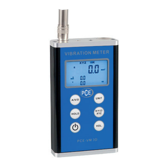
Vibration Meter
PCE-VM 3D
IN S T R U C T IO N M A N U A L
Advertisement
Table of Contents

Related Manuals for PCE Americas PCE-VM 3D


Summary of Contents for PCE Americas PCE-VM 3D
- Page 1 PCE Americas Inc. PCE Instruments UK Ltd. 711 Commerce Way Units 12/13 Suite 8 Southpoint Business Park Jupiter Ensign way FL-33458 Hampshire / Southampton United Kingdom, SO31 4RF From outside US: +1 From outside UK: +44 Tel: (561) 320-9162 Tel: (0) 2380 98703 0...
-
Page 2: Technical Parameters
1. FEATURES * Uses piezoelectric acceleration transducer to convert vibration signal. * In accordance with ISO 2954,GB13823.3, used for periodic measurements, to detect out-of-balance,misalignment and other mechanical faults in rotating machines. * Specially designed for easy on site vibration measurement of all rotating machinery for quality control, commissioning, and predictive maintenance purposes. -
Page 3: Parts Introduction
3. PARTS INTRODUCTION Figure 3.1 3-1 Main Body 3-4 3D Vibration Sensor 3-2 Stinger Probe (Cone) 3-5 Bolt 3-3 Stinger Probe (Ball) 3-6 Magnetic Base According to different situations, the transducers maybe fixed in the probe or connected to the magnetic base. (see chapter 4 in detail) 4. - Page 4 4.1 Installation Principle The testing position should show the vibration characters of the object to be tested. The main axis of the transducers should be consistent with the direction of the object to be tested The sensor should be in close contact with the object to be tested. 4.2 Install Method Method Install with...
- Page 5 4.2.2 Installed With Magnetic Base Application range: Magnetic, flat surface, roughness less than Ra1.6, acceleration less than 20m/ . Usage: connect the vibration sensor with magnetic base with the M5 bolt included. And then place the magnetic base to the object to be tested. Please refer the below.
-
Page 6: Getting Started
5. GETTING STARTED 5.1 Connecting the sensor a. Note that this meter accepts only the supplied vibration sensor. b. Plug the connector side of the sensor into the plug at the top of the meter. c. The sensor can be connected to the machinery under test in three ways. Please refer the blow. - Page 7 FUNCTION UNIT NOTE millimeters per second mm/s (RMS) inch/s inches per second Inch/s meter per second squared g-force (Peak) feet per second squared ft/s millimeters DISP (Peak-Peak) one thousandth of an inch 5.6 MAX HOLD To freeze maximum values, just press the Hold key, a symbol ‘Max’ shows on the display.
- Page 8 times, causing costly production down time. As parts of mechanical equipment wear and deteriorate, the equipment vibration increases. Monitoring the vibration of healthy mechanical equipment on an ongoing bas is, detects any deterioration long before it becomes a critical problem, allowing spares to be ordered in advance and maintenance to be planned only when necessary.
-
Page 9: Battery Replacement
6.3 Measurement Techniques In general, vibration of anti-friction bearings is best monitored in the load zone of the bearing. Equipment design often limits the ability to collect data in this zone. Simply select the Measurement Point which gives the best signal. Avoid painted surfaces, unloaded bearing zones, housing splits, and structural gaps. - Page 10 Note: (1)“Class I” is small motor ( power less than 15 kw). “Class II” is medium motor (power between 15 ~75kw). “Class III” is high power motor (hard base). “Class IIII” is high power motor (stretch base). (2)A,B,C,D are vibration Rank. “A” means good, “B” means satisfying, “C” means not satisfying, “D”...
-
Page 11: Troubleshooting
E. Troubleshooting Vibration Most possible Other possible reason Note frequency reason 1. Eccentric of gear, belt sheave and bush. 2. Shaft is not in the middle Synchronous or curving (if vibration on Imbalance the shaft direction is high). with 3. Belt fault 4.
Need help?
Do you have a question about the PCE-VM 3D and is the answer not in the manual?
Questions and answers