Table of Contents
Advertisement
Quick Links
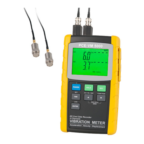
SD card real time data recorder, RS232/USB
4 Channels
Vibration Analyzer
PCE-VM 5000
OPERATION MANUAL
PCE Americas Inc.
711 Commerce Way
Suite 8
Jupiter
FL-33458
USA
From outside US: +1
Tel: (561) 320-9162
Fax: (561) 320-9176
info@pce-americas.com
www.pce-instruments.com/english
www.pce-instruments.com
Your purchase of this
4
C H A N N E L S
VIBRATION
METER
with SD CARD DATA
RECORDER marks a
step forward for you
into
the
field
p r e c i s i o n
measurement.
Although this METER
is
a
complex
delicate
instrument,
its durable structure
will allow many years
of
use
if
proper
operating
techniques
are developed. Please
read
the
following
instructions
carefully
and always keep this
manual
within
reach.
PCE Instruments UK Ltd.
Units 12/13
Southpoint Business Park
Ensign way
Hampshire / Southampton
United Kingdom, SO31 4RF
From outside UK: +44
Tel: (0) 2380 98703 0
Fax: (0) 2380 98703 9
info@pce-instruments.com
of
and
easy
Advertisement
Table of Contents

Related Manuals for PCE Americas PCE-VM 5000


Summary of Contents for PCE Americas PCE-VM 5000
- Page 1 PCE Americas Inc. PCE Instruments UK Ltd. 711 Commerce Way Units 12/13 Suite 8 Southpoint Business Park Jupiter Ensign way FL-33458 Hampshire / Southampton United Kingdom, SO31 4RF From outside US: +1 From outside UK: +44 SD card real time data recorder, RS232/USB...
-
Page 2: Table Of Contents
TABLE OF CONTENTS 1. FEATURES................ 1 2. SPECIFICATIONS.............. 2 3. FRONT PANEL DESCRIPTION..........9 4. MEASURING PROCEDURE..........11 4-1 Preparation..............11 4-2 Unit selection ( Acc./Velocity/Displacement selection )..............12 4-3 Function selection ............14 4-4 Zero adjustment, Max hold reset procedures....15 4-5 Data Hold..............16 4-6 Data Record ( Max./ Min. -
Page 3: Features
1. FEATURES * 4 channels vibration recorder, use SD card to save the 4 channels' data along with time information, paperless. * Applications for industrial vibration monitoring : All industrial machinery vibrates. The level of vibration is a useful guide to machine condition. Poor balance, misalignment &... -
Page 4: Specifications
* Innovation and easy operation, computer is not need to setup extra software, after execute datalogger, just take away the SD card from the meter and plug in the SD card into the computer, it can down load the all the measured value with the time information ( year/month/date/ hour/minute/second ) to the Excel directly, then user can make the further data or graphic... - Page 5 Function Acceleration, Velocity : RMS, Peak, Max Hold. Displacement : p-p ( peak-peak ), Max Hold p-p. Unit Measurement Metric Imperial Acceleration meter/s^2, g ft/s^2, Velocity mm/s, cm/s inch/s Displacement inch Frequency 10 Hz to 1 KHz * Sensitivity relative during the range the frequency range meet ISO 2954 Refer to table 1, page 30.
- Page 6 Datalogger Auto 1 second to 3600 seconds Sampling Time @ Sampling time can set to 1 second, Setting range but memory data may loss. Manual Push the data logger button once will save data one time. @ Set the sampling time to 0 second.
- Page 7 Power Supply Alkaline or heavy duty DC 1.5 V battery ( UM3, AA ) x 8 PCs, or equivalent. DC 9V adapter input. ( AC/DC power adapter is optional ). Power Current Normal operation ( w/o SD card save data and LCD Backlight is OFF) : Approx.
- Page 8 2-2 Electrical Specifications (23± 5 ℃ Acceleration ( RMS, Peak, Max Hold ) Unit m/s^2 Range 0.5 to 199.9 m/s^2 Resolution 0.1 m/s^2 Accuracy ± ( 5 % + 2 d ) reading @ 160 Hz, 80 Hz, 23 ± 5 ℃ Calibration 50 m/S^2 ( 160 Hz ) Point...
- Page 9 Velocity ( RMS, Peak, Max Hold ) Unit mm/s Range 0.5 to 199.9 mm/s Resolution 0. 1 mm/s Accuracy ± ( 5 % + 2 d ) reading @ 160 Hz, 80 Hz, 23 ± 5 ℃ Calibration 50 mm/s ( 160 Hz ) Point Unit cm/s...
- Page 10 Displacement ( p-p, Max Hold p-p ) Unit Range 1.999 mm Resolution 0.001 mm Accuracy ± ( 5 % + 2 d ) reading @ 160 Hz, 80 Hz, 23 ± 5 ℃ Calibration 0.141 mm ( 160 Hz ) Point Unit inch...
-
Page 11: Front Panel Description
3. FRONT PANEL DESCRIPTION Fig. 1... - Page 12 3-1 Display 3-2 Power Button ( Backlight Button ) 3-3 Hold Button 3-4 REC Button 3-5 ACC/VEL/DISP Button ( Button ) ▲ 3-6 SET Button ( Time Button ) 3-7 FUNCTION Button ( Button ) ▼ 3-8 LOG Button ( ENTER Button ) 3-9A CH1 VB-83 Input Socket 3-9B CH2 VB-83 Input Socket 3-9C CH3 VB-83 Input Socket...
-
Page 13: Measuring Procedure
4. MEASURING PROCEDURE 4-1 Preparation 1)Install the vibration sensor set The complete vibration set are : 1. Vibration Sensor, 3-18, Fig 2 2. Sensor Cable, 3-21, Fig. 2 3 VB-83 module, 3-24, Fig. 2 * Plug in the " Cable BNC Plug " ( 3-22, Fig. -
Page 14: Unit Selection ( Acc./Velocity/Displacement Selection )
2) 1) Power on the meter by pressing the " Power button " ( 3-2, Fig. 1 ) > 3 seconds continuously. * After already power on the meter, pressing the " Power button " > 3 seconds continuously will turn off the meter. - Page 15 Measurement Unit Metric unit Acceleration m/s^2, g Imperial unit ft/s^2 * LCD show " ACC " Metric unit Velocity mm/s, cm/s Imperial unit inch/s * LCD show " VEL. " Metric unit Displacement Imperial unit inch. * LCD show " DISP p-p" m/s^2 Metric unit...
-
Page 16: Function Selection
4-3 Function selection Select the desired function ( RMS, Peak, Max HOLD ) by pressing the " Function Button " ( 3-7, Fig. 1 ). continuously ( not release the button ), until the Display will show the desiring function ( RMS, Max HOLD, Peak ) , then release the "... -
Page 17: Zero Adjustment, Max Hold Reset Procedures
4-4 Zero adjustment, Max hold reset procedures Zero adjustment procedures Due to drift of environment temperature value, battery power change, meter used for a long time or other reasons. The display value may exist not zero value ( few digits ) in case of no signal into the " Vibration Sensor ". General speaking those not zero value will not effect the measurement typically. -
Page 18: Data Hold
* Press the " SET Button " ( 3-6, Fig. 1 ) to select the channel no. ( CH2, CH3, CH4 ), after the exact channel is selected, the channel no. will flashing . Press " Enter Button " ( 3-8, Fig. 1 ) to clear the existing Max hold value according the selected channle no. -
Page 19: Datalogger
5. DATALOGGER 5-1 Preparation before execute datalogger function a. Insert the SD card Prepare a " SD memory card " ( 1 G to 16 G, optional ), insert the SD card into the " SD card socket " ( 3-10, Fig. 1). The front panel of the SD card should face against the the down case. -
Page 20: Auto Datalogger ( Set Sampling Time ≧ 1 Second )
5-2 Auto Datalogger ( Set sampling time 1 second ) ≧ a. Start the datalogger Press the " LOG Button ( 3-8, Fig. 1 ) > 3 seconds continuously, the lower LCD will show the " LOGGER " indicator and flashing per sampling time, at the same time the measuring data along the time information will be saved into the memory circuit. -
Page 21: Manual Datalogger ( Set Sampling Time = 0 Second )
5-3 Manual Datalogger ( Set sampling time = 0 second ) a. Set sampling time is to 0 second Press the " LOG Button ( 3-8, Fig. 1 ) once , the low LCD will show the indicator " LOGGER ", then press the " LOG Button "... -
Page 22: Check Sampling Time Information
5-5 SD Card Data structure 1) When the SD card is used into the meter, the SD card When the first time, the SD card is used into the meter, the SD card will generate a folder : VBC01 2)If the first time to execute the Datalogger, under the route VBC01\, will generate a new file name VBC01001.XLS. -
Page 23: Saving Data From The Sd Card To The Computer
6. Saving data from the SD card to the computer ( EXCEL software ) 1) After execute the Data Logger function, take away the SD card out from the " SD card socket " ( 3-10, Fig. 1 ). 2) Plug in the SD card into the Computer's SD card slot ( if your computer build in this installation ) or insert the SD card into the "... -
Page 24: Advanced Setting
EXCEL graphic screen ( for example ) 7. ADVANCED SETTING Under do not execute the Datalogger function, press the " SET Button " ( 3-6, Fig. 1 ) continuously at least 3 seconds will enter the " Advanced Setting " mode. then press the "... -
Page 25: Set Clock Time ( Year/Month/Date, Hour/Minute/ Second )
Remark : During execute the " Advanced Setting " function, if press " SET Button " ( 3-6, Fig. 1 ) > 3 seconds will exit the " Advanced Setting " function, the LCD will return to normal screen. 7-1 Set clock time ( Year/Month/Date, Hour/Minute/ Second ) When the lower display show "... -
Page 26: Set Sampling Time
7-2 Set sampling time ( SecondS ) When the lower display show " SP-t " 1) Use the " Button " ( 3-5, Fig. 1 ) or " Button " ( ▲ ▼ 3-7, Fig. 1 ) to adjust the value ( 0, 1, 2, 5, 10, 30,60, 120, 300, 600, 1800,3600 seconds ). -
Page 27: Decimal Point Of Sd Card Setting
yES - Meter's beep sound will be ON with default. no - Meter's beep sound will be OFF with default. is power ON. 2)After select the upper text to " yES " or " no ", press the " ENTER Button " ( 3-8, Fig. 1 ) will save the setting function with default. -
Page 28: Set Metric/Imperial Unit
yES - Intend to format the SD memory card no - Not execute the SD memory card format 2)If select the upper to " yES ", press the " Enter Button " ( 3-8, Fig. 1 ) once again, the Display will show text "... -
Page 29: Battery Replacement
9. BATTERY REPLACEMENT 1)When the left corner of LCD display show " ", it is necessary to replace the battery. However, in-spec. measurement may still be made for several hours after low battery indicator appears before the instrument become inaccurate. 2)Loose the screws of the "... - Page 30 The data output is a 16 digit stream which can be utilized for user's specific application. A RS232 lead with the following connection will be required to link the instrument with the PC serial port. Meter (9W 'D" Connector) Center Pin......Pin 4 (3.5 mm jack plug) Ground/shield.......Pin 2 2.2 K...
-
Page 31: Classification Ranges
D8 to D1 Display reading, D1 = LSD, D8 = MSD For example : If the display reading is 1234, then D8 to D1 is : 00001234 End Word RS232 FORMAT : 9600, N, 8, 1 Baud rate 9600 Parity No parity Data bit no. -
Page 32: Sensitivity Relative According Iso 2954
Large machines on heavy foundations ( Group G ) Good 0 to 1.80 mm/s Acceptable 1.81 to 4.50 mm/s Still permissible 4.51 to 11.2 mm/s Dangerous > 11.2 mm/s Largest machines and turbo machines with a special foundations ( Group T ). Good 0 to 2.80 mm/s Acceptable... -
Page 33: Patent
14. PATENT The meter ( SD card structure ) already get patent or patent pending in following countries : Germany JAPAN Nr. 20 2008 016 337.4 TAIWAN 3151214 M 358970 CHINA M 359043 ZL 2008 2 0189918.5 ZL 2008 2 0189917.0 Patent pending...
Need help?
Do you have a question about the PCE-VM 5000 and is the answer not in the manual?
Questions and answers