Sign In
Upload
Manuals
Brands
Tektronix Manuals
Measuring Instruments
DC503a
Tektronix DC503a Manuals
Manuals and User Guides for Tektronix DC503a. We have
1
Tektronix DC503a manual available for free PDF download: Instruction Manual
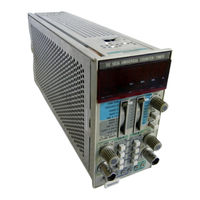
Tektronix DC503a Instruction Manual (300 pages)
Universal Counter/Timer
Brand:
Tektronix
| Category:
Measuring Instruments
| Size: 24 MB
Table of Contents
Table of Contents
4
List of Illustrations
8
Operators Safety Summary
10
Service Safety Summary
11
Specification
17
Instrument Description
17
Instrument Options
17
Standard Accessories
17
Performance Conditions
17
Electrical Characteristics
18
Miscellaneous
23
Environmental
23
Physical Characteristics
24
Section 2 OPERATING INSTRUCTIONS
25
Introduction
25
Installation and Removal
25
Controls and Connectors
26
Display and Unit Indicators
26
Functions
28
Channel a Input and Level Functions
28
Input Considerations
28
Input Sources
28
Input Coupling
28
Attenuators and Maximum Input Volts
28
Sensitivity and Frequency Range
28
Slope and Level
28
Operators Familiarization
29
Preparation
29
Display Tests
29
Readout Segment Test
29
Frequency a Displays
29
Period B, Width B, Andtimea -- B
29
Displays
29
OPERATING INSTRUCTIONS (Cont)
29
Events a During B and Ratio A/B Displays
30
Time Manual Displays
30
Totalize a Display
30
Channel a Slope
31
Channel B Slope
31
Operating Modes
31
General
31
Frequency a Mode
32
Period Modes
32
Time Interval Modes
32
Events a During B Mode
34
Ratio Mode
34
Time Manual Mode
35
Totalize a Mode
36
Repackaging for Shipment
36
Introduction
37
Installation Et Retrait
37
Indicateurs D'affichage Et D'unites
38
Selection du Mode D'utilisation Et Roles des Commander
38
Entree de la Vole a Et Fonctions de Niveau
40
Description des Entrees
40
Sources
40
Couplage
40
Attenuateurs Et Tensions D'entree Maximales
40
Sensibilite Et Plage de Fr~Quence
40
Pente Et Niveau de Declenchement
40
Familiarisation de I'utilisateur Avec I'appareil
41
Tests de I'affichage
41
Test des Segments de 1'Affichage
41
Affichage de la Mesure de la Fr~Quence a
41
Affichage des Mesures de la P~Riode B, de la Largeur B Et du Temps a -> B
42
Affichage du Nombre D'~V~Ne" Ments Presents Sur a Durant B Et du Rapport A/B
42
Affichage de la Mesure Manuelle de Temps
42
Pente de la Vole a
43
Modes D'utilisation
43
G~N~Ralit~S
43
Mesure de P~Riode
44
Temps
46
Mode «Mesure du Rapport
47
Mode «Mesure de la Totalisation a
48
Instructions de R~Emballage Pour Expedition
48
Installation and Auswechseln
49
Bedienungselemente and Stecker
50
Darstellung and Anzeige
50
Wahl der Betriebsarten
50
Signaleingang
52
Eingangsquellen
52
Eingangskoppelung
52
Empfindlichkeit and Frequenzbereich
52
Flanke and Pegel
52
Vorbereitung
53
Periodendauer B, Pulsbreite B
53
Manuelle Zeitdarstellung
54
Darstellung Summe a
54
Flanke Kanal a
55
Flanke Kanal B
55
Betriebsarten
55
Frequenz A-Betrieb
55
Periodendauermessungen
56
Zeitintervallmessungen
56
Ereignisse a W~Hrend B
58
Manuelle Zeitmessungen
59
Summierung a
60
Verpackung des Ger~Tes
60
T-~ Z
64
- I
64
2~Fi
68
The Following Servicing Instructions
73
Section 3 THEORY of OPERATION
74
Block Diagram Description
74
Introduction
74
Channel a and B Amplifiers
74
FREQUENCY a (Variable Gate)
74
PERIOD B (Variable Clock)
74
PERIOD B (Averageable-100 Ns Clock)
74
WIDTH B (Variable Clock)
74
WIDTH B (Averageable-100 Ns Clock)
74
TIME a - B (Variable Clock)
75
TIME MANUAL (Variable Clock)
75
TIME a -- B (Averageable-100 Ns Clock)
75
EVENTS a DURING B (Averageable)
75
RATIO A/B (Averageable)
75
Decimal Point and Annunicator Encoder
75
Totalize a
75
Decade Accumulators, 6_Decade
75
Measurement Cycle Timing
75
Time Base
76
Power Supplies
76
Detailed Circuit Description
76
Introduction
76
CH a and CH Amplifiers
76
Introduction to Signal Routing
77
Time a ~ B Generator
77
Signal Routin and Gate Generator 3
77
N Circuit
80
Measurement Cycle Timin .5O
81
Decade Accumulators
82
Counter
83
Display
83
Switching Logic
83
Avgs/Timing)
83
Time Base 10
84
Power Supplies
84
Test Equipment Required
85
Services Available
85
Performance Check Procedure
85
Calibration Interval
85
Introduction
85
Section 4 CALIBRATION
85
Time Base Checks
87
CH a and CH B Checks
87
Check Set-Up for Low Frequency Ac and Do Sensitivity
90
Minimum Pulse Width Checks
91
Two Channel Function Checks
94
Trigger Level Checks
95
Rear Interface Checks
97
Adjustment Procedure
99
Introduction
99
Test Equipment Required
99
Preparation
99
Section S MAINTENANCE
101
General Maintenance Information
101
Static-Sensitive Components
101
Cleaning
101
Obtaining Replacement Parts
102
Soldering Techniques
102
Semiconductors
103
Interconnecting Pins
103
Square Pin Assemblies
103
Circuit Board Pins and Ferrules
103
Dual Entry Circuit Board Pin Sockets
104
Bottom Entry Circuit Board Pin Sockets
104
Multipin Connectors
104
Switch Maintenance
105
Front Panel Latch Removal
105
Rear Interface Information
106
Functions Available at Rear Connector
106
Option 01
109
Fig
170
Triggering Circuitresponsetoimproper(A)
183
Illustration Ofch a Events Counted from Portion of CH a Signal Pulses During the Counter Gate Open Time (Controlled by the CH B Signal)
183
Typical DC 503A Timing Diagram
183
Typical Square Pin Assembly
183
Exploded View of Circuit Board Pin and Ferrule
183
Dual Entry Circuit Board Pin Socket
183
Bottom Entry Circuit Board Pin Socket
183
Orientation and Disassembly of Multipin Connectors
183
Rear Frame Removal
183
Circuit Board Removal
183
Electrical Characteristics
184
Miscellaneous
184
Environmental
184
Physical Characteristics
184
Gate Time Vs Measurement Resolution
184
Plug-In Installation/Removal
195
Controls and Connectors
197
Frequency a Display Check
199
Period B, Time a - B, Width B (Timing Mode) Display Check
200
Period B, Time a ~ B, Width B (Averaging Mode) Display Check
200
Period B, Time A- B, Width B (Averaging Mode) Display Check
200
Ratio A/B and Events Aduring B Display Check
200
Period B, Time A-B, Width B (Timing Mode)
200
Display Check
200
Representation of Interval Measurements
203
Typical CH a and CH B Level out Voltage Settings for Various Time Interval Measurements
204
Theory of Operation
207
PROM Selection Code
216
List of Test Equipment Requirements
219
Check Set-Up for the High Frequency Sensitivity Using X1 and X5 Attenuation
221
Check Set-Up for Minimum Pulse Width Signals
225
Check Set-Up for Trigger Level Range
229
Damage
234
Advertisement
Advertisement
Related Products
Tektronix DC5010
Tektronix DC 501
Tektronix DCM300
Tektronix DCM320
Tektronix DCM330
Tektronix DCM910
Tektronix DTM520
Tektronix DSA 600 Series
Tektronix DSA 602A
Tektronix DMA 120
Tektronix Categories
Test Equipment
Measuring Instruments
Amplifier
Portable Generator
Printer
More Tektronix Manuals
Login
Sign In
OR
Sign in with Facebook
Sign in with Google
Upload manual
Upload from disk
Upload from URL