
Related Manuals for Extech Instruments 382090


Summary of Contents for Extech Instruments 382090
- Page 1 User's Guide 1000A 3-Phase Power Analyzer/Datalogger Model 382090 (60Hz) Model 382091 (50Hz)
-
Page 2: Warranty
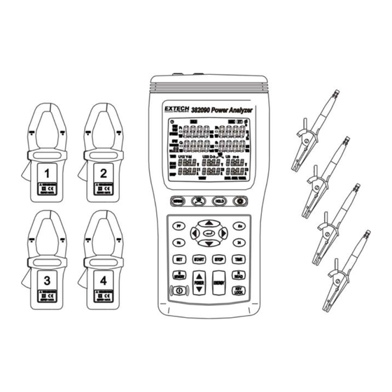
Introduction Congratulations on your purchase of the Extech 382090/382091 1000A 3-Phase Power Analyzer Datalogger. Model 382090 is for use with 60Hz power systems. Model 382091 is for use with 50Hz power systems. This package includes four (4) clamp-on meters and four (4) alligator clip leads that connect to the analyzer/datalogger. - Page 3 Safety This Operation Manual provides information and warnings essential for operating the Model 382090/382091 in a safe manner. Before using this meter, be sure to carefully read the following safety information. DANGER During high voltage measurements, incorrect measurement procedures could result in injury or death, as well as damage to the meter.
- Page 4 Always set up the measurement first and then connect test leads to the circuit. • Make connections to the meter first, before connecting leads to a live circuit. • Connect the ground lead first, then the voltage leads and the current probe. Disconnect in reverse order. 382090 382091 V4.0 09/07...
-
Page 5: Analyzer Description
Analyzer Description 382090 382091 V4.0 09/07... - Page 6 POWER Press to display the measured power. Use this button to cycle through the Pt123, Qt123 and St123 displays 22. ENERGY Press to display the total integrated power energy 23. KEY Lock Press to lock all of the keys except the keys Power on-off key 382090 382091 V4.0 09/07...
-
Page 7: Display Description
DATA M ××: Auto datalogging indicator; M flashes each time a data set is recorded. 01 ~ 10: Memory blocks (20,000 max. data sets can be stored) FF: Memory full indicator (when 10 memory blocks or 20,000 readings are filled) 382090 382091 V4.0 09/07... - Page 8 U1, V, A, U2, V, A, U3, V, A: Three-phase, four-wire (3P4W) U1, U2, U3 voltage and I1, I2, I3 current measurement V: Voltage unit of measure A: Current unit of measure (ampere) 1000V: Voltage range indication 250A, 500A, 1000A: Current range indication (Autoranging) 382090 382091 V4.0 09/07...
-
Page 9: Operation
Connect the red voltage test lead to the “U1” terminal. Connect the I1 current probe output plug to the “I1” jack. To measure ground leakage current, connect the I4 current probe output plug to the “I4” jack. 382090 382091 V4.0 09/07... - Page 10 The energy integration value and the current time will continually update. Press the “ ↵ ” key to pause the energy calculation; the HOLD annunciator will display. Press the HOLD key to exit the energy measurement mode. 382090 382091 V4.0 09/07...
- Page 11 To measure ground leakage current, press the I4 current probe trigger to open the jaw and then fully enclose the ground line “G”. 5. Use the POWER key to select (P1, Q1, S1, PF1), (P2, Q2, S2, PF2) and (Pt, Qt, St, PFt). 382090 382091 V4.0 09/07...
- Page 12 The energy integration value and the current time will be continually updated, press the “ ↵ ” key to pause the energy calculation; the HOLD annunciator will display. Press HOLD to exit the energy measurement mode. 382090 382091 V4.0 09/07...
- Page 13 Press the I2 current probe trigger to open the jaw, and then fully enclose the Line “C”. 5. Use the POWER key to select (P1, Q1, S1, PF1), (P2, Q2, S2, PF2) & (Pt, Qt, St, PFt) 382090 382091 V4.0 09/07...
- Page 14 The energy integration value and the current time will continually update, press “ ↵ ” key to pause the energy calculation; the HOLD annunciator will display. Press HOLD to exit the energy measurement mode. 382090 382091 V4.0 09/07...
- Page 15 Press the I2 current probe trigger to open the jaw and then fully enclose Line “B”. Press the I3 current probe trigger to open the jaw and fully enclose Line “C”. Press the I4 current probe trigger to open the jaw and fully enclose neutral line “N”. 382090 382091 V4.0 09/07...
- Page 16 4. Press the I4 current probe trigger to open the jaw and then fully enclose the desired measured wire. 5. Read the I4 value, if the measured current value is greater than 250A, the “OL” symbol will appear. 382090 382091 V4.0 09/07...
- Page 17 4. When the maximum block or maximum reading limit is reached, the “FF” annunciator will be displayed and datalogging will stop. Downloading Data to a PC Please refer to the software operation section for data download instructions.. 382090 382091 V4.0 09/07...
- Page 18 ” will switch off indicating Auto Power off is disabled. 2. The Auto power off mode is enabled each time the meter is turned on. It is automatically disabled in the following modes: ENERGY mode Automatic datalogging When Meter is connected to PC 382090 382091 V4.0 09/07...
-
Page 19: Software Operation
RS-232 PC Interface Connect the Optical Interface connector to the 382090 Power Analyzer (middle pin is keyed for correct orientation). Connect the 9-pin female connector to the 9-pin serial PC port (COM1 or COM2). PC Requirements • 486-33 IBM compatible PC or better •... -
Page 20: Specifications
Note – Examples include switches in the fixed installation and some equipment for industrial use with permanent connection to the fixed installation. MEASUREMENT CATEGORY IV: Equipment of OVERVOLTAGE CATEGORY IV is for use at the origin of the installation. Note – Examples include electricity meters and primary over-current protection equipment 382090 382091 V4.0 09/07... - Page 21 • Displays: Reactive power of each channel and the sum of multiple channels. • Polarity display: For phase lag (LAG) current is behind voltage: No symbol. For LEAD phase (LEAD: current ahead of voltage): “-” sign 382090 382091 V4.0 09/07...
- Page 22 Timer Accuracy accuracy 3.999KVAh 0.001KVAh 39.99KVAh 0.01KVAh 399.9KVAh 0.1KVAh ± 50ppm at 77 ± (1.5%rdg + 20d) 1 sec 3.999MVAh 0.001MVAh 39.99MVAh 0.01MVAh 119.3MVAh 0.1MVAh • Measurement display: Displays total apparent power energy (sum of absolute values). 382090 382091 V4.0 09/07...
- Page 23 Safety CAT III 600V per IEC61010-1, Pollution Degree2. : IEC 61010-1 2nd Edition and IEC61010-2-032 Voltage Test Leads (4pcs) Safety CAT III, 1000V, AC 10A Max Alligator Clips (4pcs) Safety CAT III, 1000V, AC 10A Max 382090 382091 V4.0 09/07...
-
Page 24: Maintenance
Tech support: Ext. 200; Email: support@extech.com Repair/Returns: Ext. 210; Email: repair@extech.com Website: www.extech.com Copyright © 2004 Extech Instruments Corporation All rights reserved including the right of reproduction in whole or in part in any form. more infor for Extech 382090 Phone: 01235 838 555 Email: cs@airconcern.co.uk...
Need help?
Do you have a question about the 382090 and is the answer not in the manual?
Questions and answers