Cattani turbo smart Operator's Handbook Manual
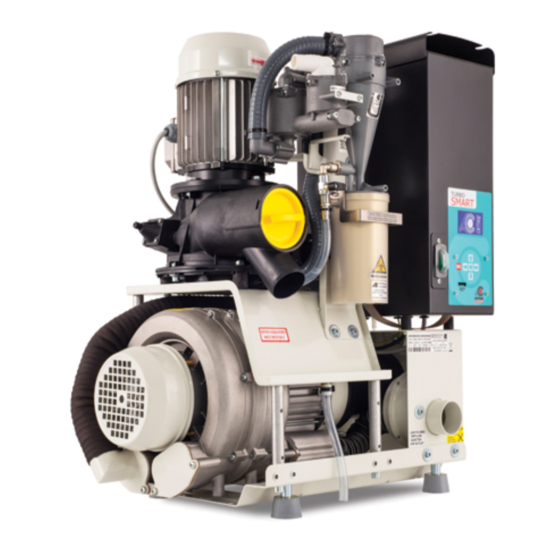
Universal aspirator
Hide thumbs
Also See for turbo smart:
- Operator's handbook manual (99 pages) ,
- Instruction manual (64 pages) ,
- User maintenance manual (16 pages)

Related Manuals for Cattani turbo smart


Summary of Contents for Cattani turbo smart
- Page 1 MANUALE ISTRUZIONI OPERATOR’S HANDBOOK MANUEL D’UTILISATION GEBRAUCHSANWEISUNG MANUAL DE ISTRUCCIONES T U R B O A UNIVERSAL ASPIRATOR...
-
Page 3: Avvisi Importanti
T U R B O A UNIVERSAL ASPIRATOR INDICE Dati generali di funzionamento 50/60 Hz .................2 Introduzione ........................3 Segnali ed avvisi .......................3 Montaggio e messa in funzione ..................4 Manutenzione ordinaria ....................8 Manutenzione straordinaria ....................9 Istruzioni per muoversi e modifi care alcuni parametri nei menù di Turbo-Smart ....10 Istruzioni per settare la comunicazione Zig-bee (wireless) ..........17 Descrizione allarmi ......................22 Avvisi importanti ......................23... -
Page 4: Dati Generali Di Funzionamento 50/60 Hz
• Dati generali di funzionamento 50/60 Hz Aspiratore ad uso dentistico Turbo-Smart Modello Turbo-Smart “A” Turbo-Smart “B” Tensione nominale 230 V 230 V Frequenza nominale 50/60 Hz 50/60 Hz Corrente nominale Modalità di impiego Funzionamento Funzionamento continuo continuo Protezione contro l’umidità Comune Comune Potenza massima assorbita... -
Page 5: Table Of Contents
T U R B O A UNIVERSAL ASPIRATOR INDEX General 50/60 Hz running data..................26 Introduction ........................27 Signals and warnings .....................27 Installation and starting ....................28 Routine maintenance .....................32 Extraordinary maintenance ....................33 Instructions to navigate Turbo-Smart menus and to modify some parameters ....34 Instructions for communication settings Zigbee (wireless) ..........41 Alarms description ......................46 Important notices ......................47... -
Page 6: General 50/60 Hz Running Data
• General 50/60 Hz running data Turbo-Smart dental aspirator Model Turbo-Smart “A” Turbo-Smart “B” Rated voltage 230 V 230 V Rated frequency 50/60 Hz 50/60 Hz Rated current Operating conditions Continuous Continuous operation operation Protection against Ordinary Ordinary ingress of liquids Max. -
Page 7: Introduction
This manual should be always available for consultation during unpacking, use, installation and starting of Turbo-Smart. Our updated manuals are available on the web site www.cattani.it. We recommend their consul- tation especially for updates about safety. • Signals and warnings •... -
Page 8: Installation And Starting
• Installation and starting • Recommended precautions HANDLE WITH CARE WARNING WARNING Before unpacking the appliance, check the warning shock- SHOCKWATCH watch on the carton. In case of it being red or the carton RED INDICATES ROUGH HANDLING IF RED, NOTE ON BILL OF LADING being damaged, accept the material reserving the right to INSPECTION MAY BE WARRANTED examine the machine. - Page 9 • Installation Before connecting the aspirator to the piping of the cen- tralized system, ascertain that aspiration piping is clean as heavy debris could damage the appliances. Connect the PVC light grey aspiration tube (2b) (supplied with the machine) to the 50 mm Ø tube-holder (2) (“aspirated fl uid inlet”).
- Page 10 • Installation in parallel It is advisable to install in parallel only machines with the same fl ow and head values. With the instal- lation of 2 or 3 Turbo-Smart units in parallel (fi g. F) the total fl ow is doubled or tripled, provided that the diameter of the main piping is increased of 10 mm for each additional aspirator unit.
- Page 11 Starting, fi nal test and users instruction Install and connect the aspirator, select the position ON on the switch, which will light up after one of the dental units has started working. At this point aspiration will start.To check if Turbo-Smart is working correctly, it is advisable to carry out the dynamic tests (see fi g.
-
Page 12: Routine Maintenance
• Routine maintenance Routine maintenance must be entrusted to specially in- structed surgery staff. • We recommend to pay special attention to all danger si- gnals and to use goggles, gloves and disposable overalls for personal protection. Daily ALLARME: • Check for any possible alarm on the display. In case of TEMPERATURA ELEVATA alarms, contact the technician. -
Page 13: Extraordinary Maintenance
• Extraordinary maintenance Extraordinary maintenance must be entrusted to a trained technician in possession of original spare parts: • pay special attention to danger signals. Use goggles, glo- ves and disposable overalls for personal protection; • check that routine maintenance has been duly carried out and make sure that Magnolia products are used;... -
Page 14: Instructions To Navigate Turbo-Smart Menus And To Modify Some Parameters
Main menus When Turbo-Smart is switched on, the display shows the Cattani logo for 10 seconds, after which time the main menu appears. Main Menu “A1” This menu shows some parameters such as: cycles, suc- tion activation time, temperature, presence/absence of the amalgam container and system software release. - Page 15 Secondary Menus Press to enter the Secondary Menus. Pressing the key takes you through the other menus. Drive Status This menu can be accessed without any access password. The display shows useful information about the Turbo- Smart functioning. User Parameters Use the password 0000123000 to enter this menu.
- Page 16 Enter Key to confi rm the password. The cur- sor will disappear. Press to return to the Cattani S.p.A. menu. It is now possible to modify the parameters of the User Parameters menu. Repeat the same process and enter the password 0000456000 to gain access to the System Parameters Se- tup menu.
- Page 17 Drive Status menu This menu can be accessed without any access password. It displays various technical parameters regarding the real- time working conditions of Turbo-Smart. Listed below is the more commonly required information. Blower Output Frequency (max. setting for version A: 85 Hz max.
- Page 18 System Temperature Maximum Detected Temperature (+58 °C: Alarm and Stop of the aspirator) Vacuum (max. setting: 200 mbar) User Parameters menu To access this menu you are required to enter the access password 0000123000 (see instructions on page 36). Vacuum Set Point This is the fi gure to which the unit will limit the vacuum.
- Page 19 Generated Code This code is generated by Cattani S.p.A. Each unit is allocated a unique code. This code needs to be supplied to Cattani to purchase the password (Activation Code) to upgrade version A (2 chair unit) to version B (4 chair unit).
- Page 20 Blower Current Limit (Max. setting for A: 5,5 A Max. setting for B: 7,5 A) Turbo-Smart Off Delay Time (Max. setting: 300 sec. Min. setting: 10 sec.) Pump (Centrifuge) Off Delay Time (Max. setting: 30 sec. Min. setting: 5 sec.) Control Panel Fan Off Delay Time (Default setting: 300 sec.
-
Page 21: Instructions For Communication Settings Zigbee (Wireless)
USB port of the computer and launch the display program. Install the SMART SYSTEM MONITOR program (supplied by Cattani) in the computer. Once the program is launched, the com- pany’s logo will appear for 10 seconds followed by the main menu. - Page 22 Use the dropdown menu to choose which Turbo Smart you want to view. the functional parameters of the Turbo Smart will then be displayed.
- Page 23 Clicking on the SERVICE icon gives access to three different menus, an open one and 2 protected by password. To enter the USER PARAMETERS menu, enter the password 123000 and press OK. In this menu you can change the language, set the desired level of pressure and switch the machine from aspirator for 2 dental units to aspirator for 4 dental units, thanks to an...
- Page 24 In this technical menu you can view and modify all the parameters of the Turbo Smart. The INVERTER STATUS menu, which does not require an access password, displays the functional parameters of the machine while it is in operation. From the main menu, click on the email...
- Page 25 ALERTS box. The full history of all the alarms occurred in the machine during the entire period of operation can be viewed in the EVENT LOG folder. The operation cycles of the Turbo Smart are saved in the ODO COUNTERS menu.
-
Page 26: Alarms Description
• Alarms description Alarm code DESCRIPTION SOLUTION AC80 AC80-07 Microcontroller memory alarm Contact the technician Amalgam level > 95% Replace the amalgam container as soon as possible Amalgam level > 100% Replace the amalgam container Microcontroller memory alarm Contact the technician Short-circuit due to one of the two motors Identify where the short-circuit is coming from and eliminate it... -
Page 27: Important Notices
• Our updated manuals are available on the web site www.cattani.it. We recommend they are consulted especially for updates about safety. - Page 29 • SCHEMA DI MONTAGGIO TURBO-SMART • INSTALLATION LAYOUT MONTAGGIO AL PIANO INSTALLATION ON THE SAME FLOOR OF THE DENTAL UNITS Fig. A Draw. A all’aspiratore to the aspirator MONTAGGIO SOTTOSTANTE INSTALLATION ON A LOWER FLOOR THAN THE ONE OF THE DENTAL UNITS Fig.
- Page 30 • COLLEGAMENTI CIRCUITO INVERTER AC80-07 • INVERTER AC80-07 CONNECTIONS circuito display display circuit fusibili 16 A 16 A fuse SOFFIANTE SEPARATORE BLOWER SEPARATOR fi ltro antidisturbo main fi lter interruttore generale main switch scheda elettronica main board Fig. C Draw. C...
- Page 31 • PROVE DI DIAGNOSI SUI TURBO-SMART • DIAGNOSTIC TESTS ON TURBO-SMART Per verifi care il corretto funzionamento del Turbo-Smart, si possono effettuare alcuni test di tipo dinamico, di seguito esposti. Si dovrà eseguire il test a macchina in funzione e con l’ingresso d’aspirazione libero, non collegato alla tubazione.
- Page 32 • DIAGRAMMA DI LAVORO DI TURBO-SMART • TURBO SMART WORKING DIAGRAM ASPIRAZIONE mbar ASPIRATION mbar 2-VERSIONE "A" e "B"' 2-VERSION “A” and “B” 1- VERSIONE "A" e "B"' 1-VERSION “A” and “B” (666) (1000) (1330) (2000) PORTATA m3/h (l/min) FLOW RATE m3/h 1- CURVA ASPIRAZIONE TURBO-SMART VERSIONE "A"...
- Page 33 TURBO-SMART (versione “B”) TURBO-SMART (version “B”) Fig. F Draw.F TURBO-SMART (versione “A”) TURBO-SMART (version “A”)
- Page 34 • ESPLOSO TURBO SMART • SPLIT-UP DRAWING 023785 023785 025400 025400 015646 015646 043380 Fig. G Cod. 023785 CENTRALINO ELETTRICO ELECTRIC CONTROL PANEL Cod. 025400 SEPARATORE CENTRIFUGO Draw. G CENTRIFUGAL SEPARATOR Cod. 015646 SOFFIANTE BLOWER Cod. 043380 IDROCICLONE HYDROCYCLONE...
- Page 35 • DIMENSIONI TURBO SMART • TURBO SMART DIMENSION Fig. H Draw.H...
- Page 38 ESAM: 1225173 - 1253783 - 0791751 FOREIGN PATENTS OR PATENT APPLICATIONS: CATTANI: AU 546.143 - US 4,386,910 - US 4,787,846 - US 5,039,405 - US 5,002,486 AU 580839 - US 4,684,345 - US 5,330,641 - AT 0040181 - CH 0040181 - DE 0040181...
Need help?
Do you have a question about the turbo smart and is the answer not in the manual?
Questions and answers
Where is the vaccine detecting pipe