Table of Contents
Advertisement
Quick Links
Advertisement
Table of Contents

Related Manuals for EBN X-POS956


Summary of Contents for EBN X-POS956
- Page 1 User’s Manual X-POS956...
-
Page 3: Liability Disclaimer
Copyrights ©2014 All rights reserved. The information in this document is subject to change without prior notice in order to improve reliability, design and function and does not represent a commitment on the part of the manufacturer. This document contains proprietary information protected by copyright. -
Page 4: Table Of Contents
Contents Copyrights ....................... I Liability Disclaimer ....................I Regulatory Information ..................I CE mark compliance ..................I Safety Statement for Lithium Battery ............I Contents ......................... II 1. Hardware Setup ....................1 1.1. Packing Contents .................. 1 1.2. Quick Tour ..................... 2 Front View and Rear View .............. - Page 5 Wait For Drawer Close ............... 59 Beeper/Speaker Configuration ............60 Close Cash Drawer Service ............... 61 5. I/O Definition ....................62 4.1. Power Connector ..........錯誤! 尚未定義書籤。 4.2. Serial Port ............. 錯誤! 尚未定義書籤。 4.3. Cash Drawer ............錯誤! 尚未定義書籤。 6 Specification ..................... 64...
-
Page 7: Hardware Setup
Hardware Setup 1.1. Packing Contents 1. X-POS956 X 1 4. Drive and Utility DVD X 1 2. Power Adapter X 1 3. Power Cord X 1 Chapter 1... -
Page 8: Quick Tour
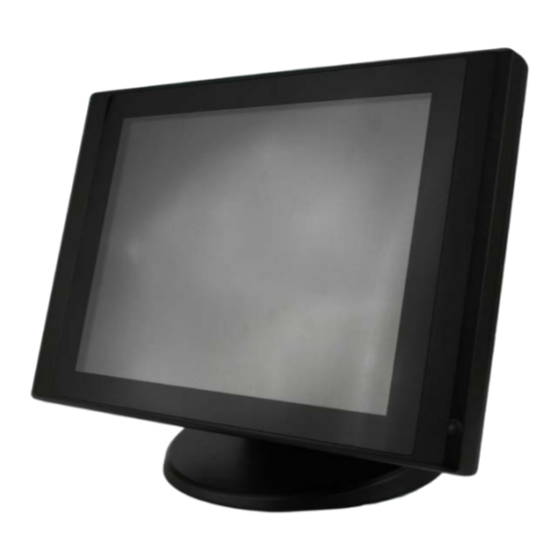
1.2. Quick Tour Front View and Rear View Power indicator LED Indicator The Power indicator will glow green when power is on. Customer Display Mounting Hole Cover MSR Mounting HDD Cover Hole Cover Back Panel I/O Chapter 1... -
Page 9: Basic Peripherals Installation
1.3. Basic Peripherals Installation 1. All cables and wires from peripherals to the POS device are recommended to be fed through the base in the direction as shown below. WARNING: Before the cable cover is removed, please make sure the power is off! Power Adapter Connect the DC cable to the DC in jack. -
Page 10: Usb Odd
USB ODD Connect your USB ODD to USB port. LAN Cable Connect one end of RJ-45 LAN cable to the LAN 1 or LAN 2 port on the back panel of the device, another end to your internet device. Cash Drawer Connect one end of RJ-12 cable to the Cash Drawer port on the back panel of the device, another end to your cash drawer. - Page 11 Caution: Never enable the power supply without the customer display installed and be sure to disable the power supply before removing the customer display. 1. Power up the X-POS956, and press the DEL key to enter BIOS before the Windows screen appear.
- Page 12 2. Under BIOS screen, use the key on your computer keyboard to move to the Advanced tab, and then use the key on your computer keyboard to select Super IO Configuration then press ENTER key. 3. Use the key to highlight the Serial Port 6 Configuration, and the press ENTER key.
- Page 13 4. Use the key to select the COM Voltage, and the press ENTER key. Use the key to highlight 12V and press ENTER key. 5. Press F10 key, highlight Yes and press ENTER key. Chapter 1...
-
Page 14: Msr
1. Remove the two screws fixing the MSR cover. 2. Remove the MSR cover from the device. 3. Connect the connectors of the MSR assembly to the device. 4. Tighten the two M3 screws to fix the MSR assembly. Chapter 1... -
Page 15: 2Nd Display
2nd Display Before installation, make sure that the all item listed below are ready. Base Type 2nd Display Kit: 2nd Display (12” or 15”) base bracket 2nd display base M3 screw X 4 2nd display support M4 screw X 2 Plastic bush VGA Cable Plastic spacer... - Page 16 Base Type 2nd Display Kit Installation: 1. Install the 2nd display base (item B.) onto the X-POS956 by M4 screw X 2 (Item H.) as shown. 2. Insert the plastic bush into the base as shown. Feed the blue connector of the VGA cable (item I.) through the base of the device as shown below.
- Page 17 5. Connect the black head (with power connector) and the power connector of the VGA cable to the VGA port and power input jack of the back I/O panel of the 2nd display, and then tighten the four M3 screws to fix the 2nd display support onto the 2nd display as shown below.
- Page 18 Pole Type 2nd Display Kit Installation: 1. Install the 2nd display base (item D.) onto the X-POS956 by M4 screw X 2 (Item I.) as shown. 2. Insert the plastic bush into the base. Feed the Type A USB connector of the USB cable (item K.) or the blue connector of the VGA cable (item L.) through the...
- Page 19 5. Push the base holder bracket into the base, and then tighten the two M4 screws to fix the 2nd display. 6. Feed the Type B USB connector of the USB cable (item K.) or the black connector of the VGA cable (with power connector) (item L.) through plastic poles (item E.
- Page 20 Display Mount (item B.). 8. Connect the Type B USB connector of the USB cable (item K.) or the black connector of the VGA cable (with power connector) (item L.) to the proper port of the back I/O panel of the 2nd display, and then tighten the four M3 screws to fix the 2nd display mount onto the 2nd display as shown below.
- Page 21 Chapter 1...
- Page 22 2nd Display Power Supply Configuration 1. Power up the X-POS 956, and press the DEL key to enter BIOS before the Windows screen appear. 2. Under BIOS screen, use the key on your computer keyboard to move to the Advanced tab, and then use the key on your computer keyboard to select Video Function Configuration then press ENTER key.
- Page 23 4. Use the key to highlight Enabled and press ENTER key. Chapter 1...
-
Page 24: Turn On The Device
5. Press F10 key, highlight Yes and press ENTER key. 1.4. Turn on the device 1. Make sure all peripherals are connected properly. 2. Press and hold the power switch until the power indicator on the front panel glows green. Chapter 1... -
Page 25: Raid Configuration
RAID Configuration RAID configuration must be done before the Windows operating system (Windows 7 excluded) installation. Before the steps below starts, make sure that an external USB DVD-ROM drive with the Windows installation disc loaded, an external USB floppy disc drive and other accessories are all connected to the X-POS 956 properly. - Page 26 4. Click AHCI/RAID Driver for DOS. 5. A Windows Explore window pops-up. There are two folders: “RAID_F6_32bit_10.1.0.1008_PV” and “RAID_F6_64bit_10.1.0.1008_PV”. Copy a folder into the floppy disc according to the Windows operating system you choose to install. 6. Eject the 3.5” floppy disk and insert it into the USB floppy disk drive which is connected to the X-POS 956.
- Page 27 8. Under BIOS screen, use the key on your external computer keyboard to move to the Advanced tab, and then use the key on your computer keyboard to highlight SATA Configuration and then press the ENTER key. 9. Under Advance tab, highlight SATA Mode and then press the ENTER key of the external computer keyboard.
- Page 28 10. Select RAID Mode or AHCI Mode according to your application, and then press the ENTER key of the external computer keyboard. Chapter 2...
- Page 29 11. Press the F10 key of the external computer keyboard, select Yes and then press the ENTER key of the external computer keyboard. 12. The screen below shows, press the CTRL key and I key of the external computer keyboard simultaneously. Chapter 2...
- Page 30 13. Under the MAIN MENU, select Create RAID Volume and then press ENTER key of the external computer keyboard. 14. Under the CREATE VOLUME MENU, highlight the item Name to specify the volume name. Chapter 2...
- Page 31 15. Highlight the item RAID Level to specify the RAID type (RAID0 or RAID1). 16. Back to the MAIN MENU, select EXIT and then press ENTER key of the external computer keyboard. Chapter 2...
- Page 32 17. Press Y key of the external computer keyboard and then press F11 key to enable the system to reboot by external optical disk drive. 18. The screen below shows and then switches to the Windows installation automatically. Steps below are variable based on the OS you had chosen. Chapter 2...
-
Page 33: For Microsoft Windows Xp
2.1. For Microsoft Windows XP Steps described below are for Microsoft Windows XP series. Press the F6 key of the external computer keyboard as soon as the message on the gray bar shows. Press S key. Chapter 2... - Page 34 If “RAID Mode” is selected under the SATA Configuration in BIOS: Use the key to select Intel (R) Desktop/Workstation/Server Express Chipset SATA RAID Controller. If “AHCI Mode” is selected under the SATA Configuration in BIOS: Use the key to select Intel (R) Desktop/Workstation/Server Express Chipset SATA AHCI Controller.
- Page 35 Press S key to continue. Setup is loading files. Repeat Step 2, Step 3 and Step 4. Chapter 2...
-
Page 36: For Microsoft Windows Embedded Posready
Press ENTER key to continue Windows XP installation. 2.2. For Microsoft Windows Embedded POSReady Steps described below are for Microsoft Windows Embedded POSReady series. 1. When the message on the gray bar shows, press the F6 key of the external computer keyboard. - Page 37 2. Press ENTER key. If “RAID Mode” is selected under the SATA Configuration in BIOS: Use the key to select Intel (R) Desktop/Workstation/Server Express Chipset SATA RAID Controller. Chapter 2...
- Page 38 If “AHCI Mode” is selected under the SATA Configuration in BIOS: Use the key to select Intel (R) Desktop/Workstation/Server Express Chipset SATA AHCI Controller. 4. Press ENTER key to continue. Chapter 2...
-
Page 39: For Microsoft Windows 7、Windows 8
5. On the screen below, select Install Third-Party Storage Drivers. Click Next to continue rest steps of Microsoft Windows Embedded POSReady installation. 2.3. For Microsoft Windows 7、Windows 8 There is not any special configuration or setting for RAID during Microsoft Windows 7 installation. -
Page 40: Basic Driver Installation
Basic Driver Installation 3.1. Before the installation 1. Connect an external USB DVDROM to the USB port and insert the Driver and Utility DVD and turn on the device. The program auto runs and displays the DRIVER BANK screen. 2. On the DRIVER BANK screen, click XPOS 956 Series to enter the driver selection screen. - Page 41 2. Click Next. Chapter 3...
- Page 42 3. Read the License Agreement carefully and click Yes. 4. Click Next. Chapter 3...
-
Page 43: Vga Driver Installation
5. Click Finish. 3.3. VGA Driver Installation 1. On the main screen, click VGA Driver. Chapter 3... - Page 44 2. Please choice your windows OS type. Click VGA Driver for Windows XP, Windows 7, Windows 8, 32bit or 64bit. 3. Click Next. Chapter 3...
- Page 45 4. Click Next. 5. Read the License Agreement carefully and click Yes. Chapter 3...
- Page 46 6. Click Next. 7. Click Next. Chapter 3...
-
Page 47: Touch Screen Driver (Only For Windows Xp)
8. Select restart your computer later to continue with installing the rest of the drivers. Click Finish. 3.4. Touch Screen Driver (Only for Windows XP) Single touch for Windows XP 1. On the driver selection screen, click Touch Panel Driver. Chapter 3... - Page 48 2. Click QM Touch Panel Driver Windows XP 32bit/64bit 3. Click OK. 4. Software Installation - Click Continue Anyway. Chapter 3...
-
Page 49: Lan Driver Installation
5. Hardware Installation - Click Continue Anyway. 6. Click Exit. 3.5. LAN Driver Installation 1. On the main screen, click Realtek LAN Driver Chapter 3... - Page 50 2. Please choice your windows OS type. Click Windows XP, Windows 7, Windows 8, 32bit or 64bit. 3. Click Next button. Chapter 3...
- Page 51 4.Click Install button. 5.Click Finish button. Chapter 3...
-
Page 52: Audio Driver Installation
3.6. Audio Driver Installation 1. On the main screen, click HD Audio Driver. Please choice Windows operating system type. Click Windows XP, Windows 7, Windows 8, 32bit or 64bit. Chapter 3... - Page 53 2. The driver is preparing to install, Click Next button. Chapter 3...
- Page 54 4. Click Yes to restart the Windows. Chapter 3...
-
Page 55: Cash Drawer Driver Installation
3.7. Cash Drawer Driver Installation 1. On the main screen, please Click OPOS Cash drawer sample tool and source code. Click OPOS Cash drawer sample tool, OPOS Cash Drawer sample too source code, Cash drawer user manual, Cash drawer VB/DOS/tool/source code. Chapter 3... - Page 56 Click Next button to install Cash drawer Drver. Chapter 3...
- Page 57 Click Next button Click Install button Click Finish button, if OPOS Common OBJ is necessary, please check the “Insall OPOS CCOS v1.13 Run tome” Chapter 3...
- Page 58 Please wait the OPOS CCO v.1.13 utility initial. Click Next button Chapter 3...
- Page 59 Click Next button Click Next button Chapter 3...
- Page 60 Click Next button Click Next button Chapter 3...
- Page 61 Click the Next button to begin the installation. Please wait the install progress bar finish. Chapter 3...
-
Page 62: Cash Drawer Function Introduction
Click the Finish button to exit the installer. 3.8 Cash Drawer function introduction. Cash Drawer Configuration Before Open Cash Drawer Service, please configure the Cash Drawer configuration. FireTime: It can configuration the voltage pulse timing to open the Cash Drawer. Chapter 3... -
Page 63: Open Cash Drawer Service
Read Status Reverse: If the Cash Drawer is opened, but the Cash Drawer status is closed. Please click “Read Status Reverse” button to change the status from “L” to “H”. Write Status Reverse:If the Cash Drawer cannot open or close, please click the “Write Status Reverse”... -
Page 64: Open Cash Drawer
Open Cash Drawer Click the “Open Cash Drawer” button to open the Cash Drawer box. Cash Drawer Status will update, if the Cash Drawer box is opened. Chapter 3... -
Page 65: Cash Drawer Status
Cash Drawer Status “Check Cash Drawer“ button can re-check the Cash Drawer box status. Cash Drawer Status will show the Cash Drawer box status. Wait For Drawer Close If the Cash Drawer box is opened, click the “Wait For Drawer close” button will be about to begin a beeper/speaker sound. -
Page 66: Beeper/Speaker Configuration
Beeper/Speaker Configuration Beeper configuration If the Cash Drawer box is not closed that out of the “Open Time Out”, the buzzer/speaker Open Time Out: Default is 5000 ms. Beep Frequency: Default is 1000 ms. Beep Duration: Default is 1000 ms. Beep Delay: Default is 1000 ms. -
Page 67: Close Cash Drawer Service
Close Cash Drawer Service Close Cash Drawer Service: It can close the Cash Drawer Service. It can click the “OK” button to exit the OPOS Cash Drawer Test App. Chapter 3... -
Page 68: I/O Definition
I/O Definition Please refer the detailed technical information about all I/O ports as followings. 4.1. Power Connector DC Jack Signal Name +19V +19V GROUND GROUND 4.2. Serial Port COM Port Description Description RI / 5V /12V R232 RS422 RS485 Chapter 5... -
Page 69: Cash Drawer
4.3. Cash Drawer RJ12 Description Description D_OUT0 D_IN Cash Drawer Control Status Address Value Open 280H Bit 4 = 0 Close 280H Bit 4 = 1 Read Status 280H Bit 0 = 0/1 Chapter 4... -
Page 70: Specification
Specification Chapter 5... - Page 71 Main Board Intel® Sandy Bridge LGA1155 Core i3 - 2120 3.3 GHz / L3: 3MB / 2 core / 65 watt Pentium G850 2.9 GHz / L3: 3MB / 2 core / 65 watt Celeron G540 2.5GHz /2 core / 65 watt Chipset Intel®...
Need help?
Do you have a question about the X-POS956 and is the answer not in the manual?
Questions and answers