Table of Contents
Advertisement
Quick Links
Installation, Operation, Repair And Parts Manual
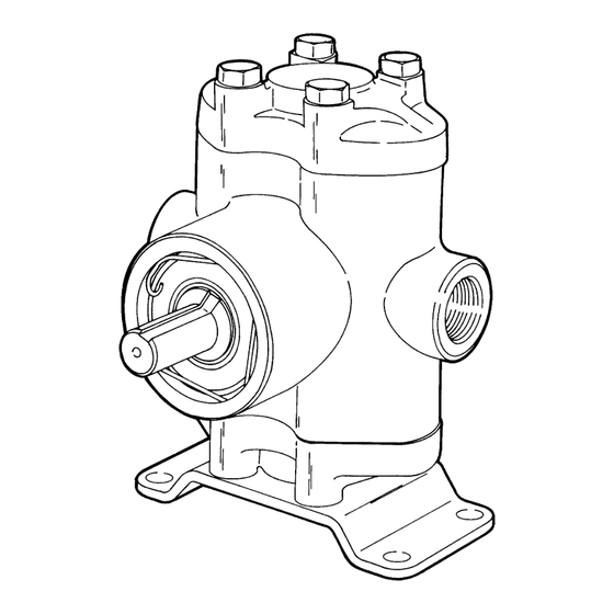
SERIES 5300C-X
Cast Iron Small Twin
Piston Pump
Max. Flow Rate: ..................1.5, 2.0, 2.5
and 3.0 gpm
Max. Pressure: ..........................500 psi
Max. Speed: ............................1725 rpm
Ports: ................................1/2" NPT inlet
1/2" NPT outlet
Max. Operating Temp. ................140 o F
The following special attention notices are used to notify
and advise the user of this product of procedures that
may be dangerous to the user or result in damage to the
product.
NOTE: Notes are used to notify of installation, oper-
ation, or maintenance information that is important
but not safety related.
CAUTION: Caution is used to indicate the presence
of a hazard, which will or can cause minor injury or
property damage if the notice is ignored.
WARNING: Warning denotes that a potential hazard
exists and indicates procedures that must be fol-
lowed exactly to either eliminate or reduce the haz-
ard, and to avoid serious personal injury, or prevent
future safety problems with the product.
DANGER: Danger is used to indicate the presence
of a hazard that will result in severe personal injury,
death, or property damage if the notice is ignored.
Series 5300C-X, 5321C, 5322C and 5324C
Small Twin ® Piston and Plunger Pumps
Description
SERIES 5321C & 5322C
Cast Iron Small Twin
Plunger Pump
Max. Flow Rate: ........................2.2 gpm
Max. Pressure: ........................1000 psi
Max. Speed: ............................1725 rpm
Ports: ................................1/2" NPT inlet
Max. Operating Temp. ................180 o F
Safety Information
Max. Flow Rate: ........................2.9 gpm
Max. Pressure: ..........................800 psi
Max. Speed: ............................1725 rpm
Ports: ................................1/2" NPT inlet
1/2" NPT outlet
Max. Operating Temp. ................140 o F
DANGER: DO NOT pump flammable or explosive
fluids such as gasoline, fuel oil, kerosene, etc. DO
NOT use in explosive atmospheres. The pump
should be used only with liquids compatible with the
pump component materials. Failure to follow this
warning can result in personal injury and/or proper-
ty damage and will void the product warranty.
A pressure relief device, such as an unloader, relief
valve or balancing regulator must be installed on the
outlet side of the pump. Failure to do so could
result in personal injury and/or void the warranty.
•
Be sure all exposed moving parts such as shafts,
couplers and adapters are properly shielded or
guarded and that all coupling devices are securely
attached before applying power.
•
Hollow shaft pumps mounted directly onto power
shaft must be prevented from rotating with the power
shaft by means of a device such as a torque arm.
Pump must float freely on the power shaft and must
not be tied rigidly to equipment on which it is mount-
ed.
Form L-0200P
7/05
SERIES 5324C
Cast Iron Small Twin
Piston Pump
1/2" NPT outlet
Advertisement
Table of Contents

Related Manuals for Hypro SERIES 5300C-X


Summary of Contents for Hypro SERIES 5300C-X
-
Page 1: Safety Information
Series 5300C-X, 5321C, 5322C and 5324C Small Twin ® Piston and Plunger Pumps Form L-0200P Installation, Operation, Repair And Parts Manual 7/05 Description SERIES 5300C-X SERIES 5321C & 5322C SERIES 5324C Cast Iron Small Twin Cast Iron Small Twin Cast Iron Small Twin... - Page 2 This manual will cover the installation of the basic drive Read all instructions and general safety information configurations available for the Hypro Small Twin before attempting to install or operate the pump. Piston and Plunger pumps. Consult the manufacturer...
-
Page 3: System Installation
Direct Drive - Hollow Shaft Installation Hollow shaft models mount directly on the motor or engine shaft (See Figure 4). Adapters are available to convert some solid shaft models for direct shaft mount- ing. After mounting the pump, always turn it by hand to make sure the pump is operating freely. - Page 4 1. Adequate liquid supply. Pump must not run dry for Lubrication Schedule more than 30 seconds. Use a grease gun to lubricate Hypro Series 5300 and 5324 Piston Pumps and Series 5321 and 5322 Plunger 2. Temperature rise. Overheating is harmful to bear- Pumps.
-
Page 5: Repair Instructions
Repair Instructions Recommended Repair Tools For Hypro Small Twin Piston/Plunger Pumps Used for Series Ref. Part No. Description 5321 5324 5300 1055-0005 Seal Ring Seating Tool • 3010-0052 Valve Cage Extractor • • • 3010-0061 Main Bearing Support Tool •... - Page 6 Series 5300X, 5321, 5322, & 5324 Disassembly, Repair, & Reassembly Instructions NOTE: Due to variations in each model's Piston or 6. Turn the Pump over and repeat Steps 1 through 5. Plunger Stack, differences in the instructions for 7. Position the Pump horizontally in the vise with the each model will be denoted with italics and brack- Safety Cover side up.
- Page 7 1. Leave the pump body horizontal in the bench vise 3. Place a bolt 3/8" in diameter by 4-1/2" long thread- to remove the Cylinder Sleeves and Piston ed end up on the Crankshaft Cam Bearing; then, Assemblies. Make sure the Cam Bearing is in the using the arbor press ram on the bolt, push the upstroke position.
- Page 8 Body and the bottoms of the cylinder Heads. tion of the Guide will then fall out. 3. After performing Steps 1 and 2, Hypro recom- 2. With a small knife blade, remove the O-ring/Seal mends that the pump Body and Cylinder Head be Ring combination from the Guide Retainer.
- Page 9 10. Turn the Pump and Main Bearing Support Tool 4. Remove the first Retaining Ring on the Crankshaft over so that the Safety Cover side of the pump is with a pliers and the second Retaining Ring with a screwdriver. facing up.
- Page 10 5. Place the Connecting Rod on the Cam Bearing. 12. Place the Cup Spreader end opposite O-ring in the Cup inside the piston bore. 13. Place the Washer on the Piston Cap Screw, insert it Metal Valve through the Piston Assembly, then tighten it to 130 Seat Points up.
-
Page 11: Troubleshooting
Replace Body. See Repair section. Performance Data Series 53702 Series 53703 Series 5300C-X NOTE: Above performance figures based on constant speed dynamometer tests, pumping water at one foot (approx.) suction lift with no pulsation damper. Performance will vary with application. - Page 12 Models 5315C-X, 5320C-X, 5325C-X and 5330C-X NOTE: When ordering parts, Piston Stack Parts Kit give QUANTITY, PART NUM- BER, DESCRIPTION, and COM- Leather Cup Kit No. 3430-0007 PLETE MODEL NUMBER. Consists of two each of the following parts: No. Reference numbers are used 2220-0012 Piston Cap Screw (Ref.
- Page 13 Models 5321C and 5322C Plunger Parts Kits Plunger Stack Parts Kit No. 3430-0144 (Model 5321) Consists of two each of the following parts: No. 1440-0010 Seal Rings, No. 1440-0037 Guides, No. 1720-0064 O-rings, No. 1720-0079 O-rings, No. 2150-0027 Seal Assemblies, No. 2220-0039 Socket Head Cap Screws, and No.
- Page 14 Spec Pumps 53702 and 53703 Crankshaft Assemblies Spec Pump No. 53702 24 25 Hollow Shaft Sub-Assembly No. 5501-5318 Consists of one No. 0550-5318 Crankshaft, one No. 2007-0029 Cam Bearing, one No. 2405-0006 Grease Fitting Assembly, one No. 1610-0011 Key, two No. 2230-0017 Set Screws. Hollow Shaft Assembly No.
- Page 15 Models 5324C and 5324C-H Piston Parts Kit Piston Stack Parts Kit No. 3430-0191 Consists of two each of the following parts: No. 2220- 0012 Cap Screw (Ref. 2), No. 2270-0011 Washer (Ref. 3), No. 2150-0047 Cup (Ref. 4), No. 1720-0029 O-ring (Ref.
-
Page 16: Specifications
Net Weight — Model 3396-0014: 1 lb. 8 oz. (594.8 g.) Model 3396-0006: 1 lb. 12 oz. (793.2 g.) The Hypro Series 3396 Liquid Injector Head mounts directly on the pump, replacing the regular cylinder head. It feeds solution directly into the pump, mixing it with the regular pump flow. -
Page 17: Operation
DIMENSIONS INSTALLATION: IMPORTANT Liquid injector cylinder head MUST Flow be installed with the flow regulator 1/8-27 NPT Regulator channel over the inlet valve of the Channel pump. "Inlet Side” is cast on the cylinder head of injector for ease in O-ring identification. - Page 18 NOTES -18-...
- Page 19 NOTES -19-...
-
Page 20: Return Procedures
POSE. Hypro’s obligation under this warranty is, at Hypro’s option, to either repair or replace the product upon return of the entire product to the Hypro factory in accordance with the return procedures set forth below. THIS IS THE EXCLU- SIVE REMEDY FOR ANY BREACH OF WARRANTY.
Need help?
Do you have a question about the SERIES 5300C-X and is the answer not in the manual?
Questions and answers