
Subscribe to Our Youtube Channel
Related Manuals for Supermicro X8OBN-F


Summary of Contents for Supermicro X8OBN-F
- Page 1 X8OBN-F Platform with X8OBN-F Baseboard X8OBN-CPU CPU Board X8OBN-BR1 Bridge Card USER’S MANUAL Revision 1.1a...
- Page 2 This product, including software and docu- mentation, is the property of Supermicro and/or its licensors, and is supplied only under a license. Any use or reproduction of this product is not allowed, except as expressly permitted by the terms of said license.
- Page 3 The X8OBN-BR Bridge card provides connections between a pair of the CPU boards installed on the X8OBN Baseboard. With support of Intel Turbo Boost Technology and up to 80 CPU cores, the X8OBN-F platform offers substantial enhancement in system performance for 4-way and 8-way servers. Please refer to our Website at http://www.supermicro.com for processor and memory support updates.
- Page 4 X8OBN-F Platform User’s Manual Conventions Used in this Manual Pay special attention to the following symbols for proper baseboard installation and to prevent damage to the system or injury to yourself: Danger/Caution: Instructions to be strictly followed to prevent catastrophic...
-
Page 5: Contacting Supermicro
Super Micro Computer, Inc. 980 Rock Ave. San Jose, CA 95131 U.S.A. Tel: +1 (408) 503-8000 Fax: +1 (408) 503-8008 Email: marketing@supermicro.com (General Information) support@supermicro.com (Technical Support) Website: www.supermicro.com Europe Address: Super Micro Computer B.V. Het Sterrenbeeld 28, 5215 ML... -
Page 6: Table Of Contents
Tools Needed ....................3-5 Installing the Populated CPU Board on the Baseboard ......... 3-6 Installing the Bridge Card between the CPU Boards ........3-7 Memory Support for the X8OBN-F Platform ........... 3-8 Control Panel Connectors/I/O Ports.............. 3-10 Back Panel Connectors/I/O Ports ..............3-10... - Page 7 Table of Contents Back Panel I/O Port Locations and Defi nitions ........... 3-10 ATX PS/2 Keyboard and PS/2 Mouse Ports ..........3-11 Universal Serial Bus (USB) ..............3-12 Serial Ports ....................3-13 Video Connection ..................3-13 Ethernet Ports ..................3-14 Unit Identifi er Switch ................3-15 Front Control Panel ..................
- Page 8 X8OBN-F Platform User’s Manual 3-10 Onboard LED Indicators ................3-32 GLAN LEDs ....................3-32 IPMI Dedicated LAN LEDs ............... 3-32 Rear UID LED ..................3-33 BMC Heartbeat LED ................3-33 3-11 Serial ATA Connections ................. 3-34 Serial ATA Ports..................3-34 Chapter 4 Troubleshooting Troubleshooting Procedures ................
-
Page 9: Chapter 1 Quick Installation Guide
Chapter 1 Quick Installation Guide If you purchase a bare bone system from Supermicro, the X8OBN-F Baseboard, the X8OBN-CPU CPU Module, which includes the CPU board and its accessory, and the X8OBN-BR1 Bridge Module, which includes a bridge board and its accessory, are enclosed in the chassis. -
Page 10: Installing The Cpu On The Cpu Board
X8OBN-F Platform User's Manual Installing the CPU on the CPU Board CPU Key A. Press the socket clip down to unlock B. Align the CPU key with the socket it. Gently lift the socket clip to open the key. load plate. -
Page 11: Installing The Cpu Heatsink On The Cpu Board
Chapter 1: Quick Installation Guide Installing the CPU Heatsink on the CPU Board A. If needed, apply the proper amount B. Place the heatsink on top of the of thermal grease (with thickness of CPU so that the two mounting holes up to 0.13 mm) to the heatsink. -
Page 12: Installing The Baseboard Into The Chassis
X8OBN-F Platform User's Manual Installing the Baseboard into the Chassis Follow the steps below to install the baseboard into the chassis. Be sure to install the IO shield on the rear side of the chassis before you install the baseboard. -
Page 13: Installing The Cpu Module On The Baseboard
CPU board into the CPU board slot until the CPU board is fully seated in the CPU slot. Press the red latches on the handles of the CPU bracket to lock the CPU module onto the baseboard. X8OBN-F Baseboard Rev. 1.01 CPU Board Slot4 CPU Board Slot3... -
Page 14: Installing The Bridge Board Between The Cpu Boards
X8OBN-F Platform User's Manual Installing the Bridge Board between the CPU Boards Once you've installed the CPU modules on the baseboard, you can install the X8OBN-BRI Bridge board on the CPU boards. Note: A Bridge board is needed to connect the pair(s) of the CPU boards installed on Slot1 &... -
Page 15: Installing Internal Peripherals
Chapter 1: Quick Installation Guide Installing Internal Peripherals SATA Drives Add-on Cards Remove screws from the assembly. Pull the AC plug cage out of the chassis. Remove the L bracket. Install add-on cards. Install screws and lock add-on cards. Insert the add-on card assembly properly into the chassis. Secure it to the chassis with screws. -
Page 16: 1-10 Installing External Peripherals
X8OBN-F Platform User's Manual 1-10 Installing External Peripherals IPMI LAN Mouse Keyboard COM1 USB 0/1 LAN1 LAN 2 Switch Notes: All graphics and images are for illustration only. They may be different from what you have in your system. For more details on power cable connection, please refer to Section 3-8 in... -
Page 17: Chapter 2 Overview
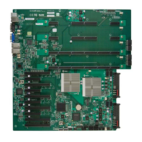
Checklist Congratulations on purchasing your computer system from an acknowledged leader in the industry. Supermicro systems are designed with the utmost attention to detail to provide you with the highest standards in quality and performance. For more information regarding this product, please visit our website at www. - Page 18 X8OBN-F Platform User’s Manual X8OBN-F Baseboard Image Note: All graphics shown in this manual were based upon the latest PCB Revision available at the time of publishing of the manual. The board you've received may or may not look exactly the same as the graphics...
- Page 19 Chapter 2: Overview X8OBN-F Baseboard Layout JWD1 JOH1 FP CRTL X8OBN-F Baseboard Fan6 Rev. 1.01 CPU Board Slot 4 Fan12 Fan5 Fan 11 CPU Board Slot 3 JP18 Fan4 CPU Board Slot 2 JP19 JP17 Fan 10 Fan 9 JPT1...
- Page 20 X8OBN-F Platform User’s Manual X8OBN-CPU Board Image X8OBN-CPU Board Layout X8OBN-CPU Rev.1.01 P2-DIMM6A P1-DIMM4A P2-DIMM5A P1-DIMM3A (for CPU2) (for CPU2) CPU2 (for CPU1) (for CPU1) P2-DIMM7A P1-DIMM1A P2-DIMM8A P1-DIMM2A P2-DIMM2A P1-DIMM8A P2-DIMM1A P1-DIMM7A (for CPU2) CPU1 (for CPU2) (for CPU1)
- Page 21 Chapter 2: Overview X8OBN-BR1 Bridge Card Image...
- Page 22 X8OBN-F Platform User’s Manual X8OBN-F Baseboard Layout JWD1 JOH1 FP CRTL X8OBN-F Baseboard Fan6 Rev. 1.01 CPU Board Slot 4 Fan12 Fan5 Fan 11 CPU Board Slot 3 JP18 Fan4 CPU Board Slot 2 JP19 JP17 Fan 10 Fan 9...
- Page 23 Chapter 2: Overview X8OBN-F Baseboard Quick Reference X8OBN-F Jumpers Jumper Description Default Setting JBT1 Clear CMOS See Chapter 3 JPB1 BMC Enabled Pins 1-2 (Enabled) JPG1 VGA Enabled Pins 1-2 (Enabled) JPME1 ME Mode Recovery Off (Normal) JPME2 ME Mode Select...
- Page 24 X8OBN-F Platform User’s Manual LAN1/LAN2 G-bit Ethernet Ports 1/2 (IPMI) LAN IPMI_Dedicated LAN PCI-E 2.0 x8 PCI-Express 2.0 x8 Slots (Slot3/Slot5/Slot7/Slot9)(See Note on P. 2-6) PCI-E 2.0 x8 in x16 PCI-Express 2.0 x8 in x16 Slots (Slot1/Slot2) (See Note on P.
- Page 25 Chapter 2: Overview Baseboard Features Baseboard Modular design with a baseboard with four CPU_board slots that support up to four CPU boards; The baseboard includes two 7500 IO hubs, one PLX PEX8648 PCI-E software controller and ten PCI-E slots; Each CPU board includes the following: •...
- Page 26 X8OBN-F Platform User’s Manual Super I/O • Winbond Super I/O 83527 Peripheral USB Devices Devices • Two (2) USB ports on the rear I/O panel (USB 0/1) • Two (2) USB connectors (4 ports) for front access (USB 2/3, USB 4/5) •...
- Page 27 (X8OBN-F Baseboard) Notes: 1. For IPMI Confi guration Instructions, please refer to the Embedded IPMI Confi guration User's Guide available @ http://www.supermicro.com/support/ manuals/. 2. For PCI-E expansion slots to work properly, please refer to the instruc- tions listed on Page 2-6.
- Page 28 X8OBN-F Platform User’s Manual System Block Diagram Note: This is a general block diagram and may not exactly represent the features on your baseboard. See the Baseboard Features pages for the actual specifi cations of each baseboard. 2-12...
-
Page 29: Chipset Overview
Chipset Overview Built upon the functionality and the capability of the Intel 7500 platform, the X8OBN-F baseboard provides the performance and support for eight-processor- based HPC/Cluster/Database servers. The 7500 platform consists of the 7500 Series Socket-LS (LGA 1567) processor, the 7500 (IOH), and the ICH10R (South Bridge). -
Page 30: Special Features
X8OBN-F Platform User’s Manual Special Features Recovery from AC Power Loss Basic I/O System (BIOS) provides a setting for you to determine how the system will respond when AC power is lost and then restored to the system. You can choose for the system to remain powered off (in which case you must press the power switch to turn it back on), or for it to automatically return to a power-on state. -
Page 31: Acpi Features
It is even more important for processors that have high CPU clock rates. The X8OBN-F baseboard includes two main system power connectors (JP21/22), four HDD power connectors (JP16~JP19), four GPU Power connectors (JPWR1~4), and a SATA DOM power connector (JWF1). Please connect these power connectors to the power supply to provide adequate power to the components and the system. -
Page 32: Super I/O
X8OBN-F Platform User’s Manual It is strongly recommended that you use a high quality power supply that meets the ATX power supply Specifi cation 2.02 or above. It must also be SSI compliant. (For more information, please refer to the website at http://www.ssiforum.org/). Addition- ally, in areas where noisy power transmission is present, you may choose to install a line fi... -
Page 33: Chapter 3 Installation
Chapter 3: Installation Chapter 3 Installation Static-Sensitive Devices Electrostatic Discharge (ESD) can damage electronic com ponents. To avoid dam- aging your system board, it is important to handle it very carefully. The following measures are generally suffi cient to protect your equipment from ESD. Precautions •... -
Page 34: Populating The Cpu Board
CPU socket plastic cap is in place, and none of the CPU socket pins are bent; otherwise, contact the retailer immediately. Refer to our website at www.supermicro.com for CPU/Memory support up- dates. Installing a CPU on the CPU Board Follow the instructions given in Chapter 1 to install the CPU board to the CPU board plate. -
Page 35: Installing The Cpu Heatsink On The Cpu Board
Chapter 3: Installation Installing the CPU Heatsink on the CPU Board If needed, apply the proper amount of thermal grease (with thickness of up to 0.13 mm) to the heatsink. (If you are using a heatsink purchased from SMC, please skip this step because the needed amount of the thermal grease has been applied to the heatsink.) Place the heatsink on top of the CPU so that the two mounting holes on the heatsink are aligned with those on the retention mechanism. -
Page 36: Installing Memory Modules On The Cpu Board
Notes: 1. Be sure to install the CPU board to the CPU board plate before installing any components to the CPU board. (See Chapter 1). 2. Check Supermicro's website for recommended memory modules. CAUTION Exercise extreme care when installing or removing DIMM modules to prevent any possible damage. -
Page 37: Installing The Baseboard Into The Chassis
Standoffs (20 pieces, if needed) Install the IO shield in the chassis. Locate the mounting holes on the baseboard and the matching mounting holes on the chassis. JWD1 JOH1 FP CRTL X8OBN-F Baseboard Fan6 Rev. 1.01 CPU Board Slot 4 Fan12 Fan5 Fan 11... -
Page 38: Installing The Populated Cpu Board On The Baseboard
X8OBN-F Platform User's Manual Installing the Populated CPU Board on the Baseboard JWD1 JOH1 FP CRTL X8OBN-F Baseboard Fan6 Rev. 1.01 CPU Board Slot 4 CPU Slot4 Fan12 Fan5 Fan 11 CPU Board Slot 3 CPU Slot3 JP18 Fan4 CPU Board Slot 2... -
Page 39: Installing The Bridge Card Between The Cpu Boards
Chapter 3: Installation Installing the Bridge Card between the CPU Boards Once you've installed populated CPU boards on the baseboard, you can install the X8OBN-BRI Bridge card between the CPU boards. (If only one CPU board is installed on the baseboard, please skip this step.) Note: A Bridge card is needed to connect the pair(s) of the CPU boards installed on Slot1 &... -
Page 40: Memory Support For The X8Obn-F Platform
X8OBN-F Platform User's Manual Memory Support for the X8OBN-F Platform Each X8OBN-F CPU Board supports up to 256 GB Registered ECC DDR3 1066 MHz memory in 16 DIMM slots. These RDIMMs run at 800/978/1066 via a memory buffer. X8OBN-CPU Rev.1.01... - Page 41 Chapter 3: Installation RDIMM Support POR on the 7500 Series Processor Platform DIMM Slots DIMMs RDIMM Type POR Speeds (in Ranks per DIMM per DDR Populated (RDIMM: Reg.= MHz) (Any Combination) Channel per DDR Registered) Channel Reg. ECC DDR3 800,978, 1066 SR, DR, or QR Note: Refer to the notes below for memory population instructions.
-
Page 42: Control Panel Connectors/I/O Ports
X8OBN-F Platform User's Manual Control Panel Connectors/I/O Ports The I/O ports are color coded in conformance with the PC 99 specifi cation. See the picture below for the colors and locations of the various I/O ports. Back Panel Connectors/I/O Ports... -
Page 43: Atx Ps/2 Keyboard And Ps/2 Mouse Ports
KB Clock Mouse Clock No Connection No Connection VCC: with 1.5A PTC (current limit) JWD1 JOH1 1. Keyboard FP CRTL X8OBN-F Baseboard Fan6 Rev. 1.01 2. Mouse CPU Board Slot 4 Fan12 Fan5 Fan 11 CPU Board Slot 3 JP18... -
Page 44: Universal Serial Bus (Usb)
X8OBN-F Platform User's Manual Universal Serial Bus (USB) FP USB (2/3, 4/5) Backplane USB (0/1) Pin Defi nitions Two Universal Serial Bus ports (USB Pin Defi nitions USB 2/4/8/10 USB 3/5 0/1) are located on the I/O back panel. Pin # Defi nition Pin # Defi... -
Page 45: Serial Ports
A Video (VGA) port is located next to COM1 on the I/O backplane. Refer to the board layout below for the location. 1. COM1 JWD1 JOH1 FP CRTL X8OBN-F Baseboard Fan6 2. COM2 Rev. 1.01 CPU Board Slot 4 3. VGA Fan12 Fan5... -
Page 46: Ethernet Ports
X8OBN-F Platform User's Manual Ethernet Ports LAN Ports Pin Defi nition Two Ethernet ports (LAN1/LAN2) are Pin# Defi nition located on the I/O backplane on the P2V5SB SGND baseboard. In addition, an IPMI_Dedi- TD0+ Act LED cated LAN is located above USB 0/1... -
Page 47: Unit Identifi Er Switch
Unit Identifi er Switch UID Switch A Unit Identifi er (UID) switch and two LED Pin# Defi nition Indicators are located on the X8OBN-F Ground baseboard. The UID switch is located next Ground to the LAN ports on the backplane. The Rear... -
Page 48: Front Control Panel
These connectors are designed specifi cally for use with Supermicro's server chassis. See the fi gure below for the descriptions of the various control panel buttons and LED indicators. Refer to the following section for descriptions and pin defi... -
Page 49: Front Control Panel Pin Defi Nitions
15 and 16 of JF1. Refer to the 3.3V table on the right for pin defi nitions. PWR LED A. NMI B. PWR LED JWD1 JOH1 FP CRTL X8OBN-F Baseboard Fan6 Rev. 1.01 CPU Board Slot 4 Ground Fan12 Fan5 Fan 11 CPU Board Slot 3 JP18 3.3 V... -
Page 50: Hdd Led
X8OBN-F Platform User's Manual HDD LED HDD LED Pin Defi nitions (JF1) The HDD LED connection is located Pin# Defi nition on pins 13 and 14 of JF1. Attach a 3.3V Standby cable here to indicate HDD activ- HD Active ity. -
Page 51: Overheat (Oh)/Fan Fail/Pwr Fail/Uid Led
PWR Supply Fail defi nitions. A. Front UID LED (Blue) B. OH/ Fail/PWR Fail LED (Red) C. PWR Supply Fail JWD1 JOH1 FP CRTL X8OBN-F Baseboard Fan6 Rev. 1.01 CPU Board Slot 4 Ground Fan12 Fan5 Fan 11 CPU Board Slot 3 JP18 3.3 V... -
Page 52: Reset Button
X8OBN-F Platform User's Manual Reset Button Reset Button Pin Defi nitions (JF1) The Reset Button connection is located Pin# Defi nition on pins 3 and 4 of JF1. Attach it to a Reset hardware reset switch on the computer Ground case. -
Page 53: Connecting Cables
Module) Devices is located at JWF1. Connect the appropriate cable here to provide power Ground support for your DOM devices. Ground JWD1 JOH1 FP CRTL X8OBN-F Baseboard Fan6 Rev. 1.01 P W R ( J P 2 2 ) CPU Board Slot 4 (Req'd) Fan12... -
Page 54: Fan Headers
X8OBN-F Platform User's Manual Fan Headers Fan Headers Fan Type # of Pins Q'ty Fan No. The X8OBN Baseboard has six system fan headers and four CPU_card fan IOH Fans 3-pin Fan7 (IOH1)/ Fan8 (IOH2) headers. All these are 4-pin fans and are... -
Page 55: Internal Buzzer
Pin Setting Defi nition close pins 6-7 with a cap. Pins 4-7 External Speaker Pins 6-7 Internal Speaker JWD1 JOH1 FP CRTL X8OBN-F Baseboard Fan6 Rev. 1.01 CPU Board Slot 4 Fan12 Fan5 Fan 11 CPU Board Slot 3 JP18 Fan4... -
Page 56: Tpm Header/Port 80
X8OBN-F Platform User's Manual TPM Header/Port 80 TPM/Port 80 Header Pin Defi nitions A Trusted Platform Module/Port 80 Pin # Defi nition Pin # Defi nition header is located at JTPM1 to provide LCLK TPM and Port 80 support, which will LFRAME# <(KEY)>... -
Page 57: T-Sgpio 1/2 Headers
Ground onboard SATA connections. See the Clock table on the right for pin defi nitions. Note: NC= No Connection JWD1 JOH1 FP CRTL X8OBN-F Baseboard Fan6 Rev. 1.01 CPU Board Slot 4 Fan12 Fan5 Fan 11 CPU Board Slot 3... -
Page 58: Jumper Settings
X8OBN-F Platform User's Manual Jumper Settings Explanation of Jumpers Connector Pins To modify the operation of the baseboard, jumpers can be used to choose between optional settings. Jumpers create shorts be- Jumper tween two pins to change the function of the connector. -
Page 59: Cmos Clear
See the table on the right for jumper settings. Watch Dog must also be enabled in the BIOS. A. Clear CMOS JWD1 JOH1 FP CRTL X8OBN-F Baseboard B. Watch Dog Enable Fan6 Rev. 1.01 CPU Board Slot 4 Fan12 Fan5... -
Page 60: Vga Enable
X8OBN-F Platform User's Manual VGA Enable VGA Enable Jumper Settings Jumper JPG1 allows the user to enable Jumper Setting Defi nition the onboard VGA connector. The default Enabled (Default) setting is 1-2 to enable the connection. Disabled See the table on the right for jumper settings. -
Page 61: Bmc Enable
In single operation mode, online upgrade will be available via Re- covery mode. See the table on the right for jumper settings. JWD1 JOH1 FP CRTL X8OBN-F Baseboard Fan6 Rev. 1.01 CPU Board Slot 4 Fan12 Fan5 Fan 11... -
Page 62: Manufacturer Mode Select
X8OBN-F Platform User's Manual Manufacturer Mode Select ME Mode Select Jumper Settings Close this jumper (JPME2) to bypass SPI fl ash Jumper Setting Defi nition security and force the system to use the Manu- Open Normal (Default) facturer Mode which will allow you to fl ash the... -
Page 63: Bmc Reset
Closed BMC Reset table on the right for jumper settings. Closed Normal (Default) A. BMC Reset En- JWD1 JOH1 FP CRTL X8OBN-F Baseboard Fan6 Rev. 1.01 able CPU Board Slot 4 Fan12 Fan5 Fan 11 CPU Board Slot 3 JP18... -
Page 64: X8Obn-F Platform User's Manual
X8OBN-F Platform User's Manual 3-10 Onboard LED Indicators Activity LED Link LED GLAN LEDs Rear View (when facing the Two LAN ports (LAN 1/LAN 2) are located rear side of the chassis) on the I/O Backplane of the baseboard. LAN 1/LAN 2 Link LED (Right) LED State Each Ethernet LAN port has two LEDs. -
Page 65: Rear Uid Led
Blinking table at right for more information. Note: LED Indicators that are not documented in the manual are for test- ing only. JWD1 JOH1 FP CRTL X8OBN-F Baseboard Fan6 Rev. 1.01 CPU Board Slot 4 Fan12 Fan5 Fan 11 CPU Board Slot 3... -
Page 66: 3-11 Serial Ata Connections
Pin# Defi nition There are six Serial ATA Ports (I- Ground SATA0 ~I-SATA5) located on the TX_P X8OBN-F. These ports, supported by TX_N the Intel ICH10R South Bridge, pro- Ground vide serial-link signal connections, RX_N which are faster than the connections RX_P of Parallel ATA. -
Page 67: Chapter 4 Troubleshooting
Chapter 4: Troubleshooting Chapter 4 Troubleshooting Troubleshooting Procedures Use the following procedures to troubleshoot your system. If you have followed all of the procedures below and still need assistance, refer to the ‘Technical Support Procedures’ and/or ‘Returning Merchandise for Service’ section(s) in this chapter. Note: Always disconnect the power cord before adding, changing or installing any hardware components. -
Page 68: No Video
X8OBN-F Platform User's Manual No Video If the power is on but you have no video, remove all the add-on cards and cables. Use the speaker to determine if any beep codes exist. Refer to the Appendix for details on beep codes. -
Page 69: Memory Errors
Memory support: Make sure that the memory modules are supported by test- ing the modules using memtest86 or a similar utility. Note: Refer to the product page on our Website at http:\\www.supermicro. com for memory compatibility list. HDD support: Check if all hard disk drives (HDDs) work properly. Replace the bad HDDs with good ones. -
Page 70: Technical Support Procedures
Technical Support Procedures Before contacting Technical Support, please take the following steps. Also, please note that as a baseboard manufacturer, Supermicro also sells motherboards through its channels, so it is best to fi rst check with your distributor or reseller for trouble-... -
Page 71: Frequently Asked Questions
It is recommended that you do not upgrade your BIOS if you are not experiencing any problems with your system. Updated BIOS fi les are located on our website at http://www.supermicro.com. Please check our BIOS warning message and the information on how to update your BIOS on our website. Select your baseboard model and download the BIOS fi... -
Page 72: Returning Merchandise For Service
Note : The SPI BIOS chip used on this baseboard cannot be removed. Send your baseboard back to our RMA Department at Supermicro for repair. For BIOS Recovery instructions, please refer to the AMI BIOS Recovery Instructions posted at http://www.supermicro.com. -
Page 73: Chapter 5 Bios
BIOS Introduction This chapter describes the AMI BIOS Setup Utility for the X8OBN-F Baseboard. The AMI ROM BIOS is stored in a Flash EEPROM and can be easily updated. This chapter describes the basic navigation of the AMI BIOS Setup Utility screens. -
Page 74: Starting The Setup Utility
Warning! Do not upgrade the BIOS unless your system has a BIOS-related issue. Flashing the wrong BIOS can cause irreparable damage to the system. In no event shall Supermicro be liable for direct, indirect, special, incidental, or consequential damages arising from a BIOS update. If you have to update the BIOS, do not shut down or reset the system while the BIOS is updating. - Page 75 Chapter 4: AMI BIOS • Build Date: This item displays the date when this BIOS was completed. Memory Information: The following memory information will be displayed: • Total Memory: This item displays the size of memory available in the system. System Language The feature allows the user to select a language setting for the Setup utility.
-
Page 76: Advanced Setup Confi Guration
X8OBN-F Platform User's Manual Advanced Setup Confi guration Use the arrow keys to select the Advanced Setup menu and press <Enter> to ac- cess the submenu items. PCI Subsystem Settings PCI Bus Driver Version: This feature displays the version number of the PCI Bus Driver used in this system. - Page 77 Chapter 4: AMI BIOS VGA Palette Snoop If this feature is set to Enabled, a PCI card that does not have its own VGA color palette built-in will detect a video_card palette to mimic it for color scheme support. The options are Enabled and Disabled. PERR# Generation Select Enabled to allow a PCI device to generate a PERR number for a PCI Bus Signal Error Event.
-
Page 78: Trusted Computing
X8OBN-F Platform User's Manual PCI Express Link Settings ASPM Support This feature allows the user to set the Active State Power Management (ASPM) level for a PCI-E device. Select Force L0 to force all PCI-E links to operate at L0 state. - Page 79 Chapter 4: AMI BIOS TPM Support Select Enabled to enable TPM (Trusted Platform Module) support for system security and data integrity. The options are Disabled and Enabled. If this option is set to Enabled, the following items will display. TPM State Select Enabled to display the status of TPM support for this system.
- Page 80 X8OBN-F Platform User's Manual WHEA Support Select Enabled to enable WHEA support which will provide a common infrastruc- ture for the system to handle hardware errors on the Windows OS platforms in order to reduce system crashes due to hardware errors and to enhance system recovery and health monitoring.
- Page 81 Chapter 4: AMI BIOS • 64-bit : This item indicates if 64-bit is supported by the CPU. CPU Spread Spectrum Select Enable to enable CPU Clock Spectrum support, which will allow the BIOS to monitor and attempt to reduce the level of Electromagnetic Interference caused by the components whenever needed.
- Page 82 X8OBN-F Platform User's Manual ing multiple "virtual" systems in one physical computer. The options are Enabled and Disabled. Note: Please reboot the system for any change in this setting to take effect. Please refer to Intel’s website for detailed information.
-
Page 83: Runtime Error Logging
Chapter 4: AMI BIOS Package C-State Limit (Available when the C-State Tech is enabled) If this package is set to Auto, the AMI BIOS will automatically set a limit on the reg- ister of the C-State package. The options are No Limit, C0, C1, C3, C6, and C7. Local APIC (Available when supported by the CPU and the OS) The local Advanced Programmable Interrupt controller (Local APIC), embedded in a CPU, manages all external interrupts for the CPU in a 4-way or 8-way system. - Page 84 X8OBN-F Platform User's Manual Memory Correctable Error Threshold This feature allows the user to enter the threshold value for memory correctable errors. The default setting is 10. Legacy OpROM (Option ROM) Confi guration Legacy OpROM Support Use this feature to confi gure Option ROM settings which will allow the system to boot up via a legacy network device.
- Page 85 Chapter 4: AMI BIOS ICH RAID Code Base (Available when the option-RAID is selected) Select Intel to use Intel SATA RAID fi rmware for Intel SATA RAID confi guration. Select Adaptec to use Adaptec fi rmware for Adaptec SATA RAID confi guration. The options are Intel and Adaptec.
- Page 86 X8OBN-F Platform User's Manual Device Power-up Delay Select Auto to use the default maximum time value for a USB device to wait before it reports itself to the Host Controller. The default maximum wait time for a root port is 100 ms.
- Page 87 Chapter 4: AMI BIOS Fan Speed Readings The following fan speeds are displayed: Fan1 Speed~Fan 12 Speeds Baseboard Voltage and Temperature The he following temperature and voltage settings will be displayed (in degrees in Celsius and Fahrenheit) as detected by the BIOS: •...
-
Page 88: Serial Port Console Redirection
X8OBN-F Platform User's Manual Watchdog Function If enabled, the WatchDog Timer will cause the system to reboot when the system is inactive for more than 5 minutes. The options are Enabled and Disabled. Super IO Confi guration (for the WPCM450 chip) Super IO Confi... -
Page 89: Console Redirection Settings
Chapter 4: AMI BIOS Console Redirection Settings This feature allows the user to specify how the host computer will exchange data with the client computer, which is the remote computer used by the user. Terminal Type This feature allows the user to select the target terminal emulation type for Console Redirection. - Page 90 X8OBN-F Platform User's Manual Resolution 100x31 Select Enabled for extended-terminal resolution support. The options are Dis- abled and Enabled. Legacy OS Redirection Use this feature to select the number of rows and columns used in Console Redirection for legacy OS support. The options are 80x24 and 80x25.
-
Page 91: Chipset
Chapter 4: AMI BIOS acter Set. Select VT-UTF8 to use UTF8 encoding to map Unicode characters into one or more bytes. The options are ANSI, VT100, VT100+, and VT-UTF8. Network Stack Network Stack Select Enabled enable PXE (Preboot Execution Environment) or UEFI (Unifi ed Extensible Firmware Interface) for network stack support. - Page 92 X8OBN-F Platform User's Manual ® Intel VT-d Select Enabled to enable Intel Virtualization Technology support for Direct I/O VT-d by reporting the I/O device assignments to VMM through the DMAR ACPI Tables. This feature offers fully-protected I/O resource-sharing across the Intel platforms, providing the user with greater reliability, security and availability in networking and data-sharing.
- Page 93 Chapter 4: AMI BIOS • IOH1/IOU0 • IOH1/IOU1 • IOH2/IOU2 • IOH2/IOU0 • IOH2/IOU1 IOH Thermal Sensors This feature allows the user to confi gure integrated thermal sensor settings embed- ded in the 7500 chipset. Thermal Sensors Select Enabled to enable integrated thermal sensors embedded in the 7500 chipset.
- Page 94 X8OBN-F Platform User's Manual QPI Link Frequency Select This feature allows the user to set the QPI Link Frequency. Select Auto for the AMI BIOS to automatically set the QPI Link Frequency for optimal system per- formance. The options are Auto, 4.8 GT/s, 5.866 GT/s, and 6.4 GT/s.
- Page 95 Chapter 4: AMI BIOS • Current Memory Speed: This item displays the current memory speed of the system. • Mirroring: This item indicates if memory mirroring is supported by the system for data security enhancement. • Sparing: This item indicates if memory sparing is supported by the system for memory performance enhancement.
- Page 96 X8OBN-F Platform User's Manual detected in the system. The options are Auto, Force DDR3 800, Force DDR3 978 and Force DDR3 1067. High Temperature Select Enabled for high temperature support for onboard memory modules. The options are Enabled and Disabled.
-
Page 97: South Bridge
Chapter 4: AMI BIOS South Bridge This submenu allows the user to confi gure the following South Bridge settings. South Bridge Chipset Confi guration This feature allows the user to confi gure the following South Bridge parameters. SMBus Controller Select Enabled to enable the SMBus (System Management Bus) controller to im- prove system management. - Page 98 X8OBN-F Platform User's Manual struction embedded in the CPU. The High Precision Event Timer is used to replace the 8254 Programmable Interval Timer. The options are Enabled and Disabled. PCI-Express_Port Confi guration This feature allows the user to confi gure the following PCI-E_port settings: PCI-Express Port 1~ PCI-Express Port 5 Select Enabled to enable the PCI-E port specifi...
-
Page 99: Server Management
Chapter 4: AMI BIOS Server Management This section allows the user to confi gure Server Management settings. BMC Support Select Enabled to enable the Baseboard Management Controller. The options are Enabled and Disabled. System Event Log Enabling/Disabling Options Use this feature to enable or disable the following System Event Log (SEL) set- tings. - Page 100 X8OBN-F Platform User's Manual When SEL is Full This feature allows the user to decide what the system shall do when the System Event Log is full. This feature is not available when the FRB-2 Timer is disabled. The options are Do Nothing, Power Down and Reset.
-
Page 101: Iscsi
Chapter 4: AMI BIOS iSCSI This section allows the user to confi gure iSCSI settings. iSCSI Initiator Name Use this feature to specify the name of your iSCSI initiator. This name will be unique worldwide. Be sure to use the iSCSI Qualifi ed Name (iqn) format when naming your iSCSI Initiator. - Page 102 X8OBN-F Platform User's Manual Quiet Boot This feature allows the user to select the bootup screen display between the POST messages and the OEM logo. Select Disabled to display the POST messages. Select Enabled to display the OEM logo instead of the normal POST messages.
-
Page 103: Security
Chapter 4: AMI BIOS Boot Option Priorities Boot Option#1/Boot Option#2 Use this item to set the system boot sequence. If Built-in EFI (Extensible Firmware Interface) Shell is selected, the Built-in EFI Shell will become the fi rst component to boot. The default setting for Boot Option #1 is Built-in EFI Shell, and for Option#2 is Windows Boot Manager. -
Page 104: Save & Exit
X8OBN-F Platform User's Manual Save & Exit Use this section to confi gure Save & Exit settings. Save Changes and Exit When you have completed the system confi guration changes, select this feature and press <Yes> in the dialog box to save the changes you've made and reboot the system. - Page 105 Chapter 4: AMI BIOS Discard Changes Select Discard Changes and press <Yes> in the dialog box to discard any changes you've made and return to the Setup Utility. Restore Defaults Select this feature and press <Yes> in the dialog box for the AMI BIOS to automati- cally load Optimal Defaults to the BIOS Settings.
- Page 106 X8OBN-F Platform User's Manual Note 5-34...
-
Page 107: Appendix A Bios Error Beep Codes
Appendix A: BIOS POST Error Codes Appendix A BIOS Error Beep Codes During the POST (Power-On Self-Test) routines, which are performed each time the system is powered on, errors may occur. Non-fatal errors are those which, in most cases, allow the system to continue the bootup process. - Page 108 X8OBN-F Platform User's Manual Notes...
-
Page 109: Appendix B Software Installation Instructions
To install these programs, click the icons to the right of these items. Note: To install the Windows OS, please refer to the instructions posted on our Website at http://www.supermicro.com/support/manuals/. Driver/Tool Installation Display Screen Note 1. Click the icons showing a hand writing on the paper to view the readme fi... -
Page 110: B-2 Confi Guring Superdoctor Iii
X8OBN-F Platform User's Manual B-2 Confi guring SuperDoctor III The SuperDoctor III program is a Web-based management tool that supports remote management capability. It includes Remote and Local Management tools. The local management is called the SD III Client. The SuperDoctor III program included on the CDROM that came with your baseboard allows you to monitor the environment and operations of your system. - Page 111 Appendix B: Software Installation Instructions SuperDoctor III Interface Display Screen-II (Remote Control) Note: SD III Software and the user's guide can be downloaded from our Website at: http://www.supermicro.com/products/accessories/software/ SuperDoctorIII.cfm. For Linux, we will still recommend that you use SuperDoctor II.
- Page 112 X8OBN-F Platform User's Manual Notes...
- Page 113 (Disclaimer Continued) The products sold by Supermicro are not intended for and will not be used in life support systems, medical equipment, nuclear facilities or systems, aircraft, aircraft devices, aircraft/emergency communication devices or other critical systems whose failure to perform be reasonably expected to result in signifi cant injury or loss of life or catastrophic property damage.
Need help?
Do you have a question about the X8OBN-F and is the answer not in the manual?
Questions and answers