Table of Contents
Advertisement
SERVICE MANUAL
COMPACT COMPONENT SYSTEM
FS-SD78V / FS-SD98V
REMOTE CONTROL
DIMMER
SLEEP
FM MODE
DISPLAY
MPX
DOOR SLIDE
TONE
CLOCK
AHB PRO
CONTROL
/ TIMER
PLAY MODE
REPEAT
CANCEL
HIGHLIGHT
VIDEO INTRO
STILL
PBC ON / OFF
ON SCREEN
VCD NUMBER
UP
PREV
SELECT
NEXT
SET
DOWN
FADE MUTING
VCD NUMBER
CD
FM / AM
MD / AUX
VOLUME
REMOTE CONTROL
DIMMER
SLEEP
FM MODE
DISPLAY
MPX
DOOR SLIDE
TONE
CLOCK
AHB PRO
CONTROL
/ TIMER
PLAY MODE
REPEAT
CANCEL
HIGHLIGHT
VIDEO INTRO
STILL
PBC ON / OFF
VCD NUMBER
ON SCREEN
UP
PREV
SELECT
NEXT
SET
DOWN
FADE MUTING
VCD NUMBER
CD
MD / AUX
FM / AM
VOLUME
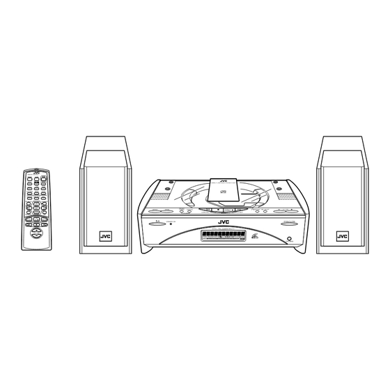
SP-SD78V, SD98V
FS-SD78V and FS-SD98V are different only speaker cabinet.
Contents
These models not have adjustment.
Safety Precautions
FS-SD58V
N T S C / PA L C O M PAT I B I L I T Y
SP-SD58V
CA-SD58V
N T S C / PA L C O M PAT I B I L I T Y
CA-SD78V, CA-SD98V
These models are different only speaker systems.
1-2
1-3
1-4
1-5
1-6
14
1-15
1-15
This service manual is printed on 100% recycled paper.
COPYRIGHT
2000 VICTOR COMPANY OF JAPAN, LTD.
FS-SD58V / FS-SD78V / FS-SD98V
SP-SD58V
SP-SD78V, SD98V
unit TOC read
treatment device wire
Area Suffix
FS-SD58V
Hong Kong
UB
China
UF
Singapore
US
FS-SD78V / FS-SD98V
China
UF
Singapore
US
1-16
1-17
1-18
No.20882
Nov. 2000
Advertisement
Chapters
Table of Contents


Need help?
Do you have a question about the FS-SD58V and is the answer not in the manual?
Questions and answers