
Related Manuals for Nexsan sasbeast


Summary of Contents for Nexsan sasbeast
- Page 1 Installation and Maintenance Manual Version 2.6 NEXSAN 1445 Lawrence Drive, Thousand Oaks, CA 91320 | p. 866.4.NEXSAN | www.nexsan.com...
- Page 2 COPYRIGHT Copyright © 2009–2012 Nexsan Corporation. All Rights Reserved. TRADEMARKS ® ® ™ Nexsan , SATABeast , SASBeast , and the Nexsan logo are trademarks or registered trademarks of Nexsan Corporation. All other trademarks and registered trademarks are the property of their...
-
Page 3: About This Document
REVISION NOTICE Nexsan reserves the right to make changes to this manual, as well as the equipment and software described in this manual, at any time without notice. This manual may contain links to web sites that were current at the time of publication, but have since been moved or become inactive. -
Page 4: Contact Information
NEXSAN Worldwide Headquarters — Los Angeles, USA 1445 Lawrence Drive Thousand Oaks, CA 91320 Telephone: 866-4-NEXSAN (866-463-9726), or 805-418-2700 outside of North America Technical Services: 866-2-NEXSAN (866-263-9726), or 760-690-1111 outside of North America Fax: 805-418-2799 E-mail: sales@Nexsan.com, support@Nexsan.com NEXSAN San Diego, USA... -
Page 5: Table Of Contents
Conventions....................... vii Text ........................vii Notes, Cautions, and Warnings ................vii Safety Information ..................... vii Revision History......................viii Chapter 1: Overview of the SATABeast/SASBeast......... 1 Front Panel ......................... 1 LEDs ........................2 Switches........................ 2 Rear Panel........................3 Field-Replaceable Modules................... 3 Other Modules....................... - Page 6 Contents Chapter 3: Installing the SATABeast/SASBeast ........13 Preparing the Mounting Rails ................... 13 Mount the SATABeast/SASBeast................15 Restore the Rear Modules..................17 PSUs ........................17 RAID Controllers ....................17 Load the Disk Drives ....................18 Attach Communication Cables ................. 20 Power Up the SATABeast/SASBeast...............
-
Page 7: About This Manual
(Fibre Channel host), SATABeast Xi, SASBeast, etc. The term “SATABeast/SASBeast” is used throughout for all versions. This document describes the parts, functions, and installation procedures for the SATABeast/SASBeast. It covers the SATABeast/SASBeast only. For information about other Nexsan units, see the Installation and Maintenance Manuals that come with each product. Conventions Text •... -
Page 8: Revision History
Version 2.3, March 2010: New format applied throughout; new note regarding multiple SATABeast/ SASBeast units added under Before you begin on page 5, under Disk Drives on page 15, and under Tiered Storage & SAS Drive installation guide on page 29. -
Page 9: Chapter 1: Overview Of The Satabeast/Sasbeast
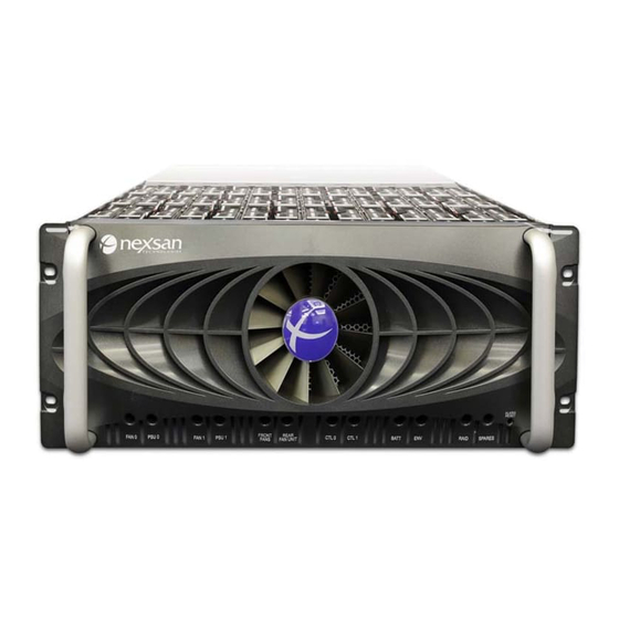
7. Environment 10. Alarm reset 3. Front fans 8. RAIDs 4. Auxiliary blower unit 9. Spare disk drives Figure 1.1: SATABeast/SASBeast front panel 8 9 10 Figure 1.2: SATABeast Xi front panel SATABeast/SASBeast Installation and Maintenance Manual v2.6, January 2012 www.nexsan.com... -
Page 10: Leds
The alarm will sound again if any additional errors occur. The Problems page (under System Information) in the graphical user interface (GUI) displays information about the event which triggered the alarm (see the Nexsan User Manual). SATABeast/SASBeast Installation and Maintenance Manual v2.6, January 2012... -
Page 11: Rear Panel
8. Expansion 13. Fibre Channel status 14. Expansion status Figure 1.3: SATABeast/SASBeast rear panel Field-Replaceable Modules 1. Power Supply Units (PSUs) (2). Each unit can be field-replaced in the event of a PSU or PSU fan failure (see Power Supply Units (PSUs) on page 21). -
Page 12: Leds
Chapter 1 — Overview of the SATABeast/SASBeast 8. Two expansion ports (OUT P0 and OUT P1) per RAID Controller: Mini-SAS 26 pin I-Pass (8088) expansion connectors, each with four 3GB/s SAS links, used to connect Nexsan expansion units to the SATABeast/SASBeast. -
Page 13: Drive Bay Interior
Drive Bay Interior 1. Disk drives 2. Disk status LEDs Figure 1.4: SATABeast/SASBeast drive bay interior Field Replaceable Modules 1. Disk Drives: Up to 42 3.5" disk drives. Disk drives can be field-replaced in the event of failure (see Disk Drives on page 25). -
Page 14: Dimensions
Two 1100 W load-sharing, hot-pluggable, redundant PSUs. Cooling • Front panel: Three (3) 120cfm 12V axial fans (life 40,000 hrs). (SASBeast has uprated fans) • PSUs: Two (2) 60cfm 12V axial fans per PSU (life 40,000 hrs), for a total of four. -
Page 15: Chapter 2: Getting Started
Chapter 2 Getting Started This manual is designed to enable the user to install and configure the SATABeast/SASBeast quickly and safely. Please read this document carefully and review all of the information in this section before installing the SATABeast/SASBeast. Taking Delivery of the SATABeast/SASBeast Upon receipt of your SATABeast/SASBeast, inspect the packaging for damage that may have been sustained in transit. - Page 16 (16) screws for securing the assemblies to the rack twenty (20) screws for securing the side rails to the chassis four (4) rack bolts and four (4) cage nuts for securing the SATABeast/SASBeast to the rack • two (2) power cables •...
-
Page 17: Before Installation
7. Remove the outer packging sleeve. Figure 2.5: Removing the outer packaging sleeve 8. With the help of a second person, carefully lift the SATABeast/SASBeast unit out of the packaging. Figure 2.6: Removing the unit from the box CAUTION: When removing the SATABeast/SASBeast from the packaging, DO NOT lift the unit by any plastic parts or module handles on the chassis. -
Page 18: Prepare The Site
• Situate the rack so that full air flow at both the front and the rear of the SATABeast/SASBeast is possible. •... -
Page 19: V2.6, January
It may be helpful to label them “Top” and “Bottom” before removing them. Set the PSUs and RAID Controller(s) aside. 2. Attach the inner side rails to the sides of the SATABeast/SASBeast unit: a. Separate the inner and outer side rails. - Page 20 Figure 2.10: Attaching the inner side rails to the chassis, left side NOTE: If you are installing more than one SATABeast/SASBeast unit, keep each unit’s disk drives with the unit they shipped with so as to avoid installing them into the wrong unit.
-
Page 21: Chapter 3: Installing The Satabeast/Sasbeast
Chapter 3 Installing the SATABeast/SASBeast The SATABeast/SASBeast comes in single-controller and dual-controller configurations. These instructions assume a dual-controller unit installation, but where the steps differ, additional instructions for single-controller units are provided. Preparing the Mounting Rails 1. Attach the outer side rails to the front mounting brackets. - Page 22 5. Insert the cage nuts above and below each rail. Figure 3.4: Inserting the cage nuts The mounting rails are now ready to receive the SATABeast/SASBeast unit. SATABeast/SASBeast Installation and Maintenance Manual v2.6, January 2012...
-
Page 23: Mount The Satabeast/Sasbeast
3. With the help of a second person, lift the SATABeast/SASBeast unit, carefully line up the inner rails with the rack rails, and slide the chassis into the rack, leaving a few inches between the front of the unit and the front of the rack. - Page 24 Chapter 3 — Installing the SATABeast/SASBeast 4. While still supporting the unit from below, tighten the mounting rail screws at the front of each rail. Figure 3.7: Tightening the front rack mount screws 5. Slide the unit the rest of the way into the rack so that the mounting ears sit against the rack.
-
Page 25: Restore The Rear Modules
1. Make sure that the RAID Controller is right side up. There is a notice in red on the top of the controller to guide you. 2. Insert the RAID Controller into the slot and carefully slide it back until it stops moving. Figure 3.11: Sliding the RAID Controller into place SATABeast/SASBeast Installation and Maintenance Manual v2.6, January 2012 www.nexsan.com... -
Page 26: Load The Disk Drives
Chapter 3 — Installing the SATABeast/SASBeast 3. Swivel the latching tabs inward to seat the RAID Controller. Figure 3.12: Seating the RAID Controller with the latch tabs 4. Tighten the retaining bolts to lock the RAID Controller in place. Figure 3.13: Locking the RAID Controller in place 5. - Page 27 5. Replace the top cover, close the front face, and replace the front panel retaining screws. 6. Slide the unit back into the rack. SATABeast/SASBeast Installation and Maintenance Manual v2.6, January 2012 www.nexsan.com...
-
Page 28: Attach Communication Cables
Chapter 3 — Installing the SATABeast/SASBeast 7. Using the supplied bolts, bolt the face of the SATABeast/SASBeast unit to the rack. Figure 3.18: Bolting the SATABeast/SASBeast to the rack Attach Communication Cables Connect all necessary communication cables to the RAID Controller (or Controllers) on the rear of the unit (see Rear Panel on page 3): •... -
Page 29: Chapter 4: Field Replacement Of Modules
Chapter 4 Field Replacement of Modules The SATABeast/SASBeast is designed so that some of its components can be replaced without turning off the unit or interrupting its functioning. The field-replaceable modules are: • the two PSUs • the one or two RAID Controllers •... - Page 30 SATABeast/SASBeast unit. 8. In the graphical user interface (GUI), go to the Home page and verify that the status bar for the new Power Supply Unit is green. See the Nexsan User Manual for more information. SATABeast/SASBeast Installation and Maintenance Manual v2.6, January 2012...
-
Page 31: Raid Controllers
CTL 1 LED indicates that the bottom controller has failed. The Home page of the graphical user interface (GUI) also tells you which unit has failed (see the Nexsan User Manual). NOTE: In some cases, a RAID Controller needs to be replaced even if it has not failed outright. In this case, you must determine which RAID Controller to replace by following the troubleshooting procedures in the Nexsan User Manual. - Page 32 5. Make sure that the replacement RAID Controller is right side up. There is a notice in red on the top of the controller to guide you. NOTE: If you have a Nexsan expansion unit attached to your SATABeast/SASBeast storage unit, plug the expansion cables from the expansion unit into the expansion ports on the replacement RAID Controller BEFORE you insert the RAID Controller into its slot.
-
Page 33: Disk Drives
Doing so may damage the unit or overbalance the rack. 1. Unbolt the face of the SATABeast/SASBeast unit from the rack. Figure 4.8: Unbolting the SATABeast/SASBeast from the rack 2. Pull the unit forward until there is enough room to remove the top cover. - Page 34 5). A red LED indicates the failed drive. The Disk Drives page (under RAID Information) of the graphical user interface (GUI) also tells you which drive has failed (see the Nexsan User Manual). 6. Disengage the disk by slipping the hooks on the supplied disk-extraction handle underneath the studs on the side of the disk and swiveling the handle upright.
- Page 35 See the Nexsan User Manual for more information. NOTE: If the status bar for the new drive is gray, you must manually assign the drive. See the Nexsan User Manual for instructions.
- Page 36 Chapter 4 — Field Replacement of Modules SATABeast/SASBeast Installation and Maintenance Manual v2.6, January 2012 www.nexsan.com...
-
Page 37: Common Terms And Abbreviations
Also called an ESD strap or a grounding bracelet. Auxiliary Blower Unit A module of the SATABeast/SASBeast that provides cooling for the unit’s RAID Controllers and disk drives. The smallest unit of digital data, representing a 0 or a 1. Abbreviated “b”. - Page 38 Fibre Channel port Any entity that actively communicates over a Fibre Channel network. Usually implemented in a device such as disk storage or a Fibre Channel switch. In Nexsan storage units, the Fibre Channel ports support 2Gb/s, 4Gb/s, or 8Gb/s connections.
- Page 39 TCP/IP network. See local area network. Light Emitting Diode. LEDs are used for indicator lights on the front and back of Nexsan storage units. local area network A computer network that links devices within a small geographic area, such as a building or group of adjacent buildings.
- Page 40 If an array disk fails, the RAID Controller rebuilds the data from the failed disk onto the spare disk, which then becomes part of the array. In Nexsan storage systems, there are two kinds of spare disk: “pool spares”, which can be used by any RAID array in the unit; and “dedicated spares”, which are assigned to a specific array.
- Page 42 760-690-1111 outside of North America Technical Services: +44 (0)1332 291600 Europe, Fax: 805-418-2799 760-690-1111 USA E-mail: sales@Nexsan.com, support@Nexsan.com E-mail: sales@Nexsan.com, support@Nexsan.com NEXSAN San Diego, USA Copyright © 2009–2012 Nexsan Corporation. All Rights Reserved. 302 Enterprise Street ® ® ™ Nexsan , SATABeast , SASBeast...
Need help?
Do you have a question about the sasbeast and is the answer not in the manual?
Questions and answers