Advertisement
Effective : October, 2002
SERVICE MANUAL
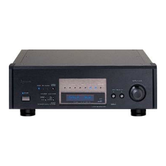
D D - - 7 7 0 0
CONTENTS
PC boards shown are viewed from parts side.
●
Parts marked with * require longer delivery time.
●
The parts with no reference number or no parts number in the
●
exploded views are not supplied.
As regards the resistors and capacitors, refer to the circuit diagrams
●
contained in this manual.
Parts marked with this sign are safety critical components. They
£
●
must be replaced with identical components - refer to the appropriate
parts list and ensure exact replacement.
Parts of [ ] mark can be used only with the version designated.
●
[US]:U.S.A. [C]:CANADA [E]:EUROPE
Multi D/A Converter
・ ・ ・ ・ ・ ・ ・ ・ ・ ・ ・ ・ ・ ・ ・ ・ ・ ・ ・ ・ ・ ・ ・ ・ ・ ・ ・ ・ ・ ・ ・ ・ ・ ・ ・ ・ ・ ・
・ ・ ・ ・ ・ ・ ・ ・ ・ ・ ・ ・ ・ ・ ・ ・ ・ ・ ・ ・ ・ ・ ・ ・
・ ・ ・ ・ ・ ・ ・ ・ ・ ・ ・ ・ ・ ・ ・ ・ ・
・ ・ ・ ・ ・ ・ ・ ・ ・ ・ ・ ・ ・ ・ ・ ・ ・ ・ ・ ・ ・ ・ ・ ・
・ ・ ・ ・ ・ ・ ・ ・ ・ ・ ・ ・ ・ ・ ・ ・ ・ ・ ・ ・ ・ ・ ・ ・ ・ ・ ・
NOTES
2
3
5
9
17
S-0077A
Advertisement

Related Manuals for Teac D-70


Summary of Contents for Teac D-70
-
Page 1: Table Of Contents
SERVICE MANUAL D D - - 7 7 0 0 Multi D/A Converter CONTENTS 1 SPECIFICATIONS ・ ・ ・ ・ ・ ・ ・ ・ ・ ・ ・ ・ ・ ・ ・ ・ ・ ・ ・ ・ ・ ・ ・ ・ ・ ・ ・ ・ ・ ・ ・ ・ ・ ・ ・ ・ ・ ・ 2 ADJUSTMENTS AND CHECKS ・... -
Page 2: Specifications
1 SPECIFICATIONS Electrical characteristics (at 24bit/44.1kHz input) General Frequency response ........20Hz-20kHz ±0.3dB Power supply ........AC 230V, 50Hz (Europe model) S/N ratio ................116dB AC 120V, 60Hz (U.S.A./Canada model) Dynamic range..............108dB AC 220V, 60Hz (Korea model) THD ..................0.0025% Power consumption ..............26W Channel separation ..............115dB Dimensions (WxHxD) ........465 x 162 x 369 (mm) Weight................about 25 kg Valid sampling frequencies (kHz) -
Page 3: Adjustments And Checks
2 ADJUSTMENTS AND CHECKS 2-1 Test Mode 2-2 Audio System 2-1-1 Getting into Test Mode Setting While holding down the INPUT SELECTOR buttons, CLOCK MODE: PLL < > power on the unit and hit the DIGITAL FILTER button repeatedly. AES3 INPUT: SINGLE DIGITAL FILTER: FIR DIGITAL IN: Fs=44.1kHz, FullBit 2-1-2 Version Display... - Page 4 2-2-2 Output level check 1. Connect the AC voltmeter to the LINE OUT. 2. Play the track 2 (1kHz, 0dB) of the MCD-111, and check the output level. Specifications: 2.2 0.2Vrms (100kΩ load, RCA) ± 0.2Vrms (100kΩ load, XLR) ± 2-2-3 Distortion check 1.
-
Page 5: Exploded Views And Parts List
3 EXPLODED VIEWS AND PARTS LIST EXPLODED VIEW-1 & −5−... - Page 6 HOLDER,LENS 1-24 * M01380100A HOLDER,BUTTON 1-25 * M00404600A CPRSN SPRING,KNOB 1-26 M00393102A BUTTON ASSY,D=8 BR 1-27 M01380000A ESCUTCHEON,FRONT 1-28 * 5801533720 NAMEPLATE,TEAC(BLK.BLK) 1-29 * M01383200A FRONT PANEL 1-30 M01380400A KNOB,D44 1-31 * M01517901A CHASSIS,BASE 1-32 M01494801A FOOT(A),HEX 21 1-33 M00689100A...
- Page 7 EXPLODED VIEW-2 & & & & & & & & & & −7−...
- Page 8 EXPLODED VIEW-2 REF.NO. PARTS NO. DESCRIPTION REMARKS 2- 1 * M01378500B REAR PANEL 2- 2 * M00289000A SHIELD SHEET 2- 3 * M00689100A CUSHION,TRAY 2- 4 * 5332031900 EARTH TERMINAL M3 2- 5 * M01396100A COVER,PLATE 1394 RESERVED 2- 6 * E95134300A PCB ASSY,INLET 2- 7...
-
Page 9: Pc Boards And Parts List
4 PC BOARDS AND PARTS LIST DIGITAL PCB This PCB is a four-layered board. −9−... - Page 10 ANALOG PCB This PCB is a four-layered board. −10−...
- Page 11 FRONT PCB TOGGLED PCB WORD PCB BAL SW PCB −11−...
- Page 12 PWR ANA PCB PWSW PCB PWR DIGI PCB INLET PCB −12−...
- Page 13 C116 C0036264 CE, 47UF 10V M SVP U127 S0025614 IC,TC74VHCT541AFEL C118 C0036264 CE, 47UF 10V M SVP U128 S00474100A IC,512 DIV PLD D-70 C119 5260572920 CE,1.0UF 50V M ECEV U129 5220123500 IC,MC74HC4046AF-FR1 C124,C125 C0036264 CE, 47UF 10V M SVP U130...
- Page 14 5334078800 CONNECTOR,XLM-3-32PCV U303-U305 S0046863 IC,ISO150AU J401 E00353801A JACK,RCA 1P RED NICKING U306 S0047004 IC,PC3Q66Q K301-K305 5290015600 RLY,A-12W-K U311 S00472800A IC,CLOCK PLD D-70 K401-K405 5290015600 RLY,A-12W-K U312 S0020344 IC,TC74VHC541 L301-L307 5286033520 CHC,4.7UH K(LAP2T) U321,U421 S0037410 IC,PCM1704U L314-L329 5286033520 CHC,4.7UH K(LAP2T) U322,U422...
- Page 15 FRONT PCB ASSY BAL SW PCB ASSY Part of GATHER PCB A ASSY Part of GATHER PCB A ASSY REF.NO. PARTS NO. DESCRIPTION REF.NO. PARTS NO. DESCRIPTION E95133700A PCB ASSY,FRONT E95133900A PCB ASSY,BAL SW E90133700A PCB,FRONT E90133900A PCB,BAL SW * M00070302A SPACER,LED LH-3 L=2 P310 * 13121313...
- Page 16 PWR ANA PCB ASSY Part of GATHER PCB B ASSY REF.NO. PARTS NO. DESCRIPTION E95134100A PCB ASSY,PWR ANA [US,C] E95134150A PCB ASSY,PWR ANA [E] E90134100A PCB,PWR ANA * 5555590000 EARTH PLATE A * E0034560 CLIP FUSE,H0446 * M00350800A HEATSINK,OSH-2435-SPL * 5780023008 SCREW,BPA 3X8 NB £...
-
Page 17: Included Accessories
5 INCLUDED ACCESSORIES INCLUDED ACCESSORIES REF.NO. PARTS NO. DESCRIPTION REMARKS D00712900A OWNER'S MANUAL,6MULTI E00699710A REMOTE CONTROL UNIT,RC-891 5347007000 BATTERY,UM-3 £ 5350018800 POWER CORD SET,3P [US,C] £ 15922303 POWER CORD SET,3P [E] * M01499300A CUSHION,FOOT −17−... - Page 18 D-70 SCHEMATIC DIAGRAM DIGITAL PCB (1/2) P106 +5VD +5VD P101 +5VD PCB,DIGITAL (1/2) R155 R239 RSVBCK E901335-00C RSVLRCK R156 R240 from PCB,PWR DIGI R157 R241 RSVDATA C162 R173 1000U/16V EH-4 C163 R172 U116D 1000U/16V SI1_EXT 74VHC125 to PCB,RESERVE +3.3V +2.5V...
- Page 19 D-70 SCHEMATIC DIAGRAM DIGITAL PCB (2/2) C285 NM(2125) +3.3V PCB,DIGITAL (2/2) R319 C286 U145A E901335-00C R360 4.7K 0.22u TP164 74VHC00 U145D Q102 VCOI32 74VHC00 DTB113EK VCOO32 TDO_FRAM R359 4.7K R361 1K U145B R336 R243 U131 TP161 +3.3V R247 U145C 74VHC00 PLL_MCK +3.3V...
- Page 20 D-70 SCHEMATIC DIAGRAM ANALOG PCB (1/2), WORD PCB, BAL SW PCB << Digital Section >> PCB,ANALOG (1/2) +5VD E901336-00A +5VD C419 C420 47/16V OS << Analog Section >> << Clock Section >> L:3XX R:4XX C415 C416 U335 74VHCT541 47/16V OS...
- Page 21 D-70 SCHEMATIC DIAGRAM ANALOG PCB (2/2) +12VA PCB,ANALOG (2/2) E901336-00A K404 D404 +12VA RELAY S5688G +12VA +12VA +12VA L426 4.7u Q404 XLROUT2 +12VA K401 K402 K403 C497 DTC114E RELAY RELAY RELAY 100p +12VA L414 D401 D402 D403 +12VA C435 0.1 C440 0.1...
- Page 22 D-70 SCHEMATIC DIAGRAM TOGGLED PCB, FRONT PCB PCB,TOGGLED POWER RDOT CUSTOM E901338-00A D802 D803 D804 D801 L-934MBT R802 R803 R804 S802 S801 SINGLE DTC114ESA DTC114ESA DTC114ESA Q804 DUAL WORD+RAM R801 Q802 Q803 CLK MODE XLR MODE P804 P803 CHASSIS GND...
- Page 23 D-70 SCHEMATIC DIAGRAM PWR DIGI PCB, PWR ANA PCB, PWSW PCB, INLET PCB R501 C523 PCB,PWR DIGI 100p/630V E901340-00A T701 P501 P502 (AC5+) AC5V+ EH-6P (AC0) AC5V- (AC5-) -32V F501 to PCB,FRONT (-32V) D507 Q503 GNDD S5688G 2SB562C D509 (GND-32)
Need help?
Do you have a question about the D-70 and is the answer not in the manual?
Questions and answers