
Subscribe to Our Youtube Channel
Related Manuals for RCF HDL 12-AS


Summary of Contents for RCF HDL 12-AS
- Page 1 OWNER MANUAL HDL 6-A ACTIVE LINE ARRAY MODULE HDL 12-AS ACTIVE SUBWOOFER ARRAY MODULE...
- Page 2 INTRODUCTION The demands of modern sound reinforcement systems are higher than ever before. Besides pure performance - high sound pressure levels, constant directivity and sound quality other aspects are important for rental and production companies such as reduced weight and ease of use to optimize transport and rigging time. HDL 6-A is changing the concept of large format arrays, providing primary performances to an extended market of professional users.
-
Page 3: Safety Precautions
Before powering up, make sure that all the connections have been made correctly and the voltage of your mains corresponds to the voltage shown on the rating plate on the unit, if not, please contact your RCF dealer. The metallic parts of the unit are earthed through the power cable. An apparatus with CLASS I construction shall be connected to a mains socket outlet with a protective earthing connection. -
Page 4: General Operating Precautions
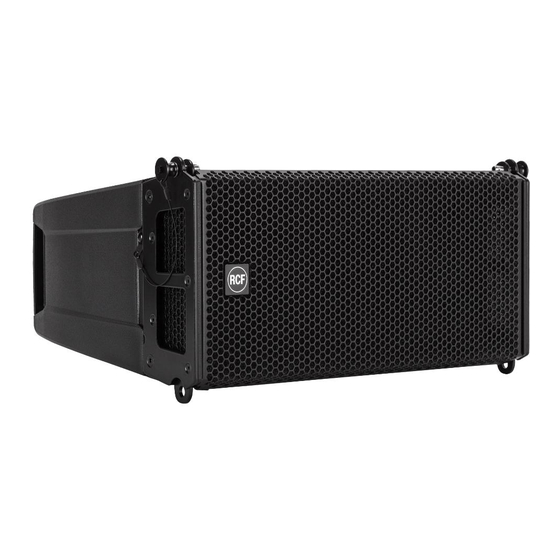
(wall, ceiling, structure, etc.), and the components used for attachment (screw anchors, screws, brackets not supplied by RCF etc.), which must guarantee the security of the system / installation over time, also considering, for example, the mechanical vibrations normally generated by transducers. - Page 5 THE HDL 12-AS The HDL 12-AS is the companion subwoofer for HDL 6-A. Housing a 12” woofer, the HDL 12-AS, is a very compact active sub enclosure and features a 1400 W powerful digital amplifier. It is the ideal complement to create flown HDL 6-A clusters with outstanding performance.
-
Page 6: Rigging The System
Country and local laws and regulations. • Always check that all the parts of the rigging system that are not provided from RCF are: -appropriate for the application... - Page 7 HDL 6-A arrays’ mechanics are built with certified UNI EN 10025 Steel. RCF prediction software calculates forces on every single stressed part of the assembly and shows the minimum safety factor for every link. Structural steel has a stress-strain (or...
- Page 8 The optimal setting of a loudspeaker array cannot ignore the basics of acoustics and the awareness that many factors contribute to a sonic result that matches expectations. RCF provides the user with simple instruments that help the setting of the system in an easy and reliable way.
- Page 9 The software was developed with Matlab 2015b and requires Matlab programming libraries. At the very first installation user should refer to the installation package, available from the RCF website, containing the Matlab Runtime (ver. 9) or the installation package that will download the Runtime from the web. Once the libraries are correctly installed, for all the following version of the software the user can directly download the application without the Runtime.
- Page 11 After the choice of folders for HDL6-SahpeDesigner software (Figure 2) and Matlab Libraries Runtime the installer takes a couple of minutes for the installation procedure.
- Page 12 DESIGN THE SYSTEM The HDL6 Shape Designer software is divided into two macro sections: the left part of the interface is dedicated to project variables and data (size of audiences to cover, height, number of modules, etc.), the right part shows the processing results.
-
Page 13: Recommended Workflow
RECOMMENDED WORKFLOW Pending the official and definitive simulation software, RCF recommends the use of HDL6 Shape Designer together with Ease Focus 3. Because of the need of interaction between different software, the recommended workflow assumes the following steps for every array in the final project: - Shape Designer: audience and array setup. - Page 14 RIGGING COMPONENTS Description Accessory p/n BARRA SOSPENSIONE HDL6-A E HDL12-AS 13360360 - up to 16 HDL6-A - up to 8 HDL12-AS - up to 4 HDL12-AS + 8 HDL6-A QUICK LOCK PIN 13360022 FLY BAR PICK UP HDL6-A 13360372 CONNECTION BRACKET FOR SECURELY LOCKING THE STACKING CLUSTER ON A SUBWOOFER POLE MOUNT BRACKET...
- Page 15 13360129 HOIST SPACING CHAIN. It allows enough space for the hang of most 2 motor chain containers and avoids any impact on the vertical balance of the array when it is suspended from a single pick-up point. 13360372 FLY BAR PICK UP HDL6-A + 2 QUICK LOCK PIN (SPARE PART P/N 13360022) 13360351 AC 2X AZIMUT PLATE.
-
Page 16: Rigging Procedure
RIGGING PROCEDURE Installation and setup should only be carried out by qualified and authorized personnel observing the valid national Rules for the Prevention of Accidents (RPA). It is the responsibility of the person installing the assembly to ensure that the suspension/fixing points are suitable for the intended use. - Page 17 1. FLYBAR SETUP The HDL6 flybar allows to set the central bar in two different configurations “A” e “B”. Configuration “B” allows a better upper inclination of the cluster. FLYBAR WITH CENTRAL BAR IN “A” POSITION FLYBAR WITH CENTRAL BAR IN “B”...
- Page 18 PICK UP POINT 1.2 PICK UP POINT POSITION “B” POSITION UP POINT POINT ITION POSITION P POINT SITION PICK UP POINT PICK UP POINT PICK UP POINT “B” POSITION “B” POSITION “A” POSITION PICK UP POINT POSITION P POINT SITION PICK UP POINT PICK UP POINT 2.
- Page 19 2.1 SECURING THE FLYBAR TO THE FIRST HDL6-A SPEAKER 1. Insert the frontal quick lock pins “F” 2. Rotate the rear bracket and secure it to the flybar with the rear quick lock pin “S” to the HDL6 Link Point hole 2.2 SECURING THE SECOND HDL6-A SPEAKER TO THE FIRST (AND CONSECUTIVE) 1.
- Page 20 2.3 SECURING THE FLYBAR TO THE FIRST HDL12-AS SPEAKER 1. Insert the frontal quick lock pins “F” 2. Rotate the rear bracket and secure it to the flybar with the rear quick lock pin “S” on the HDL12 Link Point hole. 2.4 SECURING THE SECOND HDL12-AS SPEAKER TO THE FIRST (AND CONSECUTIVE): 1.
- Page 21 2.5 CLUSTER HDL12-AS + HDL6-A 1. Using the quick lock pin “P”, secure the linking bracket to the HDL6-A speaker on the “Link point to HDL12-AS” hole, on the rear bracket. 2. Rotate the HDL6-A rear bracket and block it on the linking bracket between the two metal flaps. 1.
- Page 22 3. STACKING PROCEDURE Remove the central bar “A” from the flybar by pulling out the linchpins “X” and the quick lock pins “S”. 3.1 STACKING ON SUB HDL12-AS 1. Secure the flybar to HDL12-AS 2. Secure the stacking bar“B” (as shown in the picture) to the flybar using the quick lock pin “S” (follow the indication “stacking point”) 1.
- Page 23 2. Select the inclination angle (positive angles indicate a lower inclination of the speaker) and secure it with the rear quick lock pin “P”. WARNING: ALWAYS VERIFY THE SYSTEM SOLIDITY IN EVERY CONFIGURATION 3.1 STACKING ON DIFFERENT SUBWOOFERS (OTHER THAN HDL12-AS) 1.
- Page 24 3.2 GRAOUND STACKING 1. Screw all three plastic feet “P”. 2. Adjust the feet to stabilize the flybar on the subwoofer then block them with thieir nuts to avoid unscrewing. 3. Assemble the HDL6-A speaker with the same procedure. WARNING: ALWAYS VERIFY THE SYSTEM SOLIDITY IN EVERY CONFIGURATION 3.3 POLE MOUNTING WITH SUSPENSION BAR 1.
- Page 25 3.4 POLE MOUNTING WITH POLE MOUNT 3X HDL 6-A 1. Secure the flybar on the pole by screwing the knob “M” 2. Assemble the speakers HDL6-A with the same procedure used on stacking on sub HDL12-AS WARNING: ALWAYS VERIFY - THE SYSTEM SOLIDITY IN EVERY CONFIGURATION - THE POLE PAYLOAD 4.
- Page 26 During transportation ensure the rigging components are not stressed or damaged by mechanical forces. Use suitable transport cases. We recommend the use of the RCF HDL6-A touring kart for this purpose. Due to their surface treatment the rigging components are temporarily protected against moisture. However, ensure the components are in a dry state while stored or during transportation and use.
-
Page 27: Specifications
SPECIFICATIONS HDL 6-A HDL 12-AS Frequency Response 65 Hz - 20 kHz 40 Hz - 120 kHz Max Spl 131 dB 131 dB Horizontal Coverage Angle 100° Vertical Coverage Angle 10° Compression Driver 1.0” neo, 1.7”v.c. Woofer 2 x 6.0” neo, 2.0”v.c. - Page 28 RCF SpA: Via Raffaello, 13 - 42124 Reggio Emilia - Italy tel. +39 0522 274411 - fax +39 0522 274484 - e-mail: rcfservice@rcf.it...
Need help?
Do you have a question about the HDL 12-AS and is the answer not in the manual?
Questions and answers