Table of Contents
Advertisement
Quick Links
Advertisement
Table of Contents

Subscribe to Our Youtube Channel
Related Manuals for RCF HDL18-AS


Summary of Contents for RCF HDL18-AS
- Page 1 OWNER MANUAL HDL18-AS ACTIVE FLYABLE HIGH POWER SUBWOOFER...
- Page 2 LANGUAGE LANGUAGE ENGLISH ENGLISH...
-
Page 3: Safety Precautions
(wall, ceiling, structure, etc.), and the components used for attachment (screw anchors, screws, brackets not supplied by RCF etc.), which must guarantee the security of the system / installation over time, also considering, for example, the mechanical vibrations normally generated by transducers. -
Page 4: Important Notes
RCF S.p.A. will not assume any responsibility for the incorrect installation and / or use of this product. -
Page 5: Product Informations
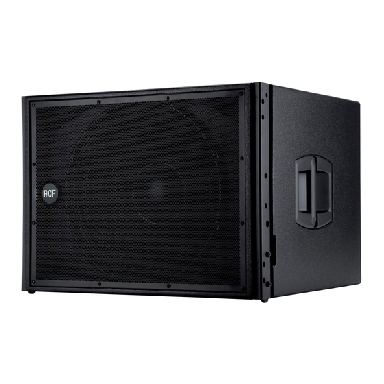
ACTIVE FLYABLE HIGH POWER SUBWOOFER POWER SUBWOOFER The HDL18-AS is a compact, flyable high power subwoofer, designed to integrate seemlessly into a HDL 20-A flown array. The bass reflex design guarantees a deep, linear power response while the 4” voice coil vented design woofer offers the minimum of power compression. -
Page 6: Rear Panel
- LINK (daisy chain the input signal). - ON (add the crossover filter to the output signal). AC POWERCON RECEPTACLE. RCF D Line uses a POWERCON locking 3-pole AC mains. Always use the specific power cord provided in the package. - Page 7 Always make sure that the maximum current requirement does not exceed the maximum admitted POWERCON current. In case of doubt call the closest RCF SERVICE CENTRE. POWER MAIN SWITCH. The power switch turns the AC power ON and OFF. Make sure that the VOLUME is set to - when you turn on the speaker.
-
Page 8: Installation
WARNING: always make sure that the maximum current requirement does not exceed WARNING the maximum admitted POWERCON current. In case of doubt call the closest RCF service centre. MAINS SUPPLY The system accept mains supply voltage115-230 (+15/-15%) V ~ 230 VOLT, 50 Hz SETUP : FUSE VALUE T 1.6 A - 250V... - Page 9 HDL18-AS mechanics are built with certified UNI EN 10025-95 S 235 JR and S 355 JR Steel. RCF prediction software calculates forces on every single stressed part of the assembly and shows the minimum safety factor for every link.
- Page 10 B position allows an intermediate step using the same fixing holes. Move the pickup bracket in the position suggested by RCF Shape Designer. Fix the pickup bracket with the two pins on the bracket’s lanyard to lock the pickup.
- Page 11 A (2:1) 4) Reverse and connect the rear bracket to the fly-bar using 1 quick lock pins. The first HDL18-AS has to be fixed always starting at 0° with respect of the frame. No other angles are allowded. 5) Connect the second cabinet to the first always starting from the 2 front brackets.
- Page 12 6) Reverse and connect the rear bracket of the second cabinet using the hole. 7) Connect all the other HDL20-A cabinets using the accessory linkbar HDL18 to HDL20A (P.N. 13360225). Fix the linkbar P.N. 13360225 to the HDL 18-AS rear bracket using 2 pins (1 on the subwoofer and 1 on the accessory).
- Page 13 (crucial in aiming the array) for a given venue, will be explained later in this Guide. ARRAY SYSTEMS DESIGN RCF Shape Designer is supplied in a zip folder which contains a setup executable file: INSTALLING RCF SHAPE DESIGNER Double-click on this and follow the on-screen prompts.
-
Page 14: Computer Requirements
Various venue dimensions are entered that allow the RCF Shape Designer to calculate the resultant array performance. USING RCF SHAPE DESIGNER Once you have installed RCF Shape Designer, it will be visible as a shortcut in All Programs via your Windows Start button. SOFTWARE... -
Page 15: Array Installation
ENTERING VENUE DATA For best results, planes should be used as follows: FLOOR is used to simulate the main floor area from the stage to a rear bleacher or boundary. PLANE 1 is used to simulate any audience continuation behind FLOOR (e.g. a rear bleacher) from the end of the main floor to furthest and highest seat below PLANE 2. -
Page 16: Suspended Mode
Number of cabinets can be set depending also on cabs availability. SUBWOOFERS HDL20-A VENUE PAGE RCF SHAPE DESIGNER RESULTS - Graphical representations of the array and the venue - Aiming splay angle between each pair of enclosures ARRAY PAGE - Height of the array and trim height to the bottom of the array from the floor... - Page 17 MECHANICS PAGE - Cluster Mechanical specifications - Mechanical safety factors PROCESSOR PAGE - DSP preset configuration SPL & REPORT PAGE - On-axis aiming angle for each enclosure as a difference from 0° horizontal - Various angles and throw distances calculated from the venue’s dimensions - DSP preset configuration - SPL representation on the audience area WARNING...
-
Page 18: Manual Mode
MANUAL MODE RCF Shape Designer works in either of two basic ways: - AUTOMATIC MODE (default setting): The RCF Shape Designer will select the optimum enclosure splays, array aiming angle, fly-bar pick point and DSP preset configurations. - MANUAL MODE: This provides a partial control over the array’s configuration. The enclosure splays can be increased with a progression of 2°... -
Page 19: Specifications
± SPECIFICATIONS µ ÷ ACOUSTICAL Operating frequency range Frequency Response -3 dB: 30 Hz ÷ 140 kHz Max SPL Max SPL: 135 dB Crossover point Woofer: 18”, 4.0” v.c. INPUT/OUTPUT SECTION Input signal bal/unbal Input connectors Output connectors Input sensitivity -2 dBu / +4 dBu PROCESSOR SECTION Protections... - Page 20 HEADQUARTERS: RCF S.p.A. Italy tel. +39 0522 274 411 e-mail: info@rcf.it RCF UK tel. 0844 745 1234 Int. +44 870 626 3142 e-mail: info@rcfaudio.co.uk RCF France tel. +33 1 49 01 02 31 e-mail: france@rcf.it RCF Germany tel. +49 2203 925370 e-mail: germany@rcf.it...
Need help?
Do you have a question about the HDL18-AS and is the answer not in the manual?
Questions and answers