Table of Contents
Advertisement
Quick Links
Advertisement
Table of Contents

Related Manuals for Harman dbx 676


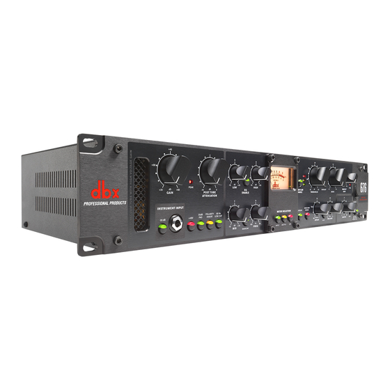
Summary of Contents for Harman dbx 676
- Page 1 TU B E M I C C H AN N E L S TR I P Owner’s Manual...
- Page 2 TU B E M I C CHAN N E L STR I P Warranty 1. Please register your product online at www.dbxpro.com. Proof-of-purchase is considered to be the responsibility of the consumer. A copy of the original purchase receipt must be provided for any warranty service. 2.
-
Page 3: Table Of Contents
TU B E M I C CHAN N E L S TR I P Table of Contents Overview ����������������������������������������������������������������������� 2 Introduction ������������������������������������������������������������������������������������������������� 2 Features ������������������������������������������������������������������������������������������������������� 3 Installation ������������������������������������������������������������������� 4 Installation Recommendations ��������������������������������������������������������������� 4 Making Connections �������������������������������������������������������������������������������� 4 Applying Power ����������������������������������������������������������������������������������������� 4 Quick Start ��������������������������������������������������������������������... -
Page 4: Overview
TU B E M I C CHAN N E L STR I P Overview Introduction The dbx 676 is a single-channel tube microphone preamplifier and channel strip processor with 3-band semi-parametric ® EQ, compressor, and PeakPlus™ limiter. When used at the front of a digital audio workstation, tracks will take on more analog warmth and sheen when compared to preamps built into standard audio recording interfaces. -
Page 5: Features
TU B E M I C CHAN N E L S TR I P Features • Discrete, Class A, High-Voltage Tube Microphone Preamplifier • 60 dB of Preamplifier Gain • +48V Phantom Power • 20 dB Pad • Polarity Invert Switch •... -
Page 6: Installation
TU B E M I C CHAN N E L STR I P Installation Installation Recommendations FOR RACK MOUNT USE ONLY. Install the 676 in a standard 19” rack with the provided rack screws. The 676 should not be mounted above or below anything that generates excessive heat. Ambient temperatures should not exceed 95ºF (35ºC) when equipment is in use. -
Page 7: Quick Start
TU B E M I C CHAN N E L S TR I P Quick Start Follow these steps to get up and running fast: Turn the control all the way down. 1� POST ATTENUATION Engage the button if connecting a bass or guitar to the INSTRUMENT INPUT jack on the front 2�... -
Page 8: The User Interface & Connectors
TU B E M I C CHAN N E L STR I P The User Interface & Connectors Front Panel 1.5:1 1.2:1 – PEAK HIGH PEAK ∞ ∞ ∞ MAKEUP COMP/LIM OVEREASY GAIN POST TUBE ENABLE ENABLE THRESHOLD RATIO GAIN ATTENUATION INSTRUMENT INPUT POWER... -
Page 9: Rear Panel
TU B E M I C CHAN N E L S TR I P Rear Panel 1. Power Connector Connect the included IEC power cord to this connector and the other end to an available AC outlet. 2. Fuse Drawer This drawer houses the main power fuse as well as a replacement fuse, see ‘Replacing The Fuse’... -
Page 10: The Preamp Section
TU B E M I C CHAN N E L STR I P The Preamp Section 1.5:1 1.2:1 – PEAK HIGH PEAK ∞ ∞ ∞ MAKEUP COMP/LIM OVEREASY GAIN POST TUBE ENABLE ENABLE THRESHOLD RATIO GAIN ATTENUATION INSTRUMENT INPUT POWER 1.5k 20dB POLARITY... -
Page 11: Preamp Example Settings
TU B E M I C CHAN N E L S TR I P 9. 80 Hz Low Cut Button Engage this button to roll-off frequencies below 80 Hz from passing through the 676. This can help reduce low-frequency noise from microphone vibrations, etc.. This low cut filter is an filter. Preamp Example Settings The below settings are designed to be used as a starting point. -
Page 12: The Eq Section
TU B E M I C CHAN N E L STR I P The EQ Section The 676 semi-parametric EQ provides a way to make broad tonal adjustments on the source. Of course it’s best to fix a tonal issue at the mic by adjusting the mic placement, trying different mic polar patterns, or swapping the mic for another. However, if you must make a mic work for the occasion and have already done all of these things then reaching for the EQ just may be what’s needed. -
Page 13: Eq Example Settings
TU B E M I C CHAN N E L S TR I P EQ Example Settings The below settings are designed to be used as a starting point. Your results using these settings will vary depending on the variables inherent in your application. For best results, adjust the settings to suit your application as described in the section following the below examples. -
Page 14: The Compressor & Limiter Section
TU B E M I C CHAN N E L STR I P The Compressor & Limiter Section These days, deciding whether or not to compress a signal while tracking is a matter of personal preference. It was common practice in the days of analog tape to keep the lower-level portions of an audio signal well above the noise floor inherent in magnetic tape. - Page 15 TU B E M I C CHAN N E L S TR I P The PeakPlus limiter uses Intelligent Predictive Limiting to determine how much gain reduction to apply and can be used for level-critical applications, where you want to keep dynamics under control no matter how loud the source becomes. 1.5:1 1.2:1 –...
- Page 16 TU B E M I C CHAN N E L STR I P input to output ratio, meaning no compression would be applied. Use lower settings for gentle compression and higher settings for heavier compression or limiting. 6. Makeup Gain Control [-20 dB to +20 dB] This control adjusts the gain post-compression and pre-limiter.
- Page 17 TU B E M I C CHAN N E L S TR I P 12. Release Control [4000 dB/sec - 10 dB/sec] This control adjusts the amount of time it takes the compressor to recover from compression. 4000 dB/sec is the fastest release setting.
-
Page 18: Compressor/Limiter Example Settings
TU B E M I C CHAN N E L STR I P Compressor/Limiter Example Settings The below settings are designed to be used as a starting point. Your results using these settings will vary depending on the variables inherent in your application. For best results, adjust the settings to suit your application as described in the section following the below examples. -
Page 19: Setting The Compressor/Limiter
TU B E M I C CHAN N E L S TR I P Setting The Compressor/Limiter Start by setting all settings as shown below: 1� 1.5:1 1.2:1 – PEAK ∞ MAKEUP COMP/LIM OVEREASY ENABLE THRESHOLD RATIO GAIN POWER 1.5k SIDECHAIN DIGITAL METER SELECTION... -
Page 20: Parallel Compression
TU B E M I C CHAN N E L STR I P Parallel Compression Compression is typically applied as a serial process – meaning the entire signal is processed by the compressor. This is sometimes referred to as ‘downward compression’ . By applying make-up gain, the compressed signal can then be raised to restore the signal’s average level to what it was before applying compression, hence the term ‘make-up gain’... -
Page 21: Application Guide
TU B E M I C CHAN N E L S TR I P Application Guide Direct Instrument Recording Application Use this configuration to record the direct signal from an electric guitar or bass using the 676’s Hi-Z INSTRUMENT INPUT. In this configuration the direct signal will still pass through the tube gain stage, making it great for recording harmonically-rich bass and guitar tracks! Application Notes:... -
Page 22: Mic Preamp Application
TU B E M I C CHAN N E L STR I P Mic Preamp Application Use this configuration for recording vocals or an acoustic instrument using a microphone. It is also applicable for live sound use when connecting a mic or direct instrument signal using a D.I. box located on-stage. Application Notes: •... -
Page 23: Sidechain Application
TU B E M I C CHAN N E L S TR I P Sidechain Application Use this configuration to use the 676’s built-in compressor as a de-esser. De-essing is typically used to reduce the level of ‘sibilant’ frequencies in vocals, which can make them sound abrasive and unpleasant. Excess sibilance can be caused by compression, mic selection and/or placement, or by the vocalist’s technique. -
Page 24: Using The 676 Compressor At Mixdown
TU B E M I C CHAN N E L STR I P Using The 676 Compressor At Mixdown It is possible to use the 676 compressor during the mixing stage if your audio interface has a spare line output, available line input, and decent-quality A/D and D/A converters. -
Page 25: Technical Information
TU B E M I C CHAN N E L S TR I P Technical Information Block Diagram... -
Page 26: Compression Graphs
TU B E M I C CHAN N E L STR I P Compression Graphs Ratio OverEasy ® OverEasy ® 1:1 Unity Above Threshold 20:1 ∞ Rotation Point Threshold − 5 Above Threshold Threshold OverEasy Range − 10 GREEN Below Threshold −... -
Page 27: Audio Cable Diagrams
TU B E M I C CHAN N E L S TR I P Audio Cable Diagrams TO NEXT DEVICE (INPUT) TO NEXT DEVICE (INPUT) FROM SOURCE DEVICE (OUTPUT) FROM SOURCE DEVICE (OUTPUT) RING SLEEVE SLEEVE RING (COLD -) (GROUND) (GROUND) (COLD -) HOT +... -
Page 28: Replacing The Tube
TU B E M I C CHAN N E L STR I P Replacing The Tube INSTRUCTIONS FOR QUALIFIED SERVICE PERSONNEL: CAUTION! These servicing instructions are for use by qualified service personnel only. To reduce the risk of electric shock, do not perform any servicing other than that contained in the operating instructions unless you are qualified to do so. -
Page 29: Replacing The Fuse
TU B E M I C CHAN N E L S TR I P Replacing The Fuse The power fuse is located in the drawer at the bottom of the IEC power inlet on the back panel of the 676. From the factory, there will be two fuses in this drawer. -
Page 30: Specifications
TU B E M I C CHAN N E L STR I P Specifications... - Page 31 CLASS “A” VACUUM TUBE WITH HIGH VOLTAGE GAIN...
- Page 32 Phone: (801) 566-8800 Website: dbxpro.com Support: dbxpro.com/en-US/support dbx Professional Products is a registered trademark of Harman 676 Owner’s Manual Rev A © 2015 Harman All rights reserved...
Need help?
Do you have a question about the dbx 676 and is the answer not in the manual?
Questions and answers