Table of Contents
Advertisement
SPECIFICATIONS
Power source
Nominal input power
Vacuum
Power cord length
Radio of operation
Net weight
Dimensions (LxWxH) mm
Attachments:
Dusting brush
Upholstery nozzle
Crevice nozzle
Extension wand
Specifications are subject to change without notice for further improvement.
MODELS MC-E581K / MC-E582K / MC-E583K
MC-E581K
MC-E582K
MC-E581
MC-E582
AC230-240V
AC230-240V
50Hz
50Hz
1200-1300W
1300-1400W
18 kPa
18 kPa
7.5 m
7.5 m
7.5 m
7.5 m
8.1 kg
8.1 kg
360x305x1100
360x305x1100
•
•
•
•
•
•
•
•
MC-E581 / MC-E582 / MC-E583
MC-E583K
MC-E583
AC230-240V
50Hz
1300-1400W
18 kPa
7.5 m
7.5 m
8.2 kg
360x305x1100
•
•
•
•
Ref.: Z32W1000
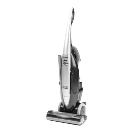
Vacuum Cleaner
Matsushita Electric España, S.A.
DIVISION DE ASPIRADORAS
Zona Industrial del Polígono de CELRÀ
17460 CELRÀ (Girona) SPAIN
Advertisement
Table of Contents

Related Manuals for Panasonic MC-E581K


Summary of Contents for Panasonic MC-E581K
-
Page 1: Vacuum Cleaner
Ref.: Z32W1000 Vacuum Cleaner MODELS MC-E581K / MC-E582K / MC-E583K MC-E581 / MC-E582 / MC-E583 SPECIFICATIONS MC-E581K MC-E582K MC-E583K MC-E581 MC-E582 MC-E583 Power source AC230-240V AC230-240V AC230-240V 50Hz 50Hz 50Hz Nominal input power 1200-1300W 1300-1400W 1300-1400W Vacuum 18 kPa 18 kPa... -
Page 2: Replacement Of Main Parts
REPLACEMENT OF MAIN PARTS IMPORTANT: Before replacing any part always Beater bar pedal DISCONNECT THE CLEANER FROM THE ELECTRICITY SUPPLY. • BEATER BAR UNIT / BEATER BAR MOTOR / BEATER BAR SIDE BRUSH (1) Beater bar unit 1. Remove beater bar pedal (Fig. 1) Fig. - Page 3 REMPLACEMENT OF MAIN PARTS 4. Remove 8 screws from the base plate and lift it off. (Fig. 4) Base plate Beater bar unit Fig. 4 5. Take out beater bar unit and remove two connections and beater bar support from the motor. (Fig. 5) Beater bar unit IMPORTANT: When removing the two lead wires (provided with quick-connect terminal) from the beater bar motor,...
- Page 4 REPLACEMENT OF MAIN PARTS 6. Replace beater bar unit with a new one. Reinstall beater bar support in the proper motor position and connect the two lead wires to the motor terminals. IMPORTANT: Make sure the lead wires are correctly positioned to avoid be pinched between bodies.
- Page 5 REPLACEMENT OF MAIN PARTS • BEATER BAR THERMAL CUT-OUT / ON /OFF SWITCH / OVER-CURRENT CIRCUIT BREAKER / Beater bar support SAFETY SWITCH (1) Beater bar Thermal cut-out 1. Remove base plate as explained previously in paragraph (1) "Beater bar unit", points 1-4. 2.
- Page 6 REPLACEMENT OF MAIN PARTS • MOTOR / CARBON BRUSH / THERMAL CUT-OUT (1) Motor Suction pipe inlet 1. Remove base plate as explained previously in paragraph (1) "Beater bar unit", points 1-4. 2. Remove the screws from the suction pipe inlet and upper body and take them out.
- Page 7 REPLACEMENT OF MAIN PARTS 4. Remove front and rear motor support and replace the motor with a new one. Front motor support 5. Reassemble front and rear motor support in the new motor and connect the two lead wires to the carbon brush holder Motor terminals.
- Page 8 REPLACEMENT OF MAIN PARTS • CORD REEL UNIT / POWER SUPPLY CORD Cord cover (1) Cord reel unit 1. Remove upper body as explained previously in paragraph Lead wires (1) "Motor", points 1-2. 2. Remove the power supply cord cover and disconnect the two lead wires (provided with quick-connect terminal) from the contact springs tabs.
- Page 9 1. Remove the screw from the handle and take it out. (Fig. 25) Fig. 25 2. Remove 5 screws from the switch cover and take it out. MC-E583K / MC-E583 Switch cover (Fig. 26) MC-E581K / MC-E582K MC-E581 / MC-E582 Switch cover Fig. 26...
- Page 10 REPLACEMENT OF MAIN PARTS 3. Take out power control assembly and remove connections MC-E583K / MC-E583 MC-E581K / MC-E582K from the power control circuit. (Fig. 27) MC-E581 / MC-E582 Remove Remove connections connections Fig. 27 Fig. 27 4. Replace the power control circuit with a new one and MC-E583K / MC-E583 connect the lead wires according to the schematic diagram.
- Page 11 IMPORTANT: Grasp the circuit lead wires with a fastener to avoid touching the circuit refrigerator. 4. Reinstall switch cover and handle. Remove connections Fig. 29 MC-E581K / MC-E582K MC-E581 / MC-E582 Fuse Remove connections Fig. 29 (3) Dust sensor circuit (MC-E583K / MC-E583 only) 1.
- Page 12 REPLACEMENT OF MAIN PARTS • HOSE UNIT 1. Remove hose connection pipe from the suction pipe inlet, Hose clip hose support and hose clip. (Fig. 31) Hose Hose support Connection pipe Suction pipe inlet Fig. 31 2. Remove handle and switch cover. (Fig. 32) 3.
-
Page 13: Troubleshooting Guide
TROUBLE SHOOTING GUIDE CONDITION CHECKPOINT METHOD OF INSPECTION CAUSE / REMEDY Vacuum cleaner Power supply cord Check power supply cord continuity. If there is no continuity, replace it. doesn’t work Fuse (Plug for UK only) Check fuse continuity. If there is no continuity, replace it. Thermal cut-out Check thermal cut-out continuity. - Page 14 M O T O R A B N O R M A L Works at AUTO position only Works at MAX position only Works at MIN position only (MC-E583K, MC-E583 only) Aspect of Aspect of Aspect of Replace Power Replace Power Replace Power Power control Power control...
-
Page 15: Packing Instructions
PACKING INSTRUCTIONS...
Need help?
Do you have a question about the MC-E581K and is the answer not in the manual?
Questions and answers