Table of Contents
Advertisement
Quick Links
Advertisement
Table of Contents

Related Manuals for Planet Networking & Communication LRP-822CS


Summary of Contents for Planet Networking & Communication LRP-822CS
-
Page 2: Fcc Warning
User’s Manual of LRP-822CS/LRP-1622CS Trademarks Copyright © PLANET Technology Corp. 2015. Contents are subject to revision without prior notice. PLANET is a registered trademark of PLANET Technology Corp. All other trademarks belong to their respective owners. Disclaimer PLANET Technology does not warrant that the hardware will work properly in all environments and applications, and makes no warranty and representation, either implied or expressed, with respect to the quality, performance, merchantability, or fitness for a particular purpose. -
Page 3: Table Of Contents
User’s Manual of LRP-822CS/LRP-1622CS TABLE OF CONTENTS 1. INTRODUCTION........................10 1.1 Packet Contents ............................10 1.2 Product Description ...........................11 1.3 How to Use This Manual ..........................16 1.4 Product Features............................16 1.5 Product Specifications ..........................19 2. INSTALLATION ........................23 2.1 Hardware Description ..........................23 2.1.1 Switch Front Panel ..............................23... - Page 4 User’s Manual of LRP-822CS/LRP-1622CS 4.2 System.................................50 4.2.1 System Information..............................50 4.2.2 IP Configurations ..............................51 4.2.3 IPv6 Configuration ...............................53 4.2.4 User Configuration...............................55 4.2.5 Time Settings...............................56 4.2.5.1 System Time..............................56 4.2.5.2 SNTP Server Settings ..........................59 4.2.6 Log Management..............................60 4.2.6.1 Local Log..............................60 4.2.6.2 Local Log..............................61 4.2.6.3 Remote Syslog ............................63...
- Page 5 User’s Manual of LRP-822CS/LRP-1622CS 4.4 Link Aggregation ............................102 4.4.1 LAG Setting ...............................104 4.4.2 LAG Managment ...............................105 4.4.3 LAG Port Setting..............................106 4.4.4 LACP Setting ..............................108 4.4.5 LACP Port Setting..............................109 4.4.6 LAG Status ................................ 110 4.5 VLAN................................113 4.5.1 VLAN Overview ..............................113 4.5.2 IEEE 802.1Q VLAN ............................
- Page 6 User’s Manual of LRP-822CS/LRP-1622CS 4.7.2.3 IGMP Static Group...........................171 4.7.2.4 IGMP Group Table ...........................172 4.7.2.5 IGMP Router Setting ..........................173 4.7.2.6 IGMP Router Table ..........................174 4.7.2.7 IGMP Forward All ............................175 4.7.3 IGMP Snooping Statics............................176 4.7.4 MLD Snooping..............................178 4.7.4.1 MLD Setting.............................178 4.7.4.2 MLD Static Group ............................180 4.7.4.3 MLD Group Table ............................181...
- Page 7 User’s Manual of LRP-822CS/LRP-1622CS 4.8.5.4 Telephony OUI Port Setting ........................213 4.9 Security ..............................215 4.9.1 802.1X ................................215 4.9.1.1 Understanding IEEE 802.1X Port-based Authentication................216 4.9.1.2 802.1X Setting ............................219 4.9.1.3 802.1X Port Setting ..........................220 4.9.1.4 Guest VLAN Setting ..........................222 4.9.1.5 Authenticated Host ..........................225 4.9.2 RADIUS Server ..............................225...
- Page 8 User’s Manual of LRP-822CS/LRP-1622CS 4.9.9.1 Port Settings ............................264 4.9.9.2 Binding Table ............................265 4.9.10 Port Security ..............................267 4.9.11 DoS..................................269 4.9.11.1 Global DoS Setting ..........................269 4.9.11.2 DoS Port Setting ............................272 4.9.12 Storm Control..............................274 4.9.12.1 Global Setting ............................274 4.9.12.2 Port Setting............................275 4.10 ACL ................................277 4.10.1 MAC-based ACL ..............................277...
- Page 9 User’s Manual of LRP-822CS/LRP-1622CS 4.14 RMON...............................321 4.14.1 RMON Statistics ..............................321 4.14.2 RMON Event ..............................323 4.14.3 RMON Event Log ............................324 4.14.4 RMON Alarm ..............................325 4.14.5 RMON History ..............................328 4.14.6 RMON History Log ............................329 4.15 Power over Ethernet ..........................330 4.15.1 Long Reach Power over Ethernet Powered Device..................331 4.15.2 System Configuration ............................332...
-
Page 10: Introduction
Power Cord x 1 RS232 to RJ45 Console Cable x 1 SFP Dust Cap x 2 BNC Female Dust Cap x 8 (LRP-822CS) BNC Female Dust Cap x 16 (LRP-1622CS) Warning Sticker x 8 (LRP-822CS) ... -
Page 11: Product Description
Multi-channel Long Reach Power over Ethernet To support the enterprises in easily building a multi-channel and centrally-controlled Long Reach PoE system, the LRP-822CS works with the Long Reach PoE Extenders, LRP-101CE, via its BNC ports being the Long Reach PoE injectors for all connected LRP Extenders. - Page 12 User’s Manual of LRP-822CS/LRP-1622CS Centralized Power Management PLANET LRP Managed Switch eliminates the need for an additional remote site power while allowing a single power source to provide power to both LRP extenders and the PoE powered devices at long range. The Long Reach PoE capabilities provided help to reduce installation time and deployment costs for network devices as a result of freeing from restrictions of power outlet locations.
- Page 13 User’s Manual of LRP-822CS/LRP-1622CS Scheduled Power Recycling PLANET LRP Managed Switch allows each of the connected PoE IP cameras or PoE wireless access points via the LRP-101CE to reboot at a specific time each week. Therefore, it will reduce the chance of IP camera or wireless AP crash resulting from buffer overflow.
- Page 14 User’s Manual of LRP-822CS/LRP-1622CS Environment-friendly, Smart Fan Design for Silent Operation PLANET LRP Managed Switch features a 19-inch metal housing, a low noise design and an effective ventilation system. It supports the smart fan technology to automatically control the speed of the built-in fan to reduce noise and maintain the temperature of the PoE switch for optimal power output capability.
- Page 15 User’s Manual of LRP-822CS/LRP-1622CS Advanced Network Security PLANET LRP Managed Switch also provides DHCP Snooping, IP Source Guard and Dynamic ARP Inspection functions to prevent IP snooping from attack and discard ARP packets with invalid MAC address. The network administrators can now build highly-secured corporate networks with considerably less time and effort than before.
-
Page 16: How To Use This Manual
User’s Manual of LRP-822CS/LRP-1622CS 1.3 How to Use This Manual This User Manual is structured as follows: Section 2, INSTALLATION The section explains the functions of the Switch and how to physically install the LRP Managed Switch. Section 3, SWITCH MANAGEMENT The section contains the information about the software function of the LRP Managed Switch. - Page 17 User’s Manual of LRP-822CS/LRP-1622CS Layer 2 Features ■ Prevents packet loss with back pressure (half-duplex) and IEEE 802.3x pause frame flow control (full-duplex) ■ High performance Store and Forward architecture, broadcast storm control, runt/CRC filtering that eliminates erroneous packets to optimize the network bandwidth ■...
- Page 18 User’s Manual of LRP-822CS/LRP-1622CS Security ■ Authentication IEEE 802.1x port-based network access authentication Built-in RADIUS client to co-operate with the RADIUS servers RADIUS/TACACS+ login user access authentication ■ Access Control List IPv4/IPv6 IP-based ACL MAC-based ACL ■...
-
Page 19: Product Specifications
User’s Manual of LRP-822CS/LRP-1622CS 1.5 Product Specifications Model LRP-822CS LRP-1622CS Hardware Specifications 2 x 10/100/1000BASE-T RJ45 Copper Auto-negotiation/ Auto-MDI/MDI-X Ethernet 2 x 100/1000BASE-X SFP slot Fiber Optic Interfaces Supports 100/1000Mbps dual mode and DDM 10Kbytes with GE1 to GE4 Jumbo Frame... - Page 20 * The actual data rate and PoE output vary on the quality of the copper wire and environmental factors. The performance result above is based on the testing via the RG-6/U coaxial cable. ** TX: LRP-822CS to LRP-101CE; RX: LRP-101CE to LRP-822CS. Up to 4 LRP extenders within 1km RG-6/U coaxial cable* Multiple Nodes * The actual extender nodes vary on the quality of the copper wire and environmental factors.
- Page 21 User’s Manual of LRP-822CS/LRP-1622CS Many-to-1 monitor 802.1Q tagged-based VLAN Up to 256 VLAN groups, out of 4094 VLAN IDs 802.1ad Q-in-Q tunneling Voice VLAN VLAN Protocol VLAN Private VLAN (Protected port) GVRP IEEE 802.3ad LACP and static trunk Link Aggregation...
- Page 22 User’s Manual of LRP-822CS/LRP-1622CS RFC 2819 RMON (1, 2, 3, 9) RFC 2863 Interface Group MIB RFC 3635 Ethernet-like MIB Standards Conformance FCC Part 15 Class A, CE Regulation Compliance IEEE 1901 Broadband Power Line IEEE 802.3 10BASE-T IEEE 802.3u 100BASE-TX/100BASE-FX IEEE 802.3z Gigabit SX/LX...
-
Page 23: Installation
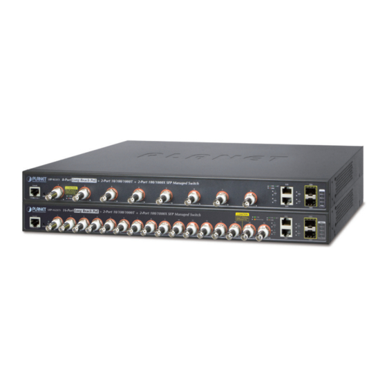
Figures 2-1-1A and 2-1-1B show the front panels of the LRP Managed Switches. Front Panel Figure 2-1-1A LRP-822CS Front Panel Front Panel Figure 2-1-1B LRP-1622CS Front Panel ■ Long Reach PoE BNC Interface BNC female port, 5C2V/RG6 75Ω coaxial cable: Up to 1 kilometer. - Page 24 User’s Manual of LRP-822CS/LRP-1622CS ■ Console Port The console port is a RJ45 port connector. It is an interface for connecting a terminal directly. Through the console port, it provides rich diagnostic information including IP Address setting, factory reset, port management, link status and system setting.
-
Page 25: Led Indications
The front panel LEDs indicates instant status of port links, data activity and system power; it helps monitor and troubleshoot when needed. Figures 2-1-2A and 2-1-2B show the LED indications of these LRP Managed Switches. LRP-822CS LED Indication Figure 2-1-2 LRP-822CS LED Panel ■ System / Alert Color Function Lights to indicate that the Switch has power. - Page 26 User’s Manual of LRP-822CS/LRP-1622CS ■ 1000BASE-SX/LX SFP Interfaces (GE3 to GE4) Color Function To indicate the link through that port is successfully established. Lights LNK/ACT Green Blinking To indicate that the switch is actively sending or receiving data over that port.
-
Page 27: Switch Rear Panel
Figure 2-1-3 shows the rear panel of these LRP Managed Switches. Rear Panel Figure 2-1-3 Rear Panel of LRP-822CS/LRP-1622CS ■ AC Power Receptacle For compatibility with electric service in most areas of the world, the LRP Managed Switch’s power supply automatically adjusts to line power in the range of 100-240V AC at 50/60 Hz. -
Page 28: Installing The Switch
User’s Manual of LRP-822CS/LRP-1622CS 2.2 Installing the Switch This section describes how to install your LRP Managed Switch and make connections to the LRP Managed Switch. Please read the following topics and perform the procedures in the order being presented. To install your LRP Managed Switch on a desktop or shelf, simply complete the following steps. -
Page 29: Rack Mounting
User’s Manual of LRP-822CS/LRP-1622CS Supply power to the LRP Managed Switch. Step 5: Connect one end of the power cable to the LRP Managed Switch. Connect the power plug of the power cable to a standard wall outlet. When the LRP Managed Switch receives power, the Power LED should remain solid Green. -
Page 30: Installing The Sfp Transceiver
User’s Manual of LRP-822CS/LRP-1622CS Figure 2-1-6 Mounting LRP Managed Switch in a Rack Proceeds with Steps 4 and 5 of session 2.2.1 Desktop Installation to connect the network cabling and supply power to Step 6: the LRP Managed Switch. 2.2.3 Installing the SFP transceiver The sections describe how to insert an SFP transceiver into an SFP slot. - Page 31 User’s Manual of LRP-822CS/LRP-1622CS Gigabit SFP Transceiver Modules SFP-Port 1000BASE-T Module MGB-GT SFP-Port 1000BASE-SX mini-GBIC module MGB-SX SFP-Port 1000BASE-LX mini-GBIC module MGB-LX SFP-Port 1000BASE-LX mini-GBIC module – 50km MGB-L50 SFP-Port 1000BASE-LX mini-GBIC module – 70km MGB-L70 ...
- Page 32 User’s Manual of LRP-822CS/LRP-1622CS Connect the Fiber Cable Insert the duplex LC connector into the SFP transceiver. Connect the other end of the cable to a device with SFP transceiver installed. Check the LNK/ACT LED of the SFP slot on the front of the LRP Managed Switch. Ensure that the SFP transceiver is operating correctly.
-
Page 33: Installing The Long Reach Poe Communication
User’s Manual of LRP-822CS/LRP-1622CS 2.2.4 Installing the Long Reach PoE Communication The sections describe how to insert a coaxial cable into a BNC female port. You can plug in and out the coaxial cable to/from any BNC female port without having to power down the LRP Managed Switch. - Page 34 User’s Manual of LRP-822CS/LRP-1622CS Tighten the BNC male connector gently. Figure 2-1-8 How to insert the coaxial cable from LRP Managed Switch Enable Long Reach Power over Ethernet function for the all LRP ports from WebUI Check the LNK LED of the Long Reach Power over Ethernet interface on the front of the LRP Managed Switch. Ensure...
- Page 35 User’s Manual of LRP-822CS/LRP-1622CS Remove the connected the Coaxial Cable Make sure there is no network activity anymore. Disable Long Reach Power over Ethernet function for the all LRP ports from WebUI. Loosen the BNC male connector gently. Pull out the coaxial cable gently.
- Page 36 User’s Manual of LRP-822CS/LRP-1622CS Never pull out the coaxial cable without disabling Long Reach Power over Ethernet function for the port from WebUI. Directly pulling out the coaxial cable could damage the Long Reach Ethernet coaxial extender and the BNC female connector of the LRP Managed Switch.
-
Page 37: Switch Management
User’s Manual of LRP-822CS/LRP-1622CS 3. SWITCH MANAGEMENT his chapter explains the methods that you can use to configure management access to the LRP Managed Switch. It describes e types of management applications and the communication and management protocols that deliver data between your anagement device (workstation or personal computer) and the system. -
Page 38: Management Access Overview
User’s Manual of LRP-822CS/LRP-1622CS 3.2 Management Access Overview The LRP Managed Switch gives you the flexibility to access and manage it using any or all of the following methods: An administration console Web browser interface An external SNMP-based network management application The administration console and Web browser interface support are embedded in the LRP Managed Switch software and are available for immediate use. -
Page 39: Administration Console
User’s Manual of LRP-822CS/LRP-1622CS 3.3 Administration Console The administration console is an internal, character-oriented, and command line user interface for performing system administration such as displaying statisti cs or changing option settings. Using this method, you can view the administration... -
Page 40: Web Management
User’s Manual of LRP-822CS/LRP-1622CS regardless of the interface through which the as sociated action was initiated. A Macintosh or PC attachment can use any terminal-emulation program for connecting to th e terminal serial port. A workstation attachment under UNIX can use an emulator such as TIP. -
Page 41: Snmp-Based Network Management
User’s Manual of LRP-822CS/LRP-1622CS 3.5 SNMP-based Network Management You can use an externa l SNMP-based application to configure and manage the LRP Managed Switch, such as SNMP Network anager, HP Openview Network Node Management (NNM) or What’s Up Gold. This management method requires the SNMP agent on the switch and the SNMP N etwork Management Station to use the same community string. - Page 42 User’s Manual of LRP-822CS/LRP-1622CS If there are two LAN cards or above in the same administrator PC, choose a different LAN card by using the “Select Adapter” tool. Press the “Refresh” button for the currently connected devices in the discovery list as the screen shows below:...
-
Page 43: Web Configuration
User’s Manual of LRP-822CS/LRP-1622CS 4. WEB CONFIGURATION This section introduces the configuration and functions of the Web-based management. About Web-based Management The LRP Managed Switch offers management features that allow users to manage the LRP Managed Switch from anywhere on the network through a standard browser such as Microsoft Internet Explorer. - Page 44 User’s Manual of LRP-822CS/LRP-1622CS When the following login screen appears, please enter the default username "admin" with password “admin” (or the username/password you have changed via console) to logi n the main screen of LRP Managed Switch. The login screen Figure 4-1-2 appears.
- Page 45 User’s Manual of LRP-822CS/LRP-1622CS Now, you can use the Web management interface to continue the switch management or manage the LRP Managed Switch Web interface. The Switch Menu on the left of the web page lets you access all the commands and statistics the LRP Managed Switch provides.
-
Page 46: Main Web Page
User’s Manual of LRP-822CS/LRP-1622CS 4.1 Main Web Page The LRP Managed Switch provides a Web-based browser interface for configuring and managing it. This interface allows you to access the LRP Managed Switch using the Web browser of your choice. This chapter describes how to use the LRP Managed Switch’... -
Page 47: Save Button
User’s Manual of LRP-822CS/LRP-1622CS Figure 4-1-5 LRP Managed Switch Main Functions Menu Buttons : Click to save changes or reset to default. : Click to logout the LRP Managed Switch. : Click to reboot the LRP Managed Switch. : Click to refresh the page. -
Page 48: Configuration Manager
User’s Manual of LRP-822CS/LRP-1622CS The page includes the following fields: Object Description Save Configuration to Click to save the configuration. For more detailed information, please refer to chapter 4.1.2 FLASH Restore to Default Click to reset switch in default parameter. For more detailed information, please refer to chapter 4.15.1... -
Page 49: Saving Configuration
User’s Manual of LRP-822CS/LRP-1622CS Buttons : Click to save configuratio 4.1.2.1 Saving Configuration In the LRP Managed Switch, the running c onfiguration file stores in the RAM. In the current version, the running configuration sequence of running-config can be saved fro m the RAM to FLASH by ”Save Configurations to FLASH”... -
Page 50: System
User’s Manual of LRP-822CS/LRP-1622CS 4.2 System Use the System menu items to display and configure basic administrative details of the LRP Managed Switch. Under System the following topics are provided to configu re and view the system information. This section has the following items: The switch system information is provided here. -
Page 51: Ip Configurations
User’s Manual of LRP-822CS/LRP-1622CS The page includes th e following fields: Object Description System Name Display the current system name System Location Display the current system location Display the current system contact System Contact The MAC address of this LRP Managed Switch. - Page 52 User’s Manual of LRP-822CS/LRP-1622CS The page includes the following fields: Object Description Indicates the IP address mode operation. Possible modes are: Mode Static: Enable NTP mode operation. When enabling NTP mode op eration, the agent forwards and transfers NTP messages between the clients and th e server when they are not on the same subnet domain.
-
Page 53: Ipv6 Configuration
User’s Manual of LRP-822CS/LRP-1622CS 4.2.3 IPv6 Configuration The IPv6 Configuration includes Auto Configuration, IPv6 Address and Gateway. The configured column is used to view or change the IPv6 config uration. Fill out the Auto Configuration, IPv6 Address and Gateway for the device. - Page 54 User’s Manual of LRP-822CS/LRP-1622CS Buttons : Click to apply changes. Figure 4-2-5 IPv6 Information Page Screenshot The page includes the following fi elds: Object Description Auto Configuration Display the current auto configuration state IPv6 In Use Address Display the current IPv6 in-use address ...
-
Page 55: User Configuration
User’s Manual of LRP-822CS/LRP-1622CS 4.2.4 User Configuration his page provides an overview of the current users and privilege type. Currently the only way to login as another user on the Web server is to close and reopen the browser. After the setup is completed, please press the “Apply” button to take effect. -
Page 56: Time Settings
User’s Manual of LRP-822CS/LRP-1622CS The page includes the following fields: Object Description Username Display the current username Password Type Display the current password type Privilege Type Display the current privilege type Modify Click to modify the local user entry : Delete the current user .2.5 Time Settings... - Page 57 User’s Manual of LRP-822CS/LRP-1622CS SNTP messages between the clients and the server when they are not on the same subnet domain. Disabled: Disable SNTP mode operation. Manual Time To set time manually. Year - Select the starting Y ear.
- Page 58 User’s Manual of LRP-822CS/LRP-1622CS Buttons : Click to apply changes. Figure 4-2-9 Time Information Page Screenshot The page includes the following fiel Object Description Current Data/Time Display the current data/time SNTP Display the current SNTP state Time Zone Display the current time zone ...
-
Page 59: Sntp Server Settings
User’s Manual of LRP-822CS/LRP-1622CS 4.2.5.2 SNTP Server Settings The SNTP Ser ver Configuration screens Figure 4-2-10 & Figure 4-2-11 appear. Figure 4-2-10 SNTP Setup Page Screenshot The page includes the following fields: Object Description SNTP Server Address Type the IP address or domain name of the SNTP server ... -
Page 60: Log Management
User’s Manual of LRP-822CS/LRP-1622CS 4.2.6 Log Management The LRP Managed Switch log management is provided here. The local logs allow yo u to configure and limit system messages that are logged to flash or RAM memory. The default is for event levels 0 to 3 to be logged to flash and levels 0 to 6 to be logged to RAM. -
Page 61: Local Log
User’s Manual of LRP-822CS/LRP-1622CS Figure 4-2-13 Logging Information Page Screenshot The page includes the foll wing fields: Object Description Display the current logging service status ing Service 4.2.6.2 Local Log The switch s ste m local log in formation is pr ovided here. - Page 62 User’s Manual of LRP-822CS/LRP-1622CS Buttons : Click to apply changes. re 4-2-15 Loc al Log Setting Status Page Screenshot Figu The page includes the following fields: Object Description Status Display the current local log state Target Display the current local log target ...
-
Page 63: Remote Syslog
User’s Manual of LRP-822CS/LRP-1622CS 4.2.6.3 Remote Syslog onfigure remote syslog on this page. The Remote Syslog page allows you to configure the logging of messages that are sent to syslog servers or other management stations. You can also limit the event messages sent to only those messages below a specified level. -
Page 64: Log Message
User’s Manual of LRP-822CS/LRP-1622CS crit: Critical level of the critical conditions for local log. error: Error level of the error conditions for local log. warning: Warning level of the warning conditions for local log. notice: Notice level of the normal but significant conditions for local log. - Page 65 User’s Manual of LRP-822CS/LRP-1622CS The page includes the following fields: Object Description Target The target of the log view entry. The following target types are supported: Buffered: Target the buffered of the log view. File: Target the file of the log view.
- Page 66 User’s Manual of LRP-822CS/LRP-1622CS igure 4-2-20 Logging Messages Page Screenshot The page includes the following fiel Object Description No. This is the number for logs Timestamp Display the time of log Category Display the category type Severity Display the severity type ...
-
Page 67: Snmp Management
User’s Manual of LRP-822CS/LRP-1622CS 4.2.7 SNMP Management 4.2.7.1 SNMP Overview The Simple Network Management Protocol (SNMP) is an application layer protocol that facilitates the exchange of management information between network devices. It is part of the Transmission Control Protocol/Internet Protocol (TCP/IP) protocol suite. -
Page 68: Snmp System Information
User’s Manual of LRP-822CS/LRP-1622CS 4.2.7.2 SNMP System Inform ation Configure SNMP setting on this p age. The SNMP System global setting screens in Figure 4-2-21 & Figure 4-2-22 appear. Figure 4-2-21 SNMP Global Setting Page Screenshot The page includes the following fields:... -
Page 69: Snmp View
User’s Manual of LRP-822CS/LRP-1622CS 4.2.7.3 SNMP View Configure SNMPv3 view table on this page. The entry index keys are View Name and OID Subtree. The SNMPv3 View Tabl Setting screens in Figure 4-2-23 Figure 4-2-24 appear. SNMPv3 View Table Setting Page Screenshot... - Page 70 User’s Manual of LRP-822CS/LRP-1622CS Figure 4-2-24 SNMP View Table Status Page Screenshot The page includes the following fields: Object Description Display the current SNMP view name View Name Display the current SNMP subtree OID Subtree OID OID Mask...
-
Page 71: Snmp Access Group
User’s Manual of LRP-822CS/LRP-1622CS 4.2.7.4 SNMP Access Group Configure SNMPv3 access group on this page. The entry index keys are Group Name, Security Model and Security Level. The SNMPv3 Access Group Setting screens in Figure 4-2-25 & Figure 4-2-26 appear. -
Page 72: Snmp Community
User’s Manual of LRP-822CS/LRP-1622CS Buttons : Click to add a new access entry. : Check to delete the entry. Figure 4-2-26 SNMP View Table Status Page Screenshot The page includes the following fields: Object Description Display the current SNMP access group name Group Name ... - Page 73 User’s Manual of LRP-822CS/LRP-1622CS The page includes the following fields: Object Description Indi cates the community read/write access string to permit access to SNMP mmunity Name agent. The allowed string length is 0 to 16. Community Mode Indicates the SNMP community supported mode. Possible versions are: ...
-
Page 74: Snmp User
User’s Manual of LRP-822CS/LRP-1622CS 4.2.7.6 SNMP User Configure SNMPv3 users table o n this page. Each SNMPv3 user is defined by a unique name. Users must be configu red with a specific security level and assigned to a group. T he SNMPv3 group restricts users to a specific read, write, and notify view. -
Page 75: Snmpv1, 2 Notification Recipients
User’s Manual of LRP-822CS/LRP-1622CS protocol are: None: None privacy protocol. DES: An optional flag to indicate that this user using DES authentication protocol. Encryption Key A string identifying the privacy pass phrase. The allowed string length is 8 to 16. - Page 76 User’s Manual of LRP-822CS/LRP-1622CS The page includes the following fields: Object Description Indicates the SNMP trap destination address. It allow a valid IP address in dotted Server Address decimal notation ('x.y.z.w'). It can also represent a legally valid IPv4 address. For example, '::192.1.2.34'.
-
Page 77: Snmpv3 Notification Recipients
User’s Manual of LRP-822CS/LRP-1622CS 4.2.7.9 SNMPv3 Notification Recipients Configur e SNMPv 3 notification recipien ts on this page . The SNMPv1, 2 Notification Recipients screens in Figure 4-2-33 & Figure 4-2-34 appear. 4-2-33 SNMPv3 Notification Recipients Page Screenshot Figure The page includes the... -
Page 78: Snmp Engine Id
User’s Manual of LRP-822CS/LRP-1622CS User Name Display the c urrent user name UDP Port Display the current UDP port Time Out Display the current time out Retries Display the current retry times Action : Delete the SNMPv3 host entry 4.2.7.10 SNMP Engine I... -
Page 79: Snmp Remote Engine Id
User’s Manual of LRP-822CS/LRP-1622CS The page includes the fo llowing fields: Object Description User Default Display the current status Display the current engine ID Engine ID 4.2.7.11 SNMP Remote Engine ID Configure SNMPv3 remote Engine ID on t his page. -
Page 80: Port Management
User’s Manual of LRP-822CS/LRP-1622CS The page includes the following fields: Object Description Remote IP Address Display the current remote IP address Display the current engine ID Engine ID Action : Delete the remote IP address entry 4.3 Port Management Use the Port Menu to display or configure the LRP Managed Switch's ports. - Page 81 User’s Manual of LRP-822CS/LRP-1622CS The page includes the following fields: Object Description Select port number from this drop-down list. Port Select Enabled Indicates the port state operation. Possible states are: Enabled - Start up the port manually. Disabled – Shut down the port manually.
-
Page 82: Lrp Port Configuration
User’s Manual of LRP-822CS/LRP-1622CS Figure 4-3-2A Port Status Page Screenshot The page includes the following fiel s Object Description This is the logical port number for this Port Description Click to indicate the port name Enable State Display the current port state ... - Page 83 User’s Manual of LRP-822CS/LRP-1622CS The page includes the following fields: Object Description Select port number from this drop-down list. Port Select Enabled Indicates the port state operation. Possible state are: Enabled - Start up the port manually. Disabled – Shut down the port manually.
-
Page 84: Port Counters
User’s Manual of LRP-822CS/LRP-1622CS 4.3.3 Port Counters This pag e provide s an overview of traff ic and trunk st atistics for all switch ports. The Port Statistics screens in Figure 4-3-3, Figure 4-3-4, Figure 4-3- & Figure 4-3 appear. - Page 85 User’s Manual of LRP-822CS/LRP-1622CS Object Description Received Octets The total number of octets received on the interface, including framing characters. Received Unicast The numbe r of subnetwork-unicast packets delivered to a higher-layer protocol. Packets Received Unknown The number of packets received via the interface which is discarded because of an unknown or unsupported protocol.
- Page 86 User’s Manual of LRP-822CS/LRP-1622CS Fi gure 4-3-5 Ethernet link Counters Page Screenshot Object Description Alignment Errors The number of alignment errors (missynchronized data packets). FCS Errors A count of frames received on a particular interface that are an integral number of octets in length but do not pass the FCS check.
- Page 87 User’s Manual of LRP-822CS/LRP-1622CS Figure 4-3-6 RMON Counters Page Screenshot Object Description Drop Events The total number of event s in which packets were dropped due to lack of resources. Octets The total number of octets received and transmitted on the interface, including framing characters.
- Page 88 User’s Manual of LRP-822CS/LRP-1622CS Fragments The total number of frames received that were less than 64 octets in length (excluding framing bits, but including FCS octets) and had either an FCS or alignment error. Jabbers The total number of frames received that were longer than 1518 octets (excluding framing bits, but including FCS octets), and had either an FCS or alignment error.
-
Page 89: Bandwidth Utilization
User’s Manual of LRP-822CS/LRP-1622CS 4.3.4 Bandwidth U tilization The Bandwidth Utilization page displ ays the percentag e of the total available bandwidth being used on the ports. Bandwidth utilization statistics ca n be viewed usin g a line graph. The Bandwidth Utilization screen in Figure 4-3-7 appears. -
Page 90: Port Mirroring
User’s Manual of LRP-822CS/LRP-1622CS 4.3.5 Port Mirroring Configure port Mirroring on this page. This function provides monitoring of network traffic that forwards a copy of each incoming or outgoing packet from one port of a network switch to another port where the packet can be studied. It enables t he manager to keep close track of switch performance and alter it if necessary. - Page 91 User’s Manual of LRP-822CS/LRP-1622CS Figure 4-3-9 Port Mirroring Settings Page Screenshot The page includes the following fields: Object Description Session ID Set the port mirror session ID. Possible ID are: 1 to 4. Monitor Session State Enable or disable the port mirroring function.
-
Page 92: Jumbo Frame
User’s Manual of LRP-822CS/LRP-1622CS The page includes the following fields: Object Description Session ID Display the session ID Destination Port This is the mirroring port entry Ingress State Display the ingress state Source TX Port Display the current TX ports ... -
Page 93: Port Error Disabled Configuration
User’s Manual of LRP-822CS/LRP-1622CS Jumbo Frame is av ailable for GE 1~GE4 only. 4.3.7 Port Error Disabled Configuration This page provides to set port error disable function. The Port Error Disable Configuration screens in Figure 4-3-13 & Figure -3-14 appear. - Page 94 User’s Manual of LRP-822CS/LRP-1622CS violation. Violation DHCP Rate Limit Enable or disable the port error disabled function to check status by DHCP rate limit Enable or disable the port error disabled function to check status by ARP rate limit...
-
Page 95: Port Error Disabled
User’s Manual of LRP-822CS/LRP-1622CS 4.3.8 Port Error Disabled This page provides disable that transitions a port into error disable and the recovery options. The ports were disabled by some protocols such as BPDU Gua rd, Loop back and UDLD. The Port Error Disable screen in Figure 4-3-15 appears. - Page 96 User’s Manual of LRP-822CS/LRP-1622CS For protected port group to be applied, the LRP Managed Switch must first be configured for standard VLAN operation. Ports in a protected port group fall into one of these t wo groups: Promiscuous (Unprotected) ports —...
- Page 97 User’s Manual of LRP-822CS/LRP-1622CS Figure 4-3-16 Protected Ports Settings Page Screenshot The page includes the following fields: Object Description Port List Select port number from this drop-down list. Port Type Displays protected port types. - Protected: A single stand-alone VLAN that contains one promiscuous port and one or more isolated (or host) ports.
-
Page 98: Eee
User’s Manual of LRP-822CS/LRP-1622CS 4.3.10 EEE What is EEE EEE is a power saving option that reduces the power usage when there is low or no traffic utilization. EEE works by powering down circuits when there is no traffic. When a port gets data to be transmitted all circuits are powered up. The time it takes to power up the circuits is named wakeup time. -
Page 99: Sfp Module Information
User’s Manual of LRP-822CS/LRP-1622CS Figure 4-3-19 EEE Enable Status Page Screenshot The page includes the following fields: Object Description Port The switch port number of the logical port EEE State Display the current EEE state EEE is available for GE1~GE2 only. - Page 100 User’s Manual of LRP-822CS/LRP-1622CS The page includes the following fields: Object Description Port Select port number from this drop-down list Figure 4-3-21 Fiber Port Status Pag e Screenshot The page includes the following fields: Object Description OE-Present Display the current SFP OE-present ...
-
Page 101: Sfp Module Detail Status
User’s Manual of LRP-822CS/LRP-1622CS 4.3.11.1 SFP Module Detail Status The SFP Module Detail Status screen i Figure 4-3-2 appears. Figure 4-3-22 SFP Module Detail Status Page Screenshot with Sample Switch The page includes the following fields: Object Description Port The logical port for the settings contained in the same row ... -
Page 102: Link Aggregation
User’s Manual of LRP-822CS/LRP-1622CS 4.4 Link Aggregation Port Aggregation optimizes port usage by linking a group of ports together to form a single Link Aggregated Groups (LAGs). Port Aggregation multiplies the bandwidth between the devices, increases port flexibility, and provides link redundancy. - Page 103 User’s Manual of LRP-822CS/LRP-1622CS The Link Aggregation Control Pro tocol (LACP) provides a standardized means for exchanging information between Partner Systems that require high-speed redundant links. Link aggregation lets you group up to eight consecutive ports into a single dedicated connection. This feature can expand bandwidth to a device on the network. LACP operation requires full-duplex mode.
-
Page 104: Lag Setting
User’s Manual of LRP-822CS/LRP-1622CS 4.4.1 LAG Setting This page allows configuring load balance algorithm configuration settings. The LAG Setting screens in Figure 4-4-2 & Figure 4-4-3 appear. Figure 4-4-2 LAG Setting Page Screenshot The page includes the following fields: Object Description ... -
Page 105: Lag Managment
User’s Manual of LRP-822CS/LRP-1622CS 4.4.2 LAG Managem This page is used to configure the LAG management. The LAG Management screens in Figure 4-4-4 & Figure 4-4-5 appear. ure 4-4-4 LAG Management Page Screensh The page includes the following fields: Object Description ... -
Page 106: Lag Port Setting
User’s Manual of LRP-822CS/LRP-1622CS Link State Display the link state Display the active member Active Member Standby Member Display the standby member Modify Click to modify LAG configuration 4.4.3 LAG Port Setting This page allows setting configuration for each LAG. The LAG Port Setting screens in Figure 4-4-6 &... - Page 107 User’s Manual of LRP-822CS/LRP-1622CS frames on the port are transmitted. The RX and TX settings are determined by the result of the last Auto-Ne gotiation. Check the configured column to use flow control. This setting is related to the setting for Configured Link Speed.
-
Page 108: Lacp Setting
User’s Manual of LRP-822CS/LRP-1622CS 4.4.4 LACP Setting This page is used to configure the LAC P system priority setting. The LACP Setting screens in Figure 4-4-8 & Figure 4-4- appear. Figure 4-4-8 LACP Setting Page Screenshot The page includes the following fields:... -
Page 109: Lacp Port Setting
User’s Manual of LRP-822CS/LRP-1622CS 4.4.5 LACP Port Set ting This page is used to configure the LACP port setting. The LACP Port Setting screens in Figure 4-4-10 & Figure 4-4-11 appear. Figure 4-4-10 LACP Port Setting Page Screenshot The pag... -
Page 110: Lag Status
User’s Manual of LRP-822CS/LRP-1622CS The page includes the following fiel Object Description Port Name The switch port number of the logical port Display the current LACP priority parameter Priority Display the current timeout parameter Timeout 4.4.6 LAG Status his page displays LAG status. - Page 111 User’s Manual of LRP-822CS/LRP-1622CS he page includes the following fields: Object Description Display the cu rrent trunk ID Trunk Port Display the current port number PartnerSysId The system ID of link partner. This field would be updat...
- Page 112 User’s Manual of LRP-822CS/LRP-1622CS “Expired”. The contents could be true or false. If the contents are false, the web will show “_”; if the contents are true, the Web shows “A”, “T”, “G”, “S”, “C”, “D”, “F” and “E” for each cont...
-
Page 113: Vlan
User’s Manual of LRP-822CS/LRP-1622CS 4.5 VLAN 4.5.1 VLAN Overview is a network topology configur ed according to a logical scheme rather than the physical A Virtual Local Area Network (VLAN) yout. VLAN can be used to combine any collection of LAN segments into an autonomous user group that appears as a single AN. -
Page 114: Ieee 802.1Q Vlan
User’s Manual of LRP-822CS/LRP-1622CS This section has the following items: Configures the management VLAN Management VLA Creates the VLAN group Create VLAN Configures mode and PVID on the VLAN port Interface Settings Configures the VLAN membership... - Page 115 User’s Manual of LRP-822CS/LRP-1622CS ■ IEEE 802.1Q Standard IEEE 802.1Q (tagged) VLAN are imp lemented on the Switch. 802.1Q VLAN require tagging, which enables them to span the entire network (assuming all switches o n the network are IEEE 802.1Q-complian VLAN allow a network to be segmented in order to reduce the size of broadcast domains.
- Page 116 User’s Manual of LRP-822CS/LRP-1622CS The Ether Type and VLAN ID are ins erted after the MAC source address, but before the original Ether Type/Length or Logical Link Control. Because the packet is now a bit longer than it was originally, the Cyclic Redundancy Check (CRC) must be recalculated.
-
Page 117: Management Vlan
User’s Manual of LRP-822CS/LRP-1622CS ■ Assigning Ports to VLANs Before enabling VLANs for the switch, you must first assign each port to the VLAN group(s) in which it will participate. By default all ports are assigned to VLAN 1 as untagged ports. Add a port as a tagged port if you want it to carry traffic for one or more VLANs, and any intermediate network devices or the host at the other end of the connection supports VLANs. -
Page 118: Create Vlan
User’s Manual of LRP-822CS/LRP-1622CS The page includes the following fields: Object Description Management VLAN Provide the managed VLAN ID Buttons : Click to apply changes. Figure 4-5-2 Management VLAN State Page Screenshot The page includes the following fields: Object Description ... -
Page 119: Interface Settings
User’s Manual of LRP-822CS/LRP-1622CS The page includes the following fields: Object Description Indicates the ID of this particular VLAN. VLAN List VLAN Action This column allows users to add or delete VLAN s. VLAN Name Prefix Indicates the name of this particular VLAN. - Page 120 User’s Manual of LRP-822CS/LRP-1622CS Tagged: Ports with tagging e nabled will put the VID number, priority and other VLAN information into the header of all packets that flow into those ports. If a packet has previously been tagged, the port...
- Page 121 User’s Manual of LRP-822CS/LRP-1622CS The LRP Managed Switch supports multiple VLAN tags and can therefore be used in MAN applications as a provider bridge, aggregating traffic from numerous inde pende nt customer LANs into the MAN (M etro Access Network) sp ace.
- Page 122 User’s Manual of LRP-822CS/LRP-1622CS The page includes the following fields: Object Description Select port number from this drop-down list to set VLAN port setting. Port Select Interface VLAN Mode Set the port in access, trunk, hybrid and tunnel mode.
- Page 123 User’s Manual of LRP-822CS/LRP-1622CS Buttons : Click to apply changes. igure 4-5-6 Edit Interface Setting Pa ge Screenshot The page includes the following fields: Object Description The switch port number of the logical port Port Interface VLAN Mode...
-
Page 124: Port To Vlan
User’s Manual of LRP-822CS/LRP-1622CS 4.5.6 Port to VLAN Use the VLAN Static Table to configure port members for the selected VLAN index. This page allows you to add and delete port embers of each VLAN. The screen in Figure 4-5-7 appears. -
Page 125: Port Vlan Membership
User’s Manual of LRP-822CS/LRP-1622CS carry VLAN or CoS information. Note that an interface must be assigned to at least one group as an untagged port. PVID Display the current PVID Buttons : Click to apply changes. 4.5.7 Port VLAN Membership This page provides an overview of membership status for VLAN users. -
Page 126: Protocol Vlan Group Setting
User’s Manual of LRP-822CS/LRP-1622CS 4.5.8 Protocol VLAN Group Setting The network devic es required to suppo rt multiple protocols canno t be easily grouped into a common VLAN. This may require on-standard devices to pass traffic between different VLANs in order to encompass all the devices participating in a specific protocol. -
Page 127: Protocol Vlan Port Setting
User’s Manual of LRP-822CS/LRP-1622CS from the pre ceding Frame Type selection menu. (0x0600-0xFFFE) Valid values for frame type ranges from 0x0600-0xfffe Buttons : Click to apply changes. Figure 4-5-10 Protocol VLAN Group State Page Screenshot he page includes the following fields:... - Page 128 User’s Manual of LRP-822CS/LRP-1622CS he page includes the following fields: Object Description Select port from this drop-down list to assign protocol VLAN port Port Group Select group ID from this drop-down list to protocol VLAN group VLAN...
-
Page 129: Gvrp Setting
User’s Manual of LRP-822CS/LRP-1622CS 4.5.10 GVRP Setting VRP) defines a way for switches to exchange VLAN information in order to register GARP V LAN Regis tration Protocol (G VLAN members o n ports across the net work. VLANs are dynamicall y configured based on join messages issued by host devices and propagated throughout the network. - Page 130 User’s Manual of LRP-822CS/LRP-1622CS The page includes the following fiel Object Description Controls whether GVRP is enabled or disabled on this switch. GVRP Join Timeout The interval between transmitting requests/queries to participate in a VLAN group. Range: 20-16375 centiseconds Default: 20 centiseconds ...
-
Page 131: Gvrp Port Setting
User’s Manual of LRP-822CS/LRP-1622CS The page includes the following fields: Object Description Display the current GVRP status GVRP Status Join Timeout Display the current join timeout parameter Leave Timeout Display t he current leave timeout parameter LeaveAll Timeout... - Page 132 User’s Manual of LRP-822CS/LRP-1622CS Buttons : Click to apply changes. Figure 4-5-16 GVRP Port Status Page Screenshot The page includes the following fields: Object Description The switch port number of the logical port Port Enable Status Display the cur rent GVRP port state ...
-
Page 133: Gvrp Vlan
User’s Manual of LRP-822CS/LRP-1622CS 4.5.12 GVRP VLAN The GVRP VLAN Database screen in Figure 4-5-17 appears. Figure 4-5-17 GVRP VLAN Database Status Page Screenshot The page includes the following fields: Object Description Display the current VLAN ID VLAN ID ... - Page 134 User’s Manual of LRP-822CS/LRP-1622CS Empty (Rx/Tx) Display the current empty (TX/RX) packets Leave Empty (Rx/Tx) Display the current leave empty (TX/RX) packets Join In (Rx/Tx) Display the current join in (TX/RX) packets Leave In (Rx/Tx) Display the current leave in (TX/RX) packets ...
-
Page 135: Vlan Setting Example
User’s Manual of LRP-822CS/LRP-1622CS 4.5.14 VLAN setting examp - Separate VLANs - 802.1Q VLAN Trunk 4.5.14.1 Two Separate 8 02.1Q VLANs he diagram shows how the LRP Managed Switch handles Tagged and Untagged traffic flow for two VLANs. VLAN Group 2 and VLAN Group 3 are separated VLANs. - Page 136 User’s Manual of LRP-822CS/LRP-1622CS [PC-4],[PC-5] and [PC-6] receive no p acket. While the packet leaves Port-2, it will be stripped away its tag becoming an untagged packet. While the pa cket leaves Port-3, it will be kept as a tagged packet with VLAN Tag=2.
- Page 137 User’s Manual of LRP-822CS/LRP-1622CS Assign VLAN mode and PVID to each port: Port-1,Port-2 and Port-3 : VLAN Mode = Hybrid, PVID=2 Port-4,Port-5 and Port-6 : VLAN Mode = Hybrid, PVID=3 Assign Tagged/Untagged to each port: VLAN ID = 2: Port-1 & 2 = Untagged, Port-3 = Tagged, Port -4~6 = Excluded.
-
Page 138: Vlan Trunking Between Two 802.1Q Aware Switches
User’s Manual of LRP-822CS/LRP-1622CS 4.5.14.2 VLAN Trunking between Two 80 2.1Q Aware Switches In mos t cases, they are used for “Uplink” to other switches. VLAN s are separated at different switches, but they need to access other s witches within the same VLAN group. The screen in... - Page 139 User’s Manual of LRP-822CS/LRP-1622CS Assign VLAN mode and PVID to each port: Port-1,Port-2 and Port-3 : VLAN Mode = Hybrid, PVID=2 Port-4,Port-5 and Port-6 : VLAN Mode = Hybrid, PVID=3 Port-7 : VLAN Mode = Hybrid, PVID=1 Assign Tagged/Untagged to each port:...
- Page 140 User’s Manual of LRP-822CS/LRP-1622CS VLAN ID = 3: Port-4 & 5 = Untagged, Port -6 & 7= Tagged, Port-1~3 = Excluded.
-
Page 141: Spanning Tree Protocol
User’s Manual of LRP-822CS/LRP-1622CS 4.6 Spanning Tree Protocol 4.6.1 Theory The Spanning Tree Protocol can be used to detect and disable network loops, and to provide backup links between switches, bridges or routers. This allows the switch to interact with other bridging devices in your network to ensure that only one route exists between any two stations on the network, and provide backup links which automatically take over when a primary link goes down. - Page 142 User’s Manual of LRP-822CS/LRP-1622CS The path cost to the root from the t ransmitting port The port identifier of the transmittin g port The switch sends BPDUs to communic ate and construct the spanning-tree topology. All switches connected to the LAN on which the packet is transmitted will receive the BPDU.
- Page 143 User’s Manual of LRP-822CS/LRP-1622CS From learning to forwarding or to disabled From forwarding to disabled From disabled to blocking Figure 4-6-1 STP Port State Transitions You can modify each port state by using management software. When you enable STP, every port on every switch in the network goes through the blocking state and then transitions through the states of listening and learning at power up.
- Page 144 User’s Manual of LRP-822CS/LRP-1622CS The following are the user-configurable STP parameters for the switch level: Parameter Description Default Value A combination of the User-set priority and the switch’s 32768 + MAC Bridge Identifier (Not user MAC address. configurable The Bridge Identifier consists of two parts:...
- Page 145 User’s Manual of LRP-822CS/LRP-1622CS Priority – A Priority for the switch can be set from 0 to 65535. 0 is equal to the highest Priority. ime – The H ello Time can be from 1 to 10 seconds. This is the interval between two transmis...
- Page 146 User’s Manual of LRP-822CS/LRP-1622CS Figure 4-6-2 Before Applying the STA Rules In this example , only the default STP values are used. Figure 4-6-3 After Applying the STA Rules...
-
Page 147: Stp Global Settings
User’s Manual of LRP-822CS/LRP-1622CS The switch with the lowest Bridge ID (switch C) was elected the root bridge, and the ports were selected to give a high port cost between switches B and C. The two (optional) Gigabit ports (default port cost = 20,000) on switch A are connected to one (optional) Gigabit port on both switch B and C. - Page 148 User’s Manual of LRP-822CS/LRP-1622CS re 4-6-4 Global Settings Page Screens Figu he page includes the follow ing fields: Object Description Enable Enable or disable the STP function. The default value is "Disabled". BPDU Forward Set the BPDU forward method.
-
Page 149: Stp Port Setting
User’s Manual of LRP-822CS/LRP-1622CS The page includes the following fields: Object Description STP Display the current STP state BPDU Forward Display the current BPDU forward mode Cost Method Display the current cost method Force Version Display the current force version ... - Page 150 User’s Manual of LRP-822CS/LRP-1622CS BPDU Guard Control whether a port explicitly configured as Edge will disable itself upon reception of a BPDU. The port will enter the error-disabled state, and will be removed from the active topology. Controls whether the port connects to a point-to-point LAN rather than a shared P2P MAC medium.
- Page 151 User’s Manual of LRP-822CS/LRP-1622CS Port Type Link Type IEEE 802.1w-2001 Half Duplex 2,000,000 Ethernet Full Duplex 1,000,000 Trunk 500,000 Half Duplex 200,000 Fast Ethernet Full Duplex 100,000 Trunk 50,000 Full Duplex 10,000 Gigabit Ethernet Trunk 5,000 Table 4-6-3 Default STP Path Costs...
-
Page 152: Cist Instance Setting
User’s Manual of LRP-822CS/LRP-1622CS 4.6.4 CIST Instance Setting This Page allows you to configure C IST instance settings. The CIST Instance Setting and Information screens in Figure 4-6-8 & Figure 4-6-9 appear. Figure 4-6-8: CIST Instance Setting Page Screenshot The page includes the following fields:... - Page 153 User’s Manual of LRP-822CS/LRP-1622CS he number of BPDU's a bridge port can send per second. When exceeded, Tx Hold Count transmission of the next BPDU will be delayed. Valid values are in the range 1 to 10 BPDU's per second.
-
Page 154: Cist Port Setting
User’s Manual of LRP-822CS/LRP-1622CS 4.6.5 CIST Port Setti This page allows you to configure per p ort CIST priority and cos t. The CIST Port Setting and Status screens in Figure 4-6-10 & Figure 4-6-11 appear. Figure 4-6-10 CIST Port Setting Page Screenshot... - Page 155 User’s Manual of LRP-822CS/LRP-1622CS igure 4-6-11 CIST Port Status Page Screenshot The pag e include s the following fields: Object Description The switch port number of the logical STP port Port Identifier (Priority / Port ID) Display th e current identifier (Priority / Port ID) ...
-
Page 156: Mst Instance Configuration
User’s Manual of LRP-822CS/LRP-1622CS 4.6.6 MST Instance Configuration This page allows the user to configure MST Instance Configuration. The MST Instance Setting, Information and Status screens Figure 4-6-12, Figure 4-6-13 & Figure 4-6-14 appear. Figure 4-6-12 MST Instance Setting Page Screenshot... - Page 157 User’s Manual of LRP-822CS/LRP-1622CS The page includes the following fields: Object Description MSTI Display the current MSTI entry Status Display the current MSTI status VLAN List Display the current VLAN list VLAN Count Display the current VLAN count ...
- Page 158 User’s Manual of LRP-822CS/LRP-1622CS The page includes the following fields: Object Description MSTI ID Display the MSTI ID. Regional Root Bridge Display the current designated ro ot bridge Internal Root Cost Display the current internal root cost ...
-
Page 159: Mst Port Setting
User’s Manual of LRP-822CS/LRP-1622CS 4.6.7 MST Port Setting This pag e allows th e user to inspect th e current STP MS TI port configurations, and possibly change them as well. A MSTI port is a virtual port, which is instantiated separately for each active CIST (physical) port for each MSTI instance c nfigured and applicable for the port. - Page 160 User’s Manual of LRP-822CS/LRP-1622CS Buttons : Click to apply changes. Figure 4-6-16 MST Port Status Page Screenshot The page includes the following fields: Object Description Display the current MSTI ID MSTI ID Port The switch port number of the logical STP port ...
-
Page 161: Stp Statistics
User’s Manual of LRP-822CS/LRP-1622CS 4.6.8 STP Statistics his page displays STP statistics. The STP statistics screen in Figure 4-6-17 appears. Figure 4-6-17 STP Statistics Page Screenshot The page includes the following fields: Object Description Port The switch port number of the logical STP port ... -
Page 162: Multicast
User’s Manual of LRP-822CS/LRP-1622CS 4.7 Multicast This section has the following items: Configures multicast properties Properties Configures IGMP snooping settings IGMP Snooping Displays the IGMP snooping statistics IGMP Snooping Statistics Configures MLD snooping settings MLD Snooping ... - Page 163 User’s Manual of LRP-822CS/LRP-1622CS Buttons : Click to apply changes. Figure 4-7-2 Properties Information Page Screenshot The page includes the following fields: Object Description Display the current unknown multicast action status Unknown Multicast Action Forward Method For IPv4 Display the current IPv4 multicast forward method ...
-
Page 164: Igmp Snooping
User’s Manual of LRP-822CS/LRP-1622CS 4.7.2 IGMP Snooping The Interne tocol (IGMP) lets host and routers share information about multicast groups t Group Management Pro emberships. IGMP snooping is a switch feature that monitors the exchange of IGMP messages and copies them to the CPU for feature processing. - Page 165 User’s Manual of LRP-822CS/LRP-1622CS Figure 4-7-4 Multicast Flooding Figure 4-7-5 IGMP Snooping Multicast Stream Control...
- Page 166 User’s Manual of LRP-822CS/LRP-1622CS IGMP Versions 1 and 2 Multicast groups allow members to join or leave at any time. IGMP provides the method for members and multicast routers to communicate when joining or leaving a multicast group. IGMP version 1 is defined in RFC 1112. It has a fixed packet size and no optional data.
- Page 167 User’s Manual of LRP-822CS/LRP-1622CS message, and query mes sages that are specific to a given group. The states a computer will go through to join or to leave a multicast group are shown below: Figure 4-7-6 IGMP State Transitions ...
-
Page 168: Igmp Setting
User’s Manual of LRP-822CS/LRP-1622CS 4.7.2.1 IGMP Setting This page provides IGMP Snooping related configuration. Most of the settings are global, whereas the Router Port configuration is related to the current unit, as reflected by the page header. The IGMP Snooping Setting and Information screens in... - Page 169 User’s Manual of LRP-822CS/LRP-1622CS The page includes the follow ing fields: Object Description IGMP Snooping Status Display the current IGMP snooping status. IGMP Snooping Version Display the current IGMP snooping version. Display the current IGMP snooping v2 report suppression.
-
Page 170: Igmp Querier Setting
User’s Manual of LRP-822CS/LRP-1622CS 4.7.2.2 IGMP Querier Setting This p age prov ides IGMP Querier Setti ng. The IGMP Querie r Setting screens in Figure 4-7-10 & Figure 4-7-11 appear. Figure 4-7-10 IGMP VLAN Setting Page Screenshot The page includes the following fields:... -
Page 171: Igmp Static Group
User’s Manual of LRP-822CS/LRP-1622CS 4.7.2.3 IGMP Static Group Multicast filtering can be dynamically configured using IGMP Snooping and IGMP Query messages as described in abo sections. For certain applications that require tighter control, you may need to statically configure a multicast service on the LRP Managed Switch. -
Page 172: Igmp Group Table
User’s Manual of LRP-822CS/LRP-1622CS The page includes the following fields: Object Description VLAN ID Display the current VLAN ID Group IP Address Display the current group IP address Member Ports Display the current member ports Modify... -
Page 173: Igmp Router Setting
User’s Manual of LRP-822CS/LRP-1622CS 4.7.2.5 IGMP Router Setting Depending on your network connections, IGMP snooping may not always be able to locate the IGMP querier. Therefore, if the IGMP qu erier is a known multicast rout er/ switch conn ected over the network to an interface (port or trunk) on your LRP... -
Page 174: Igmp Router Table
User’s Manual of LRP-822CS/LRP-1622CS The page includes the following fields: Object Description Display the current VLAN ID VLAN ID Static Ports Display the current static ports Forbidden Ports Display the current forbidden ports Modify Click to edit parameter... -
Page 175: Igmp Forward All
User’s Manual of LRP-822CS/LRP-1622CS he page includes the following fields: Object Description Display the cu rrent VLAN ID VLAN ID Port Mask Display the current port mask -19 Forbid den Router Table Page Screen shot ure 4-7 he page includes the following fields:... -
Page 176: Igmp Snooping Statics
User’s Manual of LRP-822CS/LRP-1622CS The page includes the following fields: Object Description ect VLAN ID from this drop-dow n list to assign IGMP membership VLAN ID Port The switch port number of the logical port Membership Select IGMP membership for each interface: Interface is forbidden from automatically joining the IGMP via MVR. - Page 177 User’s Manual of LRP-822CS/LRP-1622CS The page includes the following fields: Object Description Total RX Display cu rrent total RX Valid RX Display current valid RX Invalid RX Display current invalid RX Other RX Display c urren t other RX ...
-
Page 178: Mld Snooping
User’s Manual of LRP-822CS/LRP-1622CS 4.7.4 MLD Snooping 4.7.4.1 MLD Setti This page provides ML D Snooping rela ted configuration. Most of the settings are global, whereas the Router Port configuration is r elated to the current unit, as reflected by the page header. - Page 179 User’s Manual of LRP-822CS/LRP-1622CS The page includes the following fiel Object Description MLD Snooping Status Display the current MLD snooping status MLD Snooping Version Display the current MLD snooping version Display the current MLD snooping report suppression...
-
Page 180: Mld Static Group
User’s Manual of LRP-822CS/LRP-1622CS 4.7.4.2 MLD Static Group The M LD Stati c Group configuration sc reens in Figure 4-7-24 & Figure 4-7-25 appear. Figure 4-7-24 Add MLD Static Group Page Screenshot The page includes the following fields: Object Description ... -
Page 181: Mld Group Table
User’s Manual of LRP-822CS/LRP-1622CS 4.7.4.3 MLD Group Table This page provides MLD Group Table. The MLD Group Table screen in Figure 4-7-26 pears. Figure 4-7-26 MLD Group Table Page Screenshot he page includes the following fields: Object Description VLAN ID... - Page 182 User’s Manual of LRP-822CS/LRP-1622CS The page includes the following fiel Object Description Selects the VLAN to propagate all multicast traffic coming from the attached VLAN ID multicast router Type Sets the Router port type. The types of Router port as below:...
-
Page 183: Mld Router Table
User’s Manual of LRP-822CS/LRP-1622CS 4.7.4.5 MLD Router Table This pag e provide s Router Table. The D ynamic, Static and Forbidden Router Table screens in Figure 4-7-29, Figure 4-7-30 & Figure 4-7-31 appear. ure 4-7-29 Dynamic Router Table Page Screenshot... -
Page 184: Mld Forward All
User’s Manual of LRP-822CS/LRP-1622CS The page includes the following fiel Object Description Display the current VLAN ID VLAN ID Port Mask Display the current port mask 4.7.4.6 MLD Forward All This page provides MLD Forward All. The Forward All screen in Figure 4-7-32 appears. -
Page 185: Mld Snooping Statics
User’s Manual of LRP-822CS/LRP-1622CS Buttons : Click to apply chang 4.7.5 MLD Snooping Statics This page provides MLD Snooping Statics. The MLD Snooping Statics screen in Figure 4-7-33 appears. Figure 4-7-33 Forward All Setting Page Screenshot The page includes the following fields:... - Page 186 User’s Manual of LRP-822CS/LRP-1622CS Spec Disp lay the current special group & source query RX ial Group & Source Query RX Leave TX Display the current leave TX Report TX Display the current report TX General Query TX Display the current general query TX ...
-
Page 187: Multicast Throttling Setting
User’s Manual of LRP-822CS/LRP-1622CS 4.7.6 Multicast Throttling Setting Multicast throttl ing sets a maxi mum number of multicast groups that a port can join at the same time. When the maximum number of groups is reached on a port, the switch can take one of two actions; either “deny” or “replace”. If the action is set to d ny, any new multicast jo in reports will be dropped. -
Page 188: Multicast Filter
User’s Manual of LRP-822CS/LRP-1622CS Figure 4-7-35 IGMP Port Max Groups Information Page Screenshot The page includes the following fields: Object Description The switch port number of the logical port Port Max Groups Display the current Max groups Action Display the current action 4.7.7 Multicast Filter... -
Page 189: Multicast Profile Setting
User’s Manual of LRP-822CS/LRP-1622CS 4.7.7.1 Multicast Profile Setting The Add Profile and Profile Status screens in Figure 4-7-36 & Figure 4-7-37 appear. Figure 4-7-36 Add Profile Setting Page Screenshot The page include s the following fields: Object Description Select IPv4 or IPv6 from this drop-down list IP Type ... -
Page 190: Igmp Filter Setting
User’s Manual of LRP-822CS/LRP-1622CS The page includes the following fields: Object Description Index Display the current index IP Type Display the current IP Type Group from Display the current group from Group to Display the current group to ... -
Page 191: Mld Filter Setting
User’s Manual of LRP-822CS/LRP-1622CS The page includes the following fields: Object Description Port Display the current port Filter Profile ID Display the current filter profile I Action Click to display detail profile parameter Click to delete the IGMP filter profile entry 4.7.7.3 MLD Filter Setting... - Page 192 User’s Manual of LRP-822CS/LRP-1622CS The page includes the following fields: Object Description Port Display the current port Filter Profile ID Display the current filter profile ID Action Click to display detail profile parameter Click to delete the MLD filter profile entry...
-
Page 193: Quality Of Service
User’s Manual of LRP-822CS/LRP-1622CS 4.8 Quality of Service 4.8.1 Understand QoS Quality of Service (QoS) is an advance d traffic prioritization featu re that allows you to establish control over network traffic. QoS enables you to assign various grad es o... -
Page 194: General
User’s Manual of LRP-822CS/LRP-1622CS 4.8.2 General 4.8.2.1 QoS Properties The QoS Global Setting and Information screen in Figure 4-8-1 & Figure 4-8-2 appear. Figure 4-8-1 QoS Global Setting Page Screenshot The page includes the following fields: Object Description QoS Mode... -
Page 195: Qos Port Settings
User’s Manual of LRP-822CS/LRP-1622CS 4.8.2.2 QoS Port Settings The QoS Port Settings and Status screens i Figure 4-8-2 & Figure 4-8-3 appear. Figure 4-8-2 QoS Port Setting Page Screenshot The page includes the following fields: Object Description Port Select... -
Page 196: Queue Settings
User’s Manual of LRP-822CS/LRP-1622CS The page includes the following fiel Object Description Port The switch port number of the logical port CoS Value Display the current CoS value Remark CoS Display the current remark CoS Remark DSCP Display the current remark DSCP ... -
Page 197: Cos Mapping
User’s Manual of LRP-822CS/LRP-1622CS WRR Controls whether the scheduler mode is "Weighted" on this switch port Weight Controls the weight for this queue. This value is restricted to 1-100. This parameter is only shown if "Scheduler Mode" is set to "Weighted". - Page 198 User’s Manual of LRP-822CS/LRP-1622CS The page includes the following fields: Object Description Queue Select Queue value from this drop-down list Class of Service Select CoS value from this drop-down list Buttons : Click to apply changes. Figure 4-8-7 CoS Mapping Page Screenshot...
-
Page 199: Dscp Mapping
User’s Manual of LRP-822CS/LRP-1622CS Queue Display the current queue value Mapping to CoS Display the cu rrent mapping to CoS 4.8.2.5 DSCP Mapping The DSCP to Queue and Queue to DSCP Mapping screens in Figure 4-8-8 & Figure 4-8-9 appear. - Page 200 User’s Manual of LRP-822CS/LRP-1622CS Figure 4-8-9 DSCP Mapping Page Screenshot The page includes the following fields: Object Description DSCP Display the current CoS value Mapping to Queue Display the current mapping to queue Queue Display the current queue value ...
-
Page 201: Ip Precedence Mapping
User’s Manual of LRP-822CS/LRP-1622CS 4.8.2.6 IP Precedence Mapping The IP Precedence to Queue and Queue to IP Precedence Mapping screens in Figure 4-8-10 & Figure 4-8-11 appear. Figure 4-8-10 IP Precedence to Queue and Queue to IP Precedence Mapping Page Screenshot... -
Page 202: Qos Basic Mode
User’s Manual of LRP-822CS/LRP-1622CS Figure 4-8-11 IP Precedence Mapping Page Screenshot The page includes the following fields: Object Description IP Precedence Display the cu rrent CoS value Mapping to Queue Display the current mapping to queue Queue Display the current queue value ... -
Page 203: Port Settings
User’s Manual of LRP-822CS/LRP-1622CS Buttons : Click to apply changes. Figure 4-8-13 QoS Information Page Screenshot The page includes the following fields: Object Description Trust Mode Display the cu rrent QoS mode 4.8.3.2 Port Settings The QoS Port Setting and S... -
Page 204: Rate Limit
User’s Manual of LRP-822CS/LRP-1622CS Buttons : Click to apply changes. Figure 4-8-15 QoS Port Status Page Screenshot The page includes the following fields: Object Description Port The switch port number of the logical port Trust Mode Display the current trust type .8.4 Rate Limit... - Page 205 User’s Manual of LRP-822CS/LRP-1622CS Figure 4-8-16 Ingress Bandwidth Control Settings Page Screenshot The page includes the following fields: Object Description Port Select port number from this drop-down list State Enable or disable the port rate policer. The default value is "Disabled".
-
Page 206: Egress Bandwidth Control
User’s Manual of LRP-822CS/LRP-1622CS 4.8.4.2 Egress Bandwidth Control This page provides to select the egress bandwidth preamble. The Egress Bandwidth Control Setting and Status screens in Figure 4-8-18 & Figure 4-8-19 appear. 8-18 Egress B andwidth Control Settings Page Screenshot... -
Page 207: Egress Queue
User’s Manual of LRP-822CS/LRP-1622CS The page includes the following fields: Object Description Port The switch port number of the logical port Display the current egress rate limit Egress Rate Limit (Kbps) 4.8.4.3 Egress Queue The Egress Queue Bandwidth Control Settings and Status screens in Figure 4-8-20 &... - Page 208 User’s Manual of LRP-822CS/LRP-1622CS uttons : Click to apply changes. Figure 4-8-21 Egress Queue Status Page Screenshot The page include s the following fields: Object Description Queue ID Display the current queue ID Rate Limit (Kbps) Display the current rate limit...
-
Page 209: Voice Vlan
User’s Manual of LRP-822CS/LRP-1622CS 4.8.5 Voice VLAN .5.8.1 Introduction to Voice VLAN Configure the switch port rate limit for the switch port on this page. Voice VLAN is specially configured for the user voice data traffic. By setting a Voice VLAN and adding the ports of the connected voice equipments to Voice VLAN, the user will be able to configure QoS (Quality of service) service for voice data, and improve voice data traffic transmission priority to ensure the calling quality. - Page 210 User’s Manual of LRP-822CS/LRP-1622CS Figure 4-8-22 Properties Page Screenshot The page includes the following fields: Object Description Voice VLAN State Indicates the Voice VLAN mode operation. We must disable MSTP feature before we enable Voice VLAN. It can avoid the conflict of ingress filter. Possible modes are: Enabled: Enable Voice VLAN mode operation.
-
Page 211: Telephony Oui Mac Setting
User’s Manual of LRP-822CS/LRP-1622CS uttons : Click to apply changes. Figure 4-8-23 Properties Page Screenshot The page includes the following fields: Object Description Voice VLAN State Display the current voice VLAN state. Voice VLAN ID Display the current voice VLAN ID. - Page 212 User’s Manual of LRP-822CS/LRP-1622CS The page includes the following fields: Object Description OUI Address A telephony OUI address is a globally unique identifier assigned to a vendor by IEEE. It must be 6 characters long and the input format is "xx:xx:xx" (x is a hexadecimal digit).
-
Page 213: Telephony Oui Port Setting
User’s Manual of LRP-822CS/LRP-1622CS 4.8.5.4 Telephony OUI Port Setting The Voice VLAN feature enables voice traffic forwarding on the Voice VLAN, then the switch can classify and schedule network traffic. It is recommended that there be t wo VLANs on a port - one for voice and one for data. - Page 214 User’s Manual of LRP-822CS/LRP-1622CS The page includes the following fields: Object Description Port The switch port number of the logical port State Display the current state Display the current CoS mode CoS Mode...
-
Page 215: Security
User’s Manual of LRP-822CS/LRP-1622CS 4.9 Security This section is to control the access of the LRP Managed Switch, including the user access and management control. The Sec urity page contains links to the following main topics: 802.1X DHCP Snooping ... -
Page 216: Understanding Ieee 802.1X Port-Based Authentication
User’s Manual of LRP-822CS/LRP-1622CS 4.9.1.1 Understanding IEEE 802.1X Port-based Authentication The IEEE 802.1X standard defines a client-server-based access control and authentication protocol that restricts unauthorized clients from connecting to a LAN through publicly accessible ports. The authentication server authenticates each client connected to a switch port before making available any services offered by the switch or the LAN. - Page 217 User’s Manual of LRP-822CS/LRP-1622CS Authentication server—performs the actual authentication of the clie nt. The authentication server validates the identity of the client and notifies the switch whether or not the client is author ized to access the LAN and switch services.
- Page 218 User’s Manual of LRP-822CS/LRP-1622CS Figure 4-9-2 EAP Message Exchange Ports in Authorized and Unauthorized States The switch port state determines whether or not the client is granted access to the network. The port starts in the unauthorized state. While in this state, the port disallows all ingress and e gress traffic except for 802.1X protocol packets.
-
Page 219: Setting
User’s Manual of LRP-822CS/LRP-1622CS 4.9.1.2 802.1X Setting This page allows you to configure the IEEE 802.1X authentication system. The IEEE 802.1X standard defines a port-based access control procedure that prevents unauthorized access to a network by requiring users to first submit credentials for authentication. One or more central servers, the backend servers, determine whether the user is allowed access to the network. -
Page 220: Port Setting
User’s Manual of LRP-822CS/LRP-1622CS 4.9.1.3 802.1X Port Set ting This page allows you to configure the IEEE 802.1X Port Setting. The 802.1X Port Setting screens in Figure 4-9-5 & Figure 4-9-6 appear. Figure 4-9-5 802.1X Port Setting Page Screenshot The page includes th... - Page 221 User’s Manual of LRP-822CS/LRP-1622CS 802.1X-enabled ports can be used to detect if a new device is plugged into a switch port or if a supplicant is no longer attached. Reauthentication Determines the period, in seconds, after which a connected client must be reauthenticated.
-
Page 222: Guest Vlan Setting
User’s Manual of LRP-822CS/LRP-1622CS The page includes the following fields: Object Description Port The switch port number of the logical port. Mode (pps) Display the current mode. Status (pps) Display the current status. Periodic Reauthentication Display the current periodic reauthentication. - Page 223 User’s Manual of LRP-822CS/LRP-1622CS Guest VLAN Setting Page Screenshot Figure 4-9-7 The page includes the following fie lds: Object Description Guest VLAN ID This is the value that a port's Port VLAN ID is set to if a port is moved into the st VLAN .
- Page 224 User’s Manual of LRP-822CS/LRP-1622CS Buttons : Click to apply changes. Figure 4-9-8 Guest VLAN Status Page Screenshot The page includes the following fields: Object Description Port Name The switch port number of the logical port Enable State Display the current state ...
-
Page 225: Authenticated Host
User’s Manual of LRP-822CS/LRP-1622CS 4.9.1.5 Authenticated Host The Authent icated Host Table screen in Figure 4-9-9 appears. Figure 4-9-9 Authenticated Host Table Page Screenshot The page includes the following fields: Object Description User Name Display the current user name ... - Page 226 User’s Manual of LRP-822CS/LRP-1622CS The page includes the following fiel Object Description Retries Timeout is the number of seconds, in the range 1 to 10, to wait for a reply from a RADIUS server before retransmitting the request. Timeout for Reply Retransmit is the number of times, in the range 1 to 30, a RADIUS request is retransmitted to a server that is not responding.
- Page 227 User’s Manual of LRP-822CS/LRP-1622CS The page includes the following fields: Object Description Server Definition Set the server definition Server IP Address of the RADIUS server IP/name The UDP port to use on the RADIUS Authentication Server. If the port is set to 0 Authentication Port (zero), the default port (1812) is used on the RADIUS Authentication Server.
-
Page 228: Tacacs+ Server
User’s Manual of LRP-822CS/LRP-1622CS Buttons : Click to add RADIUS server setting. re 4-9-12 Login Authentication List Page Screenshot Figu The page includes the following fields: Object Description IP Address Display the curr ent IP address Auth Port Display the current auth port ... - Page 229 User’s Manual of LRP-822CS/LRP-1622CS Figure 4-9-13 Guest VLAN Setting Page Screenshot The page includes the following fields: Object Description Key String The secret key with up to 63 characters long is shared between the TACACS+ server and the switch.
- Page 230 User’s Manual of LRP-822CS/LRP-1622CS The page includes the following fields: Object Description Server Definition Set the server definition Server IP Address of the TACACS+ server IP/name Server Port Network (TCP) port of TACACS+ server used for authentication messages.
-
Page 231: Aaa
User’s Manual of LRP-822CS/LRP-1622CS Modify Click to edit login authentication list parameter Click to delete login authentication list entry 4.9.4 AAA Authentication, authorization, and accounting (AAA) provides a framework for configuring access control on the LRP Managed Switch. The three s... -
Page 232: Login List
User’s Manual of LRP-822CS/LRP-1622CS 4.9.4.1 Login Li This page is to login list parameters. The authentication list screens in Figure 4-9-17 & Figure 4-9-18 appear. Figure 4-9-17 New Authentication List Screenshot The page includes the following fields: Object Description List Name Defines a name for the authentication list ... -
Page 233: Enable List
User’s Manual of LRP-822CS/LRP-1622CS 4.9.4.2 Enable List This page is to login list parameters. The authentication list screens in Figure 4-9-19 & Figure 4-9-20 appear. Figure 4-9-19 New Authentication List Screenshot The page includes the following fields: Object Description List Name Defines a name for the authentication list ... -
Page 234: Access
User’s Manual of LRP-822CS/LRP-1622CS 4.9.5 Access This section is to control the access of the LRP Managed Switch, including the different access methods – Telnet, SSH, HT and HTTPs. 4.9.5.1 Telnet The Telnet Settings and Information screens in Figure 4-9-21 &... -
Page 235: Ssh
User’s Manual of LRP-822CS/LRP-1622CS Figure 4-9-21 Telnet Information Page Screenshot The page includes the following fields: Object Description Telnet Service Display the current Telnet service Login Authentication List Display the current login authentication list Enable Authentication List Display the current enable authentication list ... - Page 236 User’s Manual of LRP-822CS/LRP-1622CS The SSH Settings and Information screens in Figure 4-9-23 & Figure 4-9-24 appear. Figure 4-9-23 SSH Settings Page Screenshot he page includes the following fields: Object Description Disable or enable SSH service SSH Ser vice ...
-
Page 237: Http
User’s Manual of LRP-822CS/LRP-1622CS igure 4-9-24 SSH Information Page Screenshot he page includes the following fields: Object Description SSH Service Display the cur rent SSH service Login Authentication List Display the current login authen tication list Enable Authentication List Display the current enable authentication list ... - Page 238 User’s Manual of LRP-822CS/LRP-1622CS The page includes the following fields: Object Description HTTP Service Disable or enable HTTP service Login Authentication List Select login authentication list from this drop-down list Session Timeout Set the session timeout value Buttons : Click to apply changes.
-
Page 239: Https
User’s Manual of LRP-822CS/LRP-1622CS 4.9.5.4 HTTPs The HTT Ps Settin gs and Information scre ens in Figure 4 -9-27 & Figure 4-9-28 appear. Figure 4-9-27 HTTPs Settings Page Screenshot The page includes the following fields: Object Description HTTPs Service Disable or enable HTTPs service ... -
Page 240: Management Access Method
User’s Manual of LRP-822CS/LRP-1622CS 4.9.6 Managem ent Access Method 4.9.6.1 Profile Rules The Profile Rule Table Setting and Table screens in Figure 4-9-29 & Figure 4-9-30 appear. Figure 4-9-29 Profile Rule Table Setting Page Screenshot The pag e include s the following fields:... -
Page 241: Access Rules
User’s Manual of LRP-822CS/LRP-1622CS The page includes the following fields: Object Description Access Profile Name Display the current access profile name Priority Display the current priority Management Method Display the current management method Action Display the current action ... - Page 242 User’s Manual of LRP-822CS/LRP-1622CS uttons : Click to apply changes. gure 4-9-32 Access Profile Table Page Sc reenshot The page includes th e following fields: Object Description Access Profile Displa y the curren t access profile Delete Click...
-
Page 243: Dhcp Snooping
User’s Manual of LRP-822CS/LRP-1622CS 4.9.7 DHCP Snooping 4.9.7.1 DHCP Snooping Overview The addresses assigned to DHCP clients on unsecure ports can be carefully controlled using the dynamic bindings registered with DHCP Snooping. DHCP snooping allows a switch to protect a network from rogue DHCP servers or other devices which send port-related information to a DHCP server. -
Page 244: Global Setting
User’s Manual of LRP-822CS/LRP-1622CS If the global DHCP sno oping is disabled, all DHCP packets are forwarded. If DHCP snooping is enabled globally, and also enabled on the VLAN where the DHCP packet is received, all DHCP packets are forwarded for a trusted por t. -
Page 245: Vlan Setting
User’s Manual of LRP-822CS/LRP-1622CS The page includes the following fields: Object Description DHCP Snooping Indicates the DHCP snooping mode operation. Possible modes are: Enabled: Enable DHCP snooping mode operation. When DHCP snooping mode operation is enabled, the request DHCP messages will be forwarded to trusted ports and only allowed reply packets from trusted ports. - Page 246 User’s Manual of LRP-822CS/LRP-1622CS The DHCP Snooping VLAN Setting scre ens in Figure 4-9-35 & Figure 4-9-36 appear. igure 4-9-35 DHCP Snooping VLAN Setting Page Screenshot The page includes the following fields: Object Description VLAN List Indicates the ID of this particular VLAN.
-
Page 247: Port Setting
User’s Manual of LRP-822CS/LRP-1622CS 4.9.7.4 Port Setting Configures switch ports as trusted or untrusted. Command Usage A trusted interface is an interface that is configured to receive only messages from within the network. An untrusted interface is an interface that is configured to receive messages from outside the network or firewall. -
Page 248: Statistics
User’s Manual of LRP-822CS/LRP-1622CS Figure 4-9-38 DHCP Snooping Port Setting Page Screenshot The page includes the following fields: Object Description Port The switch port number of the logical port Type Display the current type Chaddr Check Display the current chaddr check 4.9.7.5 Statist... -
Page 249: Database Agent
User’s Manual of LRP-822CS/LRP-1622CS The page includes the following fields: Object Description Port The switch port number of the logical port Forwarded Display the current forwarded Chaddr Check Dropped Display the chaddr check dropped Untrusted Port Dropped Display untrusted port dropped ... - Page 250 User’s Manual of LRP-822CS/LRP-1622CS he switch also updates the entries in the binding file. The frequency at which the file is updated is based on a configurable delay, and the updates are batched. If the file is not updated in a specified time (set by the write-delay and abort-timeout values), the update stops.
-
Page 251: Rate Limit
User’s Manual of LRP-822CS/LRP-1622CS Figure 4-9-41 DHCP Snooping Database Information Page Screenshot The page includes the following fields: Object Description Database Type Display the current database type File Name Display the current file name Remote Server Display the cu rrent remote server ... - Page 252 User’s Manual of LRP-822CS/LRP-1622CS The page includes the following fields: Object Description Port Select port from this drop-down list State Set default or user-define Rate Limit (pps) Configure the rate limit for the port policer. The default value is "unlimited". Valid values are in the range 1 to 300.
-
Page 253: Option 82 Global Setting
User’s Manual of LRP-822CS/LRP-1622CS 4.9.7.8 Option 82 Global Setting DHCP pr ovides a relay mechanism for sending inform ation about the switch and its DHCP clients to DHCP servers. Known as , it allows compatible DHCP servers to use the information... -
Page 254: Option 82 Port Setting
User’s Manual of LRP-822CS/LRP-1622CS Buttons : Click to apply changes. Figure 4-9-45 Option 82 Global Setting Page Screenshot The page includes the following fields: Object Description Option 82 Remote ID Display the current option 82 remote ID 4.9.7.9 Option 82 Port Setting... - Page 255 User’s Manual of LRP-822CS/LRP-1622CS The page includes the following fields: Object Description Port Select port from this drop-down list Enable Enable or disable option 82 function on port Allow Untrusted Select modes from this drop-down list. The following modes are available: ...
-
Page 256: Option 82 Circuit-Id Setting
User’s Manual of LRP-822CS/LRP-1622CS 4.9.7.10 Option 82 Circuit-ID Setting Set crea tion meth od for option 82, user s can define th e parameters of circuit-id suboption by themselves. Option 82 Circuit-ID Setting screens in Figure 4-9-48 & Figu re 4-9-49 appear. -
Page 257: Dynamic Arp Inspection
User’s Manual of LRP-822CS/LRP-1622CS 4.9.8 Dynamic ARP Inspection Dynamic ARP Inspection (DAI) is a secure feature. Several types of attacks can be launched against a host or devices connected to Layer 2 networks by "poisoning" the ARP cac hes. This feature is used to block such attacks. Only valid ARP requests and responses can go through DUT. -
Page 258: Vlan Setting
User’s Manual of LRP-822CS/LRP-1622CS 4.9.8.2 VLAN Setting DAI VLAN Setting screens in Figure 4-9-52 & Figure 4-9-53 appear. Figure 4-9-52 DAI VLAN Setting Page Screenshot The page includes the following fields: Object Description VLAN ID Indicates the ID of this particular VLAN... -
Page 259: Port Setting
User’s Manual of LRP-822CS/LRP-1622CS 4.9.8.3 Port Setting Configures switch ports as DAI trusted or unt rusted and check mode. DAI Port Setting screens in Figure 4-9-54 & Figure 4-9-55 appear. Figure 4-9-54 DAI Port Setting Page Screenshot The page includes the following fields:... - Page 260 User’s Manual of LRP-822CS/LRP-1622CS Buttons : Click to apply changes. Figure 4-9-55 DAI Port Setting Page Screenshot The page includes the following fields: Object Description Port The switch port number of the logical port Type Display the current port type ...
-
Page 261: Statistics
User’s Manual of LRP-822CS/LRP-1622CS 4.9.8.4 Statistics onfigures switch ports as DAI trusted or untrusted and check mode. DAI Port Setting screen in Figure 4-9-56 appears. Figure 4-9-56 DAI Port Setting Page Screenshot The page includes the following fields: Object Description ... -
Page 262: Rate Limit
User’s Manual of LRP-822CS/LRP-1622CS 4.9.8.5 Rate Limit The ARP Rate Limit Setting and Config screens in Figure 4-9-57 & Figure 4-9-58 appear. Figure 4-9-57 ARP Rate Limit Setting Page Screenshot The page includes the following fields: Object Description Port Select port from this drop-down list ... -
Page 263: Ip Source Guard
User’s Manual of LRP-822CS/LRP-1622CS 4.9.9 IP Source G uard IP Source Guard is a secure feature used to restrict IP traffic on DHCP snooping untrusted ports by filtering traffic based on the DHCP Snooping Table or manually configured IP Source Bindings. It helps prevent IP spoofing attacks when a host tries to spoof and use the IP address of another host. -
Page 264: Port Settings
User’s Manual of LRP-822CS/LRP-1622CS 4.9.9.1 Port Settings IP Source Guard is a secure feature used to restrict IP traffic on DHCP snooping untrusted ports by filtering traffic based on the DHCP Snooping Table or manually configured IP Source Bindings. It helps prevent IP spoofing attacks when a host tries spoof and use the IP address of another host. -
Page 265: Binding Table
User’s Manual of LRP-822CS/LRP-1622CS Buttons : Click to apply changes. Figure 4-9-61 IP Source Guard Port Setting Page Screenshot The page include s the following fields: Object Description Port The switch port number of the logical port Status... - Page 266 User’s Manual of LRP-822CS/LRP-1622CS The page includes the following fields: Object Description Port Select port from this drop-down list VLAN ID Indicates the ID of this particular VLAN MAC Address Sourcing MAC address is allowed IP Address...
-
Page 267: Port Security
User’s Manual of LRP-822CS/LRP-1622CS 4.9.10 Port Security This pag e allows you to configure the P ort Security Li mit Control system and port settings. Limit Control allows for limiting the number of users o n a given port. A use r is identified by a MAC address and VLAN ID. - Page 268 User’s Manual of LRP-822CS/LRP-1622CS and reconnected on the port (by disconnecting the cable), the port will remain shut down. There are three ways to re-open the port: 1) Disable and re-enable Limit Control on the port or the switch, 2) Click the Reopen button.
-
Page 269: Dos
User’s Manual of LRP-822CS/LRP-1622CS 4.9.11 DoS The DoS is short for Denial of Service, whic h is a simple but effective destructive attack on the internet. The s erver under DoS attack will drop normal user data packet due to non-stop processing the a ttacker’s data packet, leading to the denial of the... - Page 270 User’s Manual of LRP-822CS/LRP-1622CS Figure 4-9-66 Global DoS Setting Page Screenshot The page includes the following fields: Object Description DMAC = SMAC Enable or disable DoS check mode by DMAC = SMAC Land Enable or disable DoS check mode by land ...
- Page 271 User’s Manual of LRP-822CS/LRP-1622CS IPv6 Min Fragment Enable or disable DoS check mode by IPv6 min fragment ICMP Fragments Enable or disable DoS check mode by ICMP fragment IPv4 Ping Max Size Enable or disable DoS check mode by IPv4 ping max size ...
-
Page 272: Dos Port Setting
User’s Manual of LRP-822CS/LRP-1622CS The page includes the following fields: Object Description DMAC = SMAC Display the current DMAC = SMAC status Land Attach Display the current land attach status UDP Blat Display the current UDP blat status ... - Page 273 User’s Manual of LRP-822CS/LRP-1622CS he page includes the following fields: Object Description Port Select Select port from this drop-down list. DoS Protection Enable or disable per port DoS protection. Buttons : Click to apply changes. Figure 4-9-68 Port Security Setting Page Screenshot...
-
Page 274: Storm Control
User’s Manual of LRP-822CS/LRP-1622CS 4.9.12 Storm Control Storm control for the switch is configure d on this page There is an unknown uni cast storm rate control, unknown multicast storm ra te control, and a broadcast storm rate control. These only affect flooded fram es, i.e. -
Page 275: Port Setting
User’s Manual of LRP-822CS/LRP-1622CS 4.9.12.2 Port Setting Storm control for the switch is configured on this page. T here are three types of storm rate control: Broadcast storm rate control Unknown Unicast storm rate control Unknown Multicast storm rate control... - Page 276 User’s Manual of LRP-822CS/LRP-1622CS Buttons : Click to apply changes Figure 4-9-72 Storm Control Information Page Screenshot The page includes the following fields: Object Description Port The switch port number of the logical port Display the current port state Port State ...
-
Page 277: Acl
User’s Manual of LRP-822CS/LRP-1622CS 4.10 ACL CL is an acronym for Access Control List. It is the list table of ACEs, containing access control entries that specify individual users or groups permitted or denied to specific traffic objects, such as a process or a program. Each accessible traffic object contains an identifier to its ACL. -
Page 278: Mac-Based Ace
User’s Manual of LRP-822CS/LRP-1622CS Figure 4-10-2 ACL Table Page Screenshot The page includes the following fields: Object Description Delete Click to delete ACL name entry 4.10.2 MAC-based ACE An ACE consists of several parameters. Different parameter options are displayed depending on the frame type that you select. - Page 279 User’s Manual of LRP-822CS/LRP-1622CS The page includes the following fields: Object Description ACL Name Select ACL name from this drop-down list Sequence Set the ACL sequence Action Indicates the forwarding action of the ACE. Permit: Frames matching the ACE may be forwarded and learned.
- Page 280 User’s Manual of LRP-822CS/LRP-1622CS Buttons : Click to add ACE list. Figure 4-10-4 MAC-based ACE Table Page Screenshot The page includes the following fields: Object Description ACL Name Display the current ACL name Sequence Display the current sequence ...
-
Page 281: Ipv4-Based Acl
User’s Manual of LRP-822CS/LRP-1622CS 4.10.3 IPv4-based ACL This page sho ws the ACL status b y different ACL users. Each row describes the ACE that is defined. It is a conflict if a specific ACE is not applied to the hardware due to hardware limitations. IPv4-based ACL screens in Figure 4-10-5 &... - Page 282 User’s Manual of LRP-822CS/LRP-1622CS Figure 4-10-7 IP-based ACE Page Screenshot...
- Page 283 User’s Manual of LRP-822CS/LRP-1622CS The page includes the following fields: Object Description ACL Name Select ACL name from this drop-down list. Sequence Set the ACL sequence. Action Indicates the forwarding action of the ACE. Permit: Frames matching the ACE may be forwarded and learned.
- Page 284 User’s Manual of LRP-822CS/LRP-1622CS Range: If you want to filter a specific source port range filter with this ACE, you can enter a specific source port range value. A field for entering a source port value appears. The allowed range is 0 to 65535. A frame that hits this ACE matches this source port value.
- Page 285 User’s Manual of LRP-822CS/LRP-1622CS Specify the TCP "Synchronize sequence numbers" (SYN) value for this AC Set: TCP frames where the SYN field is set must be able to match thi entry. Unset: TCP frames where the SYN field is set must not be able to match this entry.
- Page 286 User’s Manual of LRP-822CS/LRP-1622CS : Click to add ACE list. ure 4-10-8 IPv4-based ACE Table Page Screenshot The page includes the following fields: Object Description ACL Name Display the current ACL name Sequence Display the current sequence Action Display the current action ...
-
Page 287: Ipv6-Based Acl
User’s Manual of LRP-822CS/LRP-1622CS 4.10.5 IPv6-based ACL his page shows the ACL status by different ACL users. Each row describes the ACE that is defined. It is a conflict if a specific ACE is not applied to the hardware due to hardware limitations. IPv6-based ACL screens in Figure 4-10-9 &... - Page 288 User’s Manual of LRP-822CS/LRP-1622CS Figure 4-10-11 IP-based ACE Page Screenshot...
- Page 289 User’s Manual of LRP-822CS/LRP-1622CS The page includes the following fields: Object Description ACL Name Select ACL name from this drop-down list Sequence Set the ACL sequence Action Indicates the forwarding action of the ACE Permit: Frames matching the ACE may be forwarded and learned.
- Page 290 User’s Manual of LRP-822CS/LRP-1622CS matches this source port value. Range: If you want to filter a specific source port range filter with this ACE, you can enter a specific source port range value. A field for entering a source port value appears.
- Page 291 User’s Manual of LRP-822CS/LRP-1622CS match this entry. Don’t Care: Any value is allowed ("don't-care"). Specify the TCP "Synchronize sequence numbers" (SYN) value for this ACE. Set: TCP frames where the SYN field is set must be able to match this entry.
- Page 292 User’s Manual of LRP-822CS/LRP-1622CS Buttons : Click to add ACE list IPv6-based A CE Table Page Screenshot Figure 4-10-12 The page includes the following fields: Object Description ACL Name Display the current ACL name Sequence Display the current sequence ...
-
Page 293: Acl Binding
User’s Manual of LRP-822CS/LRP-1622CS 4.10.7 ACL Binding This page all ows you to bind the Polic y content to the appropriate ACLs. The ACL Policy screens in Figure 4-10-13 & Figure 4-10-14 appear. Figure 4-10-13 ACL Binding Page Screenshot The page incl... -
Page 294: Mac Address Table
User’s Manual of LRP-822CS/LRP-1622CS 4.11 MAC Addres s Table Switching of frames is based upon the DMAC address contained in the frame. The LRP Managed Switch builds up a table tha maps MAC addre sses to switch ports for knowing which ports the frames should go to (based upon the DMAC address in the frame). -
Page 295: Mac Filtering
User’s Manual of LRP-822CS/LRP-1622CS Buttons : Click to add new static MAC address. Figure 4-11-2 Statics MAC Status Page Screenshot he page includes the following fields: Object Description No. This is the number for entries MAC Address The MAC address for the entry ... -
Page 296: Dynamic Address Setting
User’s Manual of LRP-822CS/LRP-1622CS Buttons : Click to add new MAC filtering setting. Figure 4-11-4 Statics MAC Status Page Screenshot The page includes the following fields: Object Description This is the number for entries MAC Address The MAC address for the entry ... -
Page 297: Dynamically Learned
User’s Manual of LRP-822CS/LRP-1622CS Buttons : Click to apply changes. Figure 4-11-6 Dynamic Addresses Status Page Screenshot The pag e include s the following fields: Object Description Display the current aging time Aging Time 4.11.4 Dynamic Learned ynamic MAC Table The Dynamically Learned MAC Table is shown on this page. - Page 298 User’s Manual of LRP-822CS/LRP-1622CS Buttons : Refreshes the displayed t able starting from the "Start from MAC address" and "VLAN" input fields : Flushes all dynamic entries Figure 4-11-7 MAC Address Information Page Screenshot Object Description MAC Address The MAC address of the entry ...
-
Page 299: Lldp
User’s Manual of LRP-822CS/LRP-1622CS 4.12 LLDP 4.12.1 Link Layer Discovery Protocol Discovery Protocol (LLDP) i s used to discover basic information about neighboring devices on the local broadcast Link Layer domain. LLDP is a Layer 2 protocol that uses periodic broadcasts to advertise information about the sending device. Advertised information is represented in Type Length Value (TLV) format according to the IEEE 802.1ab standard, and can include details... - Page 300 User’s Manual of LRP-822CS/LRP-1622CS Bridging: transmit LLDP PDU in the same VLAN. Flooding: transmit LLDP PDU for all port. Transmission Interval The switch is periodically transmitting LLDP frames to its neighbors for having the network discovery information up-to-date. The interval between each LLDP frame is determined by the Transmission Interval value.
- Page 301 User’s Manual of LRP-822CS/LRP-1622CS Buttons : Click to apply changes. gure 4-12-2 LLDP Global Config Page Screenshot The page includes the following fields: Object Description LLDP Enable Display the current LLDP status LLDP PDU Disable Display the current LLDP PDU disable action Action ...
-
Page 302: Lldp Port Setting
User’s Manual of LRP-822CS/LRP-1622CS 4.12.3 LLDP Port Setting Use the LLDP Port Setting to specify the me ssage attributes for individual interfaces, including whether messages are ansmitted, received, or both transmitted and received. The LLDP Port Configuration and Status screens in Figure 4-12-3 &... - Page 303 User’s Manual of LRP-822CS/LRP-1622CS 802.3 MAC-PHY: When checked the "802.3 MAC-PHY" is included in LLDP information transmitted. 802.3 Link Aggregation: When checked the "802.3 Link Aggregation" i included in LLDP information transmitted. 802.3 Maximum Frame Size: When checked the "802.3 Maximum Frame Size"...
- Page 304 User’s Manual of LRP-822CS/LRP-1622CS The VLAN Name TLV VLAN Selection a nd LLDP Port VLAN TLV Status screen s in Figure 4-12-5 & Figure 4-12-6 appear. e 4-12-5 VLAN Name TLV Selecti on Page Screenshot Figu The page includes the following fields:...
-
Page 305: Lldp Local Device
User’s Manual of LRP-822CS/LRP-1622CS 4.12.4 LLDP Local Device Use the LLDP Local Device Information screen to display information about the switch, such as its MAC address, chassis ID, management IP address, and port information. The Local Device Summary and Port Status screens in Figure 4-12-7 &... -
Page 306: Lldp Remote Device
User’s Manual of LRP-822CS/LRP-1622CS Figure 4-12-8 Port Status Page Screenshot The page includes the following fields: Object Description Interface The switch port number of the logical port. LLDP Status Display the cu rrent LLDP status LLDP MED Status Display the current LLDP MED Status 4.12.5 LLDP Remote Device... - Page 307 User’s Manual of LRP-822CS/LRP-1622CS The page includes the following fields: Object Description Local Port Display the current local port Chassis ID Subtype Display the current chassis ID subtype Chassis ID The Chassis ID is the identification of the neighbor's LLDP frames ...
-
Page 308: Med Network Policy
User’s Manual of LRP-822CS/LRP-1622CS 4.12.6 MED Network Policy Network Policy Di scovery enables the efficient discove ry and diagnosis of mismatch issues with the VLAN configuration, along with the associated Laye r 2 and Layer 3 attributes, which apply for a s et of specific protocol applications on that port. - Page 309 User’s Manual of LRP-822CS/LRP-1622CS Figure 4-12-10 Voice Auto Mode Configuration and Network Policy Configuration Page Screenshot page includes th e following fields: Object Description LLDP MED Policy for Set the LLDP MED policy for voice application mode Voice Application ...
- Page 310 User’s Manual of LRP-822CS/LRP-1622CS Softphone Voice - for use by softphone applications on typical data centric devices, such as PCs or laptops. This class of endpoints frequently does not support multiple VLANs, if at all, and are typically configured to use an 'untagged’...
-
Page 311: Med Port Setting
User’s Manual of LRP-822CS/LRP-1622CS Buttons : Click to apply changes. -12-11 LLDP MED Network Policy Table Page Screenshot Figure 4 The page includes the following fields: Object Description Network Policy Display the current network policy number Number Application Display the current application ... - Page 312 User’s Manual of LRP-822CS/LRP-1622CS The page includes the following fields: Object Description Port Select Select port from this drop-down list MED Enable Enable or disable MED configuration MED Optional TVLs Configures the information included in the MED TLV field of advertised messages.
- Page 313 User’s Manual of LRP-822CS/LRP-1622CS Application Display the current application Display the current location Loca tion Inventory Display the current inventory The MED Location Config uration and LL DP MED Port Location Table screens in Figure 4-12-14 &...
-
Page 314: Lldp Overloading
User’s Manual of LRP-822CS/LRP-1622CS The page includes the fol lowing fields: Object Description Port The switch port number of the logical port Coordinate Display the current coordinate Civic Address Display the current civic address ESC ELIN Display the current ESC ELIN 4.12.8 LLDP Overloading... -
Page 315: Lldp Statistics
User’s Manual of LRP-822CS/LRP-1622CS Status Gives the status of the TLVs Mandatory TLVs Displays if the mandatory group of TLVs were transmitted or overloaded Displays if the capabilities packets were tra nsmitted or overloaded MED Capabilities Displays if the location packets were transmitted or overloaded ... - Page 316 User’s Manual of LRP-822CS/LRP-1622CS Buttons : Click to clear the statistics : Click to refresh the statistics Figure 4-12-18 LLDP Port Statistics Page Screenshot The page includes the following fields: Object Description Port The port on which LLDP frames are received or transmitted ...
-
Page 317: Diagnostics
User’s Manual of LRP-822CS/LRP-1622CS 4.13 Diagnostics This section provid e the Physical layer and I P layer network diagnostics tools for troubleshoot. The diagnostic tools are designed for network manager to help them quickly diagnose problems between point to point and better service customers. - Page 318 User’s Manual of LRP-822CS/LRP-1622CS The copper test and test resu lt screens in Figure 4-13-1 & Figure 4-13-2 appear. Figure 4-13-1 Copper Test Page Screenshot The page includes the f ollowing fields: Object Description Port Select port from this drop-down list...
-
Page 319: Ping
User’s Manual of LRP-822CS/LRP-1622CS 4.13.2 Ping The ping and IPv6 ping allow you to issue ICMP ping packets to troubleshoot IP connectivity issues. The LRP Managed Switch transmits ICMP packets, and the sequence number and roundtrip time are displayed upon reception of a reply. -
Page 320: Ipv6 Ping Test
User’s Manual of LRP-822CS/LRP-1622CS Be sure the target IP Address is within the same network subnet of the switch, or you have to set up the correct gateway IP address. 4.13.4 IPv6 Ping Test This page allows you to issue ICMPv6 PING packets to troubleshoot IPv6 connectivity issues. After you press “Apply”, 5 ICMPv6 packets are transmitted, and the sequence number and roundtrip time are displayed upon reception of a reply. -
Page 321: Rmon
User’s Manual of LRP-822CS/LRP-1622CS 4.14 RMON RMON is the most import ant expansion of the standard SNMP. RMON is a set of MIB definitions, used to define standard work monitor functions and interfaces, enabling the communication between SNMP management terminals and remote monitors. - Page 322 User’s Manual of LRP-822CS/LRP-1622CS The page includes th e following fields: Object Description Port Select port from this drop-down list Drop Events The total number of events in which packets were dropped by the probe due to lack of resources ...
-
Page 323: Rmon Event
User’s Manual of LRP-822CS/LRP-1622CS Buttons : Click to clear the RMON st atistics 4.14.2 RMON Event Configure RMON Event table on this pa ge. The RMON Ev ent screens in Figure 4-14-2 & Figure 4-14-3 appear. e 4-14-2: RMON Event Configuration Page Screenshot... -
Page 324: Rmon Event Log
User’s Manual of LRP-822CS/LRP-1622CS Buttons : Click to apply changes. Figure 4-14-3: RMON Event Status Page Screenshot The page includes the following fields: Object Description Index Display the current event index Event Type Display the current event type ... -
Page 325: Rmon Alarm
User’s Manual of LRP-822CS/LRP-1622CS 4.14.4 RM ON Alarm Configure RMON Alarm table on this page. The RMON Alarm screens in Figure 4-14-5 & Figure 4-14-6 appear. Figure 4-14-5: RMON Alarm Table Page Screenshot The page includes the following fiel Object Description ... - Page 326 User’s Manual of LRP-822CS/LRP-1622CS packets. MulticastPkts: The total number of good frames received that were directed to this multicast address. CRCAlignErrors: The number of CRC/alignment errors (FCS or alignment errors). UndersizePkts: The total number of frames received that were less than 64 octets long(excluding framing bits, but including FCS octets) and were otherwise well formed.
- Page 327 User’s Manual of LRP-822CS/LRP-1622CS Sample Type The method of sampli ng the selected variable and calculating the value to be compared against the thresholds, possible sample types are: Absolute: Get the sample directly (default). Delta: Calculate the difference between samples.
-
Page 328: Rmon History
User’s Manual of LRP-822CS/LRP-1622CS 4.14.5 RMON History Configure RMON History tab le on this page. The RMON History screens in Figure 4-14-7 & Figure 4-1 appear. Figure 4-14-7: RMON History Table Page Screenshot The page includes the following fields: Object Description ... -
Page 329: Rmon History Log
User’s Manual of LRP-822CS/LRP-1622CS The page includes the following fiel Object Description Index Display the current index Data Source Display the current data source Bucket Requested Display the current bucket requested Interval Display the current interval ... -
Page 330: Power Over Ethernet
User’s Manual of LRP-822CS/LRP-1622CS 4.15 Power over Ethernet The LRP Managed Switch can easily build a power central-controlled IP phone system, IP camera system and AP group for the enterpris e. Witho ut the power-socket li mitation, the LR P Managed Switch makes the installation of cameras or WLAN APs easier and more ef ficient. -
Page 331: Long Reach Power Over Ethernet Powered Device
User’s Manual of LRP-822CS/LRP-1622CS 4.15.1 Long Reach Power over Ethernet Powered Device Long Reach Power over Ethernet Extenders Enterprise can extend IP Ethernet transmission and inject power over an existing coaxial cable for distance up to 1000m (3280ft) to PoE IP camera, PoE wireless AP and any 802.3af/at complied powered device (PD). -
Page 332: System Configuration
User’s Manual of LRP-822CS/LRP-1622CS 4.15.2 System Configuration In a power over Ethernet system, operatin g power is applied from a power source (PSU-po wer supply unit) over the LAN infrastructure to powered devices (PDs), which are connected to ports. Under some conditions, the total output powe... - Page 333 User’s Manual of LRP-822CS/LRP-1622CS The page includes the following fields: Object Description System PoE Admin Allows user to enable or disable PoE function. It will cause all of PoE ports to supply or not to supply power. Mode PoE Management There are six modes for configuring how the ports/PDs may reserve power and when to shut down ports.
- Page 334 User’s Manual of LRP-822CS/LRP-1622CS The page includes the following fields: Object Description There are three modes for PoE mode. PoE Mode : enable PoE function. Enable Disable: disable PoE function. : enable PoE function in schedule mode.
-
Page 335: Poe Schedule
User’s Manual of LRP-822CS/LRP-1622CS 4.15.4 PoE Schedule This page allows the use r to define PoE schedule and scheduled power recycling. PoE Schedule Besides being used as an IP Surveil lance, the Managed PoE switch is certainly applicable to construc... - Page 336 User’s Manual of LRP-822CS/LRP-1622CS The screen in Figure 4-16-4 ears. Figure 4-16-4: PoE Schedule Screenshot Please press the Add New Rule button to start setting PoE Schedule function. You have to set PoE schedule to profile and then go back to PoE Port Configuration, and select “Schedule” mode from per port “PoE Mode” option to enable you to indicate which schedule profile could be applied to the PoE port.
- Page 337 User’s Manual of LRP-822CS/LRP-1622CS End Hour Allows user to set what hour PoE function does by disabling it. End Min Allows user to set what minute PoE function does by disabling it. Reboot Enable Allows user to enable or disable the whole PoE port reboot by PoE reboot schedule.
-
Page 338: Poe Alive Check Configuration
User’s Manual of LRP-822CS/LRP-1622CS 4.15.5 PoE Alive Check Con figuration he PoE Switch can be c onfigured to monitor connected PD’s status in real time via ping action. Once the PD stops working and without response, the P oE Switch is going to restart PoE port power, and bring the PD back to work. - Page 339 User’s Manual of LRP-822CS/LRP-1622CS The page includes the following fields: Object Description Mode Allows user to enable or disable per port PD Alive Check function. By default, all ports are disabled. Ping PD IP Address This column allows user to set PoE device IP address for system making ping to the PoE device.
-
Page 340: Maintenance
User’s Manual of LRP-822CS/LRP-1622CS 4.16 Maintenance Use the Maintenan ce menu items to di splay and configure basic configurations of the LRP Managed Switch. Under maintenance, the following topics are p rovided to back up, upgrade, save and restore the configuration. This section has the following items: u can reset the configuration of the switch on this page. -
Page 341: Reboot Switch
User’s Manual of LRP-822CS/LRP-1622CS 4.16.2 Reboot Switch The Reboot page enables the device to b e rebooted from a remote location. Once the Reboot button is pressed, user has to re-login the Web interface for about 60 seconds. The Reboot Switch screen in... -
Page 342: Upgrade Manager
User’s Manual of LRP-822CS/LRP-1622CS 4.16.4 Upgrade Manag This function allows reloading of the current image or configuration of the LRP Managed Switch to the local management station. The Upgrade Manager screen in Figure 4-16-4 appears. Figure 4-16-4 Upgrade Manager Page Screenshot... -
Page 343: Dual Image
User’s Manual of LRP-822CS/LRP-1622CS 4.16.5 Dual Image This page provides information about the active and backup firmware images in the device, and allows you to revert to the backup image. The web page displays two tables with information about the active and backup firmware images. The Dual... -
Page 344: Switch Operation
User’s Manual of LRP-822CS/LRP-1622CS 5. SWITCH OP ERATION 5.1 Address Table The Switch is implemented with an address table. This address table is composed of many entries. Each entry is used to store the address information of some nodes on the network, including MAC address, port no, etc. This information comes from the learning process of Ethernet Switch. -
Page 345: Auto-Negotiation
User’s Manual of LRP-822CS/LRP-1622CS 5.5 Auto-Negotiation The STP ports on the Switch have a built-in "Auto-negotiation". This technology automatically sets the best possible bandwidth when a connection is established with another network device (usually at Power On or Reset). This is done by detecting the modes and speeds when both d evices are connected. -
Page 346: Troubleshooting
User’s Manual of LRP-822CS/LRP-1622CS 6. TROUBLESHOOTING This chapter contains information to help you solve your issue. If the LRP Managed Switch is not functioning properly, make sure the LRP Managed Switch is set up according to instructions in this manual. - Page 347 User’s Manual of LRP-822CS/LRP-1622CS connecting a different device in place of the switch. If that device works, refer to the next step. If that device does not work, check the AC power...
-
Page 348: Switch's Rj45 Pin Assignments
User’s Manual of LRP-822CS/LRP-1622CS APPENDIX A .1 Switch's RJ45 Pin Assignments 000Mbps, 1000BASE T Contact MDI-X BI_DA+ BI_DB+ BI_DA- BI_DB- BI_DB+ BI_DA+ BI_DC+ BI_DD+ BI_DC- BI_DD- BI_DB- BI_DA- BI_DD+ BI_DC+ BI_DD- BI_DC- Implicit implementation of the crossover function within a twisted-pair cable, or at a wiring panel, while not expressly forbidden, beyond the scope of this standard. - Page 349 User’s Manual of LRP-822CS/LRP-1622CS The standard cable, RJ45 pin assignment The st andard R J45 recepta cle/conn ector There are 8 wires on a standard UTP/STP cable an d each wire is color-co ded. T he following shows the pin allocation and color...
-
Page 350: Ec Declaration Of Conformity
EC Declaration of Conformity For the following equipment: *Type of Product : 8-port Coax + 2-port 10/100/1000T + 2-port 100/1000X SFP Long Reach PoE over Coaxial Managed Switch LRP-822CS *Model Number * Produced by: Manufacturer‘s Name : Planet Technology Corp.
Need help?
Do you have a question about the LRP-822CS and is the answer not in the manual?
Questions and answers