Table of Contents
Advertisement
Quick Links
Advertisement
Table of Contents
Troubleshooting

Related Manuals for Philips VARI LITE VLZ SPOT Luminaire


Summary of Contents for Philips VARI LITE VLZ SPOT Luminaire
- Page 2 Philips Vari-Lite assumes no responsibility or liability for any errors or inaccuracies that may appear in this manual. All information and graphics are property of Philips Vari-Lite, a Philips group company, 10911 Petal Street Dallas, Texas 75238 USA.
- Page 3 FORE WORD How To Obtain Warranty Service A copy of the Philips Vari-Lite Limited Warranty was included in the shipping package for this VARI LITE product. To obtain warranty service, please contact customer service at 1-877-VARI-LITE (1-877-827-4548), +1-214-647-7880, or entertainment.service@philips.com request a Return Material Authorization (RMA) for warranty service.
-
Page 4: Compliance Notices
This equipment generates, uses, and can radiate radio frequency energy and, if not installed and used in accordance with Philips Vari-Lite system, service, and safety guidelines, may cause harmful interference to radio communications. - Page 5 FORE WORD Safety Notices It is extremely important to read ALL safety information and instructions provided in this manual and any accompanying documentation before installing and operating the products described herein. Heed all cautions and warnings during installation and use of this product.
- Page 6 VARI LITE VLZ SPOT Luminaire User’s Manual WARNING: INSTRUCTIONS FOR CONTINUED PROTECTION AGAINST EXCESSIVE EXPOSURE TO UV RADIATION 1. Many VARI LITE luminaires use a LED that produces UV radiation. DO NOT look directly at LED. 2. It is hazardous to operate luminaires without lens or shield. Shields, lenses, or ultraviolet screens shall be changed if they have become visibly damaged to such an extent that their effectiveness is impaired.
- Page 7 FORE WORD Sicherheitshinweise Es ist äußerst wichtig, ALLE Sicherheitsinformationen und -hinweise in diesem Handbuch und dem beiliegenden Informations material zu lesen, bevor Sie die hierin beschriebenen Produkte installieren bzw. bedienen. Halten Sie bei der Installation und dem Einsatz dieses Produkts alle Warnhinweise und Vorsichtsmaßnahmen ein. Folgende Sicherheitssymbole werden in diesem Handbuch verwendet: VORSICHT - weist auf möglichen Produktschaden hin.
- Page 8 VARI LITE VLZ SPOT Luminaire User’s Manual WARNING: HINWEISE ZUM SCHUTZ GEGEN ÜBERHÖHTE UV-STRAHLUNG 1. Viele VARI LITE -Scheinwerfer verwenden die Lampentyp, der UV-Strahlen abgibt. SCHAUEN SIE NICHT direkt in die Lampe. 2. Es ist gefährlich, Leuchten ohne Linsen oder Blenden zu bedienen. Blenden, Linsen oder Ultraviolettschirme müssen ausgetauscht werden, sofern deren Schutzwirkung durch...
- Page 9 FORE WORD Notes de sécurité Avant de procéder à l’installation des produits décrits dans ce guide et de les mettre en marche, il est extrêmement important de lire TOUS les renseignements et TOUTES les directives de sécurité contenues dans ce guide ainsi que toute documentation jointe. Tenir compte de tous les avertissements et suivre toutes les précautions pendant l’installation et l’utilisation de cet appareil.
- Page 10 VARI LITE VLZ SPOT Luminaire User’s Manual AVERTISSEMENT: DIRECTIVES POUR SE PROTÉGER CONTRE UNE EXPOSITION EXCESSIVE AUX RAYONS UV 1. Plusieurs luminaires VARI LITE utilisent une lampe qui produit des rayons UV. NE PAS fixer son regard sur la lampe.
- Page 11 FORE WORD Aviso sobre Seguridad Es muy importante leer TODA la información e instrucciones sobre seguridad que se indica en este manual así como en los documentos adjuntos antes de instalar y operar los productos descritos. Se debe prestar atención a todos los avisos y advertencias durante la instalación y uso de este producto.
- Page 12 VARI LITE VLZ SPOT Luminaire User’s Manual ADVERTENCIA: INSTRUCCIONES PARA PROTECCIÓN CONTINUA CONTRA LA EXPOSICIÓN EXCESIVA DE RADIACIÓN ULTRA VIOLETA 1. Muchas luminarias VARI LITE usan un tipo de lámpara que produce radiación UV. NO mire directamente a la lámpara.
-
Page 13: Table Of Contents
TABLE OF CONTENTS Introduction About This Manual ............................ 1 Additional Documentation ........................1 Text Conventions ............................2 Customer Service ............................2 Chapter 1. Description Features VLZ SPOT Standard Features ......................... 4 Components Included Items ........................5 Items/Accessories ......................... 6 Overview ..........................7 Chapter 2. - Page 14 VLZ Spot Luminaire User’s Manual VARI LITE VLZ SPOT Luminaire Timing VLZ SPOT Timing Channel Information ....................39 Updating Software ................... Software From Luminaire to Luminaire Chapter 4. Menu System Menu Operation What Is the Menu System? ........................45 Controls Operation ............................. 45 Default State ..............................
-
Page 15: About This Manual
VLZ SPOT Luminaire 620Watt Atria TM SUL620-80-R70-000 LED Additional Documentation A service manual, only for Authorized Philips VARI LITE Service Centers and technicians, of the VLZ SPOT Luminaire is available in electronic (PDF) format: Luminaire Service Manual Testing, Troubleshooting, Component Replacement and Illustrated Parts Breakdown. -
Page 16: Text Conventions
At Philips Vari-Lite, we are committed to providing you the highest quality in customer service. Our comprehensive resources are available to help your business succeed and ensure you get the full benefit of being a Philips Vari-Lite customer. Whether your needs are telephone troubleshooting assistance, product training or technical service, our full-time staff of experienced professionals is on-hand to provide support. -
Page 17: Chapter 1. Description
CHAPTER 1. Description This chapter contains descriptions of luminaire features and components, along with a list of accessories which are available. Features Components... -
Page 18: Features
VARI LITE VLZ SPOT Luminaire User’s Manual Features VLZ SPOT Standard Features The VLZ SPOT Luminaire has the following standard features: Zoom optics system with 7° to 50° range. CMY color mixing system. Two fixed color wheels. Variable CTO color temperature correction wheel. -
Page 19: Included Items
The following illustration shows all items included with the luminaire: Neutrik® powerCON® True1 QuickStart Guide(this document) AC Input Connector Figure 1-1: VLZ SPOT Luminaire Included Items Note: * Please Check with the local Philips Entertainment Office or Authorized Vari*Lite dealer for availability on accessories. -
Page 20: Items/Accessories
VARI LITE VLZ SPOT Luminaire User’s Manual Replacement Items/Accessories The following optional and/or replacement items can be ordered directly from your Authorized Philips Vari-Lite Dealer. (Please order by Philips Vari-Lite part number.) Philips Vari-Lite Part Number Accessory Description... -
Page 21: Overview
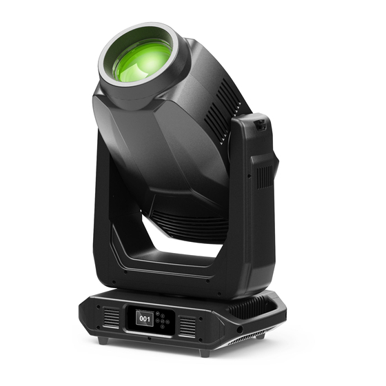
DESCRIPTION:COMPONENTS Luminaire Overview The following illustration shows the external luminaire components and controls. - Page 22 VARI LITE VLZ SPOT Luminaire User’s Manual Notes...
-
Page 23: Chapter 2. Installation
CHAPTER 2. Installation This chapter contains instructions for installation of the luminaire. It includes connecting power and data, along with instructions for powering up the luminaire for the first time and addressing it within your system. Special Warnings Power and Data Cabling Requirements Installation Procedures Powering Up Addressing... -
Page 24: Special Warnings
VARI LITE VLZ SPOT Luminaire User’s Manual Special Warnings Exceptional Safety Information for the VLZ SPOT Luminaire The light intensity and power density of the VLZ SPOT Luminaire exceeds that of other fixtures typically used in this application. The warnings and cautions that follow are critically important to the safe operation of this fixture. -
Page 25: Power And Data Cabling Requirement
INSTALLATION : POWER AND DATA CABLING REQUIREMENTS Power and Data Cabling Requirements Power The luminaire requires standard AC power distribution from AC100-240V~, 50/60Hz. Current required depends on the AC supply voltage and product model. Note: The mating Neutrik PowerCon connector is supplied, however, you will need to purchase or construct a cable appropriate for your application. - Page 26 VARI LITE VLZ SPOT Luminaire User’s Manual For single-phase power at 240 volts RMS: Connection AC Neutral AC Line Ground(Earth) For three-phase power at 208 volts RMS: Connection Phase 1 Phase 2 Ground (Earth) WARNING: It is not recommended to power any VARI LITE luminaire from a dimmer - even in 'NONDIM' mode.
-
Page 27: Dmx Termination Connector
To construct your own connector, you will need the following components: 5-pin, male XLR connector. Two 1/4W 5% 120 ohm resistors. Note: A DMX termination connector assembly is available as an accessory from Philips Vari-Lite. See “Replacement Items/Accessories” on page 6. -
Page 28: Installation Procedures
VARI LITE VLZ SPOT Luminaire User’s Manual Installation Procedures Hanging the Luminaire The VLZ SPOT Luminaire can be hung horizontally or vertically from any structure designed to work with the type of load created by this moving luminaire. Two mounting truss hooks or other mounting hardware are required. - Page 29 INSTALLATION : POWER AND DATA CABLING REQUIREMENTS Figure 2-3: Installing Brackets on Luminaire Enclosure...
-
Page 30: Floor Mounting The Luminaire
VARI LITE VLZ SPOT Luminaire User’s Manual Floor Mounting the Luminaire All luminaires included in this manual are designed to sit directly on its base in a floor installation application. When used in this type of application, be sure to leave enough space around the luminaire to allow proper, uninterrupted airflow for cooling and movement. -
Page 31: Powering Up
INSTALLATION : POWER AND DATA CABLING REQUIREMENTS Powering Up Power Up and Configuration Procedure The internal color, gobo, and beam mechanisms will also move through a full range of motion. After calibration, the luminaire head will either stop at its "home" position (which positions the pan axis at mid-rotation and the head parallel to the yoke with the lens pointing away from the luminaire upper enclosure) or move to its current DMX-defined position if DMX data is present. -
Page 32: Addressing
VARI LITE VLZ SPOT Luminaire User’s Manual Addressing Program Starting Address The address setting for DMX console controlled systems is entered using the Menu Display (refer to “Menu Operation” on page 45). The luminaire retains the DMX address even if power is removed. -
Page 33: Chapter 3. Operation
CHAPTER 3. Operation This chapter contains instructions for operating the luminaire using DMX control and for updating the internal software. VLZ SPOT DMX Channels VLZ SPOT DMX Mapping VLZ SPOT Luminaire Timing Updating Software... -
Page 34: Vlz Spot Dmx Channels
VARI LITE VLZ SPOT Luminaire User’s Manual VLZ SPOT DMX Channels VLZ SPOT Channel Mapping These tables assume a DMX start address of 1. When a different starting address is used, this address becomes channel 1 function and other functions follow in sequence. - Page 35 OPERATION : VLZ SPOT DMX MAPPING 0 - 2 Idle 3 - 5 Linear Dimming Curve 6 - 10 Square Law Dimming Curve 11 - 15 TV Dimming Curve 16 - 20 Architectural Dimming Curve 51 - 55 Edge Track ON 56 - 60 Edge Track OFF Cyan...
- Page 36 VARI LITE VLZ SPOT Luminaire User’s Manual Color Wheel Used as a control channel for different 0 - 255 movement options of Color Control Wheel 1. 0 - 5 Linear Movement using shortest (quickest) path. 6 - 10 Linear Movement using normal (longest) path.
- Page 37 OPERATION : VLZ SPOT DMX MAPPING 11 - 15 Gobo 2 (Wavy Triangle) Index 16 - 20 Gobo 3 (Lattice) Index 21 - 25 Gobo 4 (Swirl) Index 26 - 30 Gobo 5 (Radial Breakup) Index 31 - 35 Gobo 6 (Neurons) Index 36 - 40 Gobo 7 (Grid) Index 41 - 45...
- Page 38 VARI LITE VLZ SPOT Luminaire User’s Manual 6 - 10 Gobo Selection using normal (longest) path. 11 - 20 Reserved Values 21 - 50 Wheel Spin Forward (Fast to Slow) 51 - 60 Wheel Spin STOP 61 - 90 Wheel Spin Reverse (Slow to Fast)
- Page 39 OPERATION : VLZ SPOT DMX MAPPING Gobo 7 (On the Rocks) Rotate with Mega 116 - 120 Stepping 121 - 255 Reserved Values Gobo 16-bit control of index and rotation of gobo Rot/Index 0 - 65535 32767 wheel 1. High Byte 0~126 Rotate Fast to Slow <<<...
- Page 40 VARI LITE VLZ SPOT Luminaire User’s Manual Prism Index/Rot 0 - 65535 32767 16-bit control of prism rotation and index. High Byte 0~126 Rotate Fast to Slow <<< 127~128 Rotation STOP 129- 255 Rotate Slow to Fast >>> Low Byte...
- Page 41 OPERATION : VLZ SPOT DMX MAPPING - See Timing Channel Chart in User Manual Beam Adjustment of fixture timing to control beam Timing 0 - 255 shaping mechanisms. - See Timing Channel Chart in User Manual Adjustment of fixture timing to control gobo Gobo Timing 0 - 255 mechanisms.
- Page 42 VARI LITE VLZ SPOT Luminaire User’s Manual minutes will behave as a toggle. Standard Mode - Fixture operates at maximum 81 - 85 output (Default) Studio Mode - Reduced output with lower fan 86 - 90 settings 91 - 255...
-
Page 43: Vlz Spot Control Channel Functions
OPERATION : VLZ SPOT DMX MAPPING VLZ SPOT Control Channel Functions Control channel functions allow special actions such as reset and partial recalibration. These must be executed with zero time transition or with timing disabled. Discrete values must be used; not manual controls such as faders or encoders (see chart below for values). - Page 44 VARI LITE VLZ SPOT Luminaire User’s Manual Step 2. Set control channel value for desired action (for example, 36 for ReCal). Hold value for 3 seconds. Step 3. Set control channel value to zero. (This must occur without any scaling values. Action will be voided if other values are detected between action value and zero.)
-
Page 45: Vlz Spot Dmx Mapping
OPERATION : VLZ SPOT DMX MAPPING VLZ SPOT DMX Mapping VLZ SPOT Color Control The luminaire’s color system is composed of a CMY color mixing mechanism and two fixed color wheels. The follow sections describe these components. Color Mixing The color mixing mechanism is made up of four graduated color disks: cyan, magenta, yellow and CTO (color temperature orange). -
Page 46: Fixed Color Wheel 2
VARI LITE VLZ SPOT Luminaire User’s Manual Table 3-4: VLZ SPOT Fixed Color Wheel 1 Standard Configuration Chart Position Color Filter Part Number 6.03.05.03.2519 Yellow 6.03.05.03.2520 Kelly Green 6.03.05.03.2521 Magenta 6.03.05.03.2522 Amber 6.03.05.03.2523 Congo Blue 6.03.05.03.2524 Fixed Color Wheel 2 Fixed color wheel 2, like fixed color wheel 1, offers timed changes, half and full frame positions, and various spin rates in either direction. -
Page 47: Fixed Color Wheels Dmx Map
OPERATION : VLZ SPOT DMX MAPPING Fixed Color Wheels DMX Map Table 3-6: VLZ SPOT DMX Map for Fixed Color Wheels 1 and 2 Range Parameter Defaults Description Channel Color 0 – 255 8-bit linear control of Color Wheel 1. See Channel 21 for options. Wheel 1 0 –... -
Page 48: Vlz Spot Gobo/Effects Control
VARI LITE VLZ SPOT Luminaire User’s Manual VLZ SPOT Gobo/Effects Control Overview of Gobos used in VLZ SPOT Luminaire Due to the immense energy and light produced by VLZ SPOT luminaires, Vari-Lite recommends to users and owners of this fixture follow the guidelines outlined below when loading gobos in any of the two rotating gobo wheels. -
Page 49: Gobo Wheels 1And 2
OPERATION : VLZ SPOT DMX MAPPING Gobo Wheels 1 and 2 These wheels have five positions, one being open. Figure 3-3 illustrates the standard gobo configurations: Figure 3-3: Gobo Wheels 1and 2 Positions For each wheel and their associated standard gobo, refer to: “VLZ SPOT Gobo Wheel 1 Standard Configuration Chart”... - Page 50 VARI LITE VLZ SPOT Luminaire User’s Manual Table 3-8: VLZ SPOT Gobo Wheel 1 Standard Configuration Chart Position Gobo Style Part Number No Gobo Open VL-GA258 6.03.03.01.0608 GA204 6.03.03.01.0621 VL-GA255 6.03.03.01.0610 VL-GA206 6.03.03.01.0611 GA026 6.03.03.01.0612 VL-GA274 6.03.03.01.0613 VL-GA263 6.03.03.01.0614 Note: Raw artwork shown for gobos and gags is for reference only.
-
Page 51: Index And Rotation
OPERATION : VLZ SPOT DMX MAPPING Index and Rotation The gobo wheels operate in two modes: INDEX Mode and ROTATE Mode. The corresponding values are given in the DMX Map Tables below. Gobos will also behave as follows: Gobo wheels will only stop at whole images. Timed moves are only available using the Gobo Time channel. -
Page 52: Vari Lite Vlz Spot Luminaire User's Manual
VARI LITE VLZ SPOT Luminaire User’s Manual Table 3-11: VLZ SPOT DMX Map for Gobo Wheel 1 and 2 31 - 35 Gobo 6 (HONEYCOMB) Index 36 - 40 Gobo 7 (On the Rocks) Index 41 - 45 Open - No Gobo... -
Page 53: Vlz Spot Luminaire Timing
OPERATION : VLZ SPOT DMX MAPPING VLZ SPOT Luminaire Timing VLZ SPOT Timing Channel Information Timing channel control improves the timed moves of certain groups of parameters. We provide up to four timing channels - Focus (pan and tilt),Optics Time (lens),Color Time (color parameters), Beam Time (beam parameters), and Gobo Time (gobo wheel operation). - Page 54 VARI LITE VLZ SPOT Luminaire User’s Manual Note: The particular storing syntax for your console, as well as instructions on how to write part cues, can be found in the operation manual for that console. To use these channels, you must: Step 1.
-
Page 55: Updating Software
OPERATION : VLZ SPOT DMX MAPPING Updating Software Transferring Software From Luminaire to Luminaire It is possible to transfer specific software versions between luminaires. As in the case of installing new software versions, multiple luminaires can be programmed at the same time if they are data linked together (refer to “Connecting Data and Power”... - Page 56 VARI LITE VLZ SPOT Luminaire User’s Manual A DMX termination connector is used in this process. Refer to page 11 for more information regarding the construction of this connector. Figure 3-5: Software Transfer Setup Transfer Procedure This procedure is used to transfer software versions between luminaires.
- Page 57 OPERATION : VLZ SPOT DMX MAPPING Notes...
-
Page 58: Chapter 4. Menu System
CHAPTER 4. Menu System This chapter contains instructions for operating the luminaire using the Menu Display feature. Menu Operation Menu Functions Self-Tests... -
Page 59: Menu Operation
VARI LITE VLZ SPOT Luminaire User’s Manual Menu Operation What Is the Menu System? The menu system is a programmable set of commands used to configure, address, operate, and test the luminaire. The menu system is controlled at the Menu Display available at the enclosure input panel. -
Page 60: Default State
MENU SYSTEM : MENU OPERATION Default State The menu display’s default state during normal operation is to display the DMX address. After 40 seconds of inactivity at the display, it will change to the default state. After longer periods of inactivity, the menu display will switch to its off state. The default state for this feature is 30 seconds, however, different time lengths can also be programmed. -
Page 61: Menu Functions
VARI LITE VLZ SPOT Luminaire User’s Manual Menu Functions VLZ SPOT Menu System Function Chart Table 4-1: VLZ SPOT Menu System Chart 001~512 (Default 001) Address Standard (Default) Power Level Studio 900~25000Hz Refresh Freq (Default 1200Hz) 2.0~2.8 Gamma (Default 2.0) - Page 62 MENU SYSTEM : MENU OPERATION Table 4-1: VLZ SPOT Menu System Chart Status (No Errors... or displays a list of errors) Recalibrate (Fixture) Are you sure? Reboot Fixture Are you sure? Version VXXX MM/DD/YY HH:MM Fixture Hours XXXXXX h Crossload Unplug DMX From Console? (Software) Tilt...
- Page 63 VARI LITE VLZ SPOT Luminaire User’s Manual Table 4-1: VLZ SPOT Menu System Chart Intensity Value 0 - 255 (Default 0) Manual Intensity fine Value 0 - 255 (Default 0) Control …… …… (Default 0) All Test (Run 'ALL TEST' )
-
Page 64: Menu Function Definitions
MENU SYSTEM : MENU OPERATION Menu Function Definitions For easy reference, each possible menu item is listed alphabetically in the first column by its display abbreviation. The second column follows with a definition of the abbreviation and then a third column provides an explanation of its purpose and function. -
Page 65: Self-Tests
VARI LITE VLZ SPOT Luminaire User’s Manual Self-Tests Running Parameter Tests The luminaire is capable of running self-tests by using the Testmenu functions. When running tests on multiple luminaires, a DMX termination connector is required at the last luminaire in the link. Refer to “Connecting Data and Power”... - Page 66 MENU SYSTEM : MENU OPERATION Notes...
-
Page 67: Appendix A. Luminaire Care And Routine Maintenance
APPENDIX A Luminaire Care and Routine Maintenance This appendix provides instructions for troubleshooting and routine maintenance which may be necessary during the life of the luminaire. Equipment Handling Troubleshooting Routine Maintenance WARNING: All maintenance procedures are to be performed with power removed from the luminaire. -
Page 68: Equipment Handling
VARI LITE VLZ SPOT Luminaire User’s Manual Equipment Handling Below are some basic tips and information on handling luminaires and their associated components. Locations/Use VARI LITE luminaires are designed for dry locations only. Exposure to rain or moisture (including, but not limited to, fog machines, misters, etc.,) may damage luminaire. -
Page 69: Solid State Electronics
TROUBLESHOOTING AND MAINTENANCE Solid State Electronics Electrostatic Discharge (ESD) Electrostatic discharge (ESD) presents a significant danger to solid state electronic components (semiconductor devices and PC board assemblies). Static electricity can build on a variety of common objects (including people) simply by handling or moving. ESD rarely results in immediate failure of a component, but shows up later as an intermittent problem or severely reduces the life of the component. -
Page 70: Troubleshooting
VARI LITE VLZ SPOT Luminaire User’s Manual Troubleshooting Error Messages If a problem occurs during luminaire calibration, at the end of the calibration sequence the Menu Display will cycle through any applicable error message(s) until the end of the list is reached. -
Page 71: Troubleshooting Guide
TROUBLESHOOTING AND MAINTENANCE Troubleshooting Guide If a problem is suspected, first try recalibrating the luminaire to prompt an error message. The chart below provides possible causes and remedies for various error messages and/or symptoms. -
Page 72: Routine Maintenance
VARI LITE VLZ SPOT Luminaire User’s Manual Routine Maintenance LED Replacement WARNING: Ensure that power is removed from luminaire when installing LED. CAUTION: Wear cotton gloves or other covering while installing LED. Touching LED glass with bare fingers will leave oil and may cause the LED to explode or reduce LED life. -
Page 73: Gobo Replacement - Gobo Wheels
TROUBLESHOOTING AND MAINTENANCE Gobo Replacement - Gobo Wheels Tools: Crossed Slot screwdriver Overview of Gobos used in VLZ SPOT Luminaire Due to the immense energy and light produced by VLZ SPOT luminaires, Vari-Lite recommends to users and owners of this fixture follow the guidelines outlined below when loading gobos in any of the two rotating gobo wheels. - Page 74 VARI LITE VLZ SPOT Luminaire User’s Manual Figure A-2: Head Covers – Removal Step 3. If removing gobos via bottom of head assembly, undo fan tray assembly with thumb screw to access. Step 4. Rotate desired gobo wheel until required gobo position is accessible.
- Page 75 MENU SYSTEM : MENU OPERATION Step 5. Remove current gobo by carefully pressing on edges of gobo carrier with fingers, pressing gobo toward front end of luminaire (toward lens), and out of wheel. Do not touch glass with bare fingers. CAUTION: Press on gobo carrier only.
-
Page 76: Cleaning Optics, Filters And Gobos
VARI LITE VLZ SPOT Luminaire User’s Manual Cleaning Optics, Filters and Gobos WARNING: Remove power from luminaire before performing maintenance. WARNING: Acetone is a harsh cleaning agent and solvent. Acetone is very flammable. Please handle acetone according to manufacturer’s safety instructions and precautions. -
Page 77: Followspot Handle Accessory Installation (Optional)
TROUBLESHOOTING AND MAINTENANCE Followspot Handle Accessory Installation (Optional) The VLZ SPOT Luminaire can be hung horizontally or vertically from any structure designed to work with the type of load created by this moving luminaire. Two mounting truss hooks or other mounting hardware are required. Many compatible truss hooks are available from different manufacturers for your particular needs. - Page 78 VARI LITE VLZ SPOT Luminaire User’s Manual Figure A-6: Installing Brackets on Luminaire Enclosure...
- Page 79 TROUBLESHOOTING AND MAINTENANCE Notes...
-
Page 80: Appendix B. Technical Specifications
APPENDIX B Technical Specifications VLZ SPOT Luminaire PROGRAMMABLE FUNCTIONS Color System Six color control wheels total. A three filter CMY cross fading system, two fixed color wheels, and a variable CTO color temperature correction wheel. Zoom Optics Covering a range from 7° to 50°. Beam Size Control A mechanical iris provides continuous beam size control for rapid and smooth timed beam angle changes. - Page 81 VARI LITE VLZ SPOT Luminaire User’s Manual OPTICAL Source Color Temperature 7400K Output Standard Mode:23925 lumens Studio Mode:15316lumens Gobo Metal gobos are not acceptable. OPERATIONAL Power Requirements Standard AC power distribution from 100-240 VAC, 50/60 Hz. The unit requires up to 15 A depending on the AC supply voltage.
- Page 82 TROUBLESHOOTING AND MAINTENANCE Dimensions...
- Page 84 Philips Vari-Lite 10911 Petal Street Dallas, Texas 75238 USA 1-877-VARI-LITE . 1-214-647-7880 http://www.philips.com/entertainmentlighting ©2013 Philips Vari-Lite, a Philips group company. All Rights Reserved.
Need help?
Do you have a question about the VARI LITE VLZ SPOT Luminaire and is the answer not in the manual?
Questions and answers