Table of Contents
Advertisement
Advertisement
Table of Contents

Subscribe to Our Youtube Channel
Related Manuals for Tomos REVIVAL


Summary of Contents for Tomos REVIVAL
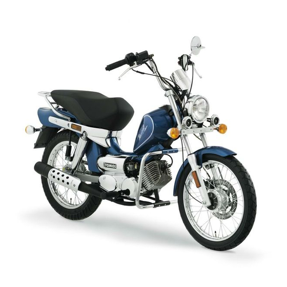
- Page 1 Revival USER'S MANUAL BEDIENUNGSANLEITUNG HAN DLEIDING MANUEL D'UTILISATION...
-
Page 2: Table Of Contents
CONTENTS Warnings Cleaning Riding Safety Tips Fuel System Cleaning Tech nica 1 Specifications Exhaust System Cleaning Technical Description Vehicle Cleaning Vehicle Operation Checks and Adjustments Fuel Engine Oil Level Check Engine Starting Bowden Adjustment Riding Transmission Chain Adjustment Engine Running-Jn Bolt and Nut Tightness Luggage Space Maintenance Schedule... -
Page 3: Warnings
WARNINGS No mo n of the vehicle, ing- ff of any parts or installing of non-miginal spare parts is permitted. The vehicle owner is s · Prior to operating the vehicle, ca fully read thi s User's Manual in cally warned that any modification to the exhaust system can only order to get... -
Page 4: Tech Nica 1 Specifications
(rear mirror) and try anticipate events. Model REVIVAL Standard, Full optional The braking method affects the loading on each wheel: the front brake increases the effect of braking, whereas braking with the... - Page 5 Suspension light Front shock absorber travel 7omm Direction indicator signal 12V1.5W Rear shock absorber travel Oil level indicator light 12V 1 . 5W beam headlamp indicator light 12V1.5W Wheels Front tire dimensions 2 1/2-17" Main beam headlamp i ndicator light 12V I.SW Rear tire dimensions Battery (FULL OPTIONAL) 3/4-16"...
-
Page 6: Technical Description
TECHNICAL DESCRIPTION Rear brake pedal 20. Oil reservoir Direction indicator switch Fuel tank Horn s��tch filter Main beam/101-1 beam switch 23.Chokelever Ignition switch (FULL OPTIONAL) carburetor fuse (FULL OPTIONAL) Battery and fuel filling vent Speedometer fuel shut·off cock Luggage carrier Handlebar lock Brake fluid reservoir (FULL OPTIONAL) - Page 7 2, 3, 4 10, 11 Fig. 3...
- Page 8 Fig. Fig. 5...
-
Page 9: Vehicle Operation
VEHICLE OPERATION Fuel r+ two-stroke engine oil, in the rati o 1:50 (2%). The moped is equipped oil pump that xes, in endent of the eng on s eed, oil to the fuel as speciAed two e rotat stroke engines (2%). CAUTION! Prior starting the engine... - Page 10 Open fuel shut-off cock (Fig.7}. Note: A· l supply shut-off. fuel supply reserve • If the engine is cold. press the ch lever (B, Fig.8). tvith the throttle full y closed, press the rear brake pedal and press (FULL start electric lever (11,...
-
Page 11: Riding
Riding The speed is controlled by the throttle lever (12, Fig. 1). Engaging the first or second gear is done by opening or closing the throttle. Avoid switching too frequentl.Y between first and second gears. In such situa tions-;-yoa should instead reduce the throttle opening and keep the vehicle in first gear. -
Page 12: Maintenance
Caution: system) and checking of safety-related riding components (tire pres· When operating the engine in conditions of high ambient tempera sure, operation of lights and brakes, tightness of bolts and nuts). The tures, the temperature in the luggage space rises considerably. maintenance schedule specifies maintenance operations and their Therefore, do not store temperature-sensitive objects in the lug... -
Page 13: Changing And Checking Brake Pads
Fig. Changing and Checking Brake Pads (Disc Brake Model) Brake pads are checked visually. As soon as the brake pad wear reach es the grooves (A, Fig. 10), the pads should be replaced by an author ized service agent. Check the brakes for any grease smears. In the case you notice such smears, take the vehicle immediately to an authorized service agent examination and repair. -
Page 14: Changing And Checking Brake Fluid
is blown, turn the ignition switch (5, Fig. 1) position. to the OFF Changing and Checking Brake Fluid (Disc Brake Model) Replace the fuse a new one of the correct specifications. Return wi t h the ignition switch to the position and check operation. -
Page 15: Exhaust System Cleaning
Exhaust System Cleaning (Fig. 13) The build up of soot in the exhaust system obstructs the free passage of exhaust gas and thereby reduces engine power. Unscrew the bolt at the exhaust pipe's rear end, pull the silencer out and clean it free of soot exhaust pipe inlet open... -
Page 16: Vehicle Cleaning
CHECKS AND ADJUSTMENTS Engine Oil Level Check Regularly oil level in the reservoir under the seat. Top of as check the required. Should the warning light fail to extinguish after starting the engine, this means oil level is low and immediate topping required. -
Page 17: Transmission Chain Adjustment
Fig. 16 Transmission Chain Adjustment The chain tension should be adjusted so that the chain yields 10 mm up or down under pressure (Fig. 16). Adjust the chain tension by spin ning the chain tensioners on rear wheel axis (B, Fig. i6). After the adjustment, retighten the wheel axis nuts that were partly released Fig. -
Page 18: Bolt And Nut Tightness
iomm iomm Fig. Bolt and Nut Tightness Periodically check and retighten as necessary the bolts and nuts components the main vehicle (wheels, handlebar, rear shock xis, engine to bolts, gearbox oil drain absorbers, rear fork a frame plug). -
Page 19: Maintenance Schedule
MAINTENANCE SCHEDULE 20 00 interval (miles) 1000 2000 3000 interval (miles) 1000 3000 interval (months) interval (months) Oil lubrication Checks and adjustments • • • • • • • • GearbOx oil change 12. Gearbox oil level • • • •... -
Page 20: Battery Installation
BATTERY INSTALLATION part of the tank housi Open the luggage space on th e right Release the two bolts of the Fig. lift-side part the tank. sideways on ribs. wi t h Place the battery shoes fac ing upwards, pull the installed rubber band (A, Fig. 18) over the bat... -
Page 21: Troubleshooting
TROUBLESHOOTING Wet spark or electrodes in a short circuit: · Spark plug electrodes frequently in a short circuit: · Fuel System Troubles clean soot build-up from the cylinder head and piston head. Possible causes of the engine failing to start or stopping during a ride - Spark plug electrodes are worn out: include: adjust the electrode clearance according to the specifications. -
Page 22: Gearbox Troubles
· Wheel brakes do no disengage completely: jerks: - After engaging the second gear, the clutch the Bowdens b chain is too loose adjust the chain's oil and • tension; Improper setting of advance angle: - Low gearbox oil level - top •... -
Page 23: Electrical System Diagram Full Optional 2
Electrical System Diagram FULL OPTIONAL direction indicator lamp Left Ignition switch Right directi o n indicator lamp Starter Horn Starter cranking relay Headlamp Battery Oil switch Side lamp Stop la Ignition electronics Instrument illumination Generator Direction indicator signal lamp Relay Main headlamp indicator lamp regulator... -
Page 24: Electrical System Diagram Standard
Electrical System Diagram STANDARD Left direction indicator lamp Ignition electronics 2. Right direction indicator lamp 20. Generator 3. Horn 21. Relay 4. Headlamp regulator Side lamp Stop lamp Instrument illumination Direction indicator signal lamp Main beam headlamp indicator lamp Low beam headlamp indicator lamp 11. - Page 25 FULL OPTIONAL...
- Page 26 STANDARD 1 2 .
Need help?
Do you have a question about the REVIVAL and is the answer not in the manual?
Questions and answers