Table of Contents
Advertisement
Quick Links
Operator's Manual
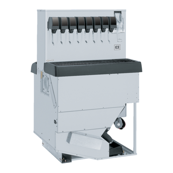
THE PROFILEtICE/DRINK DISPENSER
Model: PR150 BC
IMPORTANT:
TO THE INSTALLER.
It is the responsibility of
the Installer to ensure that
the water supply to the
dispensing equipment is
provided with protection
against backflow by an air
gap as defined in
ANSI/ASME A112.1.2-1979;
or an approved vacuum
breaker or other such
method as proved effective
by test.
Water pipe connections
and fixtures directly
connected to a potable
water supply shall be
sized, installed, and
maintained according to
Federal, State, and Local
Codes.
Part No. 620918702
October 5, 2001
Revision Date: April 22, 2009
Revision: E
THIS DOCUMENT CONTAINS IMPORTANT INFORMATION
This Manual must be read and understood before installing or operating this equipment
©
IMI CORNELIUS INC; 2001--2009
IMI CORNELIUS INC
www.cornelius.com
Telephone (800) 238- -3600
PRINTED IN U.S.A
Advertisement
Table of Contents

Subscribe to Our Youtube Channel
Related Manuals for Cornelius PR150 BC


Summary of Contents for Cornelius PR150 BC
- Page 1 IMI CORNELIUS INC www.cornelius.com Telephone (800) 238- -3600 Operator’s Manual THE PROFILEtICE/DRINK DISPENSER Model: PR150 BC IMPORTANT: TO THE INSTALLER. It is the responsibility of the Installer to ensure that the water supply to the dispensing equipment is provided with protection...
-
Page 2: Table Of Contents
TABLE OF CONTENTS SAFETY INFORMATION ........... . RECOGNIZE SAFETY INFORMATION . - Page 3 TABLE OF CONTENTS FIGURE 1. MOUNTING TEMPLATE ........FIGURE 2.
-
Page 4: Safety Information
SAFETY INFORMATION Recognize Safety Information This is the safety-alert symbol. When you see this symbol on our machine or in this manual, be alert to the potentially of personal injury. Follow recommended precautions and safe operating practices. Understand Signal Words DANGER A signal word - DANGER, WARNING, OR CAUTION is used with the safety-alert symbol. - Page 5 THIS PAGE LEFT BLANK INTENTIONALLY 620918702...
-
Page 6: Safety Precautions
Designed to be manually filled with ice, this dispenser will dispense ice cubes (up to 1--1/4 inches in size), cube- lets, and hard chipped or cracked ice. SPECIFICATIONS Model: PR150 BC Ice Drink Dispenser (Eight--Flavor) Dimensions 31--7/8 inches wide X 27--7/8 inches Deep X 21--1/4 inches High with 29 inches Depth Below Countertop Electrical 120 VAC/1 Phase/60 Hz/5.2 Amps Total Current Draw... - Page 7 THIS PAGE LEFT BLANK INTENTIONALLY 620918702...
-
Page 8: Installation Instructions
INSTALLATION INSTRUCTIONS COUNTER HEIGHT DISPENSER AVAILABLE SPACE USE KIT NO. (INCHES) DEPTH BELOW DISPENSER (INCHES (INCHES) CONSULT FACTORY CONSULT FACTORY 620517502 629087406 629087406 629087406 34--1/2 5--1/2 629087412 620517502 629087412 629087412 COUNTERTOP INSTALLATION IMPORTANT: It is the responsibility of the installer to ensure that the drains from the dispensing equipment is installed and maintained according to Federal, State, and local laws. -
Page 9: Figure 1. Mounting Template
FOOT PRINT OF UNIT ON COUNTERTOP 29 - - 5/8 COUNTER CUTOUT UNIT DROP IN 27- - 3/16 25- - 3/4 FRONT OF COUNTERTOP 31- - 7/8 THE ABOVE FIGURE SHOWS THE REQUIRED CUTOUT FOR PLACING THE ICE DISPENSER INTO A COUNTERTOP. THE DASHED LINE IS THE ACTUAL CUTOUT DIMENSIONS WHILE THE SOLID LINE SHOWS THE AMOUNT OF OVERHANG FOR THE DISPENSER. - Page 10 620918702...
- Page 11 THIS PAGE LEFT BLANK INTENTIONALLY 620918702...
-
Page 12: Maintenance
MAINTENANCE The following dispenser maintenance should be performed at the intervals indicated. DAILY (or as required) Remove foreign material from the vending area drip tray to prevent drain blockage. Clean vending area. Check for proper water drainage from the vending area drip tray. MONTHLY Clean and sanitize the hopper interior and the beverage system if applicable (see CLEANING INSTRUCTIONS) -
Page 13: Adjusting Water-To-Syrup "Ratio" (Brix) Of Dispensed
1. Remove cover from the dispensing valve by lifting the front cover up 1/4 inch and pulling forward. 2. Install syrup diversion tube assembly on the dispensing valve by pushing rubber end of the syrup diversion tube onto the syrup outlet of the inner nozzle. 3. -
Page 14: Start--Up And Operating Instructions
2. Install syrup diversion tube assembly on the dispensing valve by pushing the rubber end of the syrup diver- sion tube onto the syrup outlet of the inner nozzle. Notice: Refer to syrup manufacturer’s recommendations on syrup package for water-to-syrup ratio. 3. -
Page 15: Cleaning And Sanitizing Instructions
FIGURE 4. AUGER ASSEMBLY CLEANING AND SANITIZING INSTRUCTIONS WARNING: Disconnect electrical power to the dispenser before cleaning. Do not use metal scrapers, sharp objects, or abrasives on the ice storage hopper, top cover, and the agitator disk as damage may result. Do not use solvents or other cleaning agents as they may attack the plastic material. -
Page 16: Figure 5. Drip Tray And Rear Cover Removal
Wash cup rest with soap solution and rinse with potable water. Install cup rest in drip tray. Clean all exterior surfaces of the dispenser with soap solution and rinse with potable water. 2. CLEANING INTERIOR SURFACES CAUTION: When pouring liquid into the hopper, do not exceed the rate of 1/2- -gallon per minute. -
Page 17: Cleaning Dispensing Valves
Reassemble the agitator assembly and disc into the hopper. Make certain the retaining screw is tight. Using a mechanical spray bottle filled with sanitizing solution, spray the entire interior of the hopper and the agitator assembly. Go to the lower auger drive area and also spray with sanitizing solution. Allow to air dry. -
Page 18: Sanitize B-I-B Systems
11. For post-mix valves, remove the nozzle and syrup diffuser and clean them in a mild soap solution. Rinse with clean water and reassemble the nozzle and syrup diffuser on the valve. 12. For pre-mix valves, disconnect all product tubes from the tank of sanitizing solution and then open the valves to allow the pressure to be relieved. - Page 19 620918702...
- Page 20 FIGURE 8. LADDER DIAGRAM 620918702...
- Page 21 THIS PAGE LEFT BLANK INTENTIONALLY 620918702...
-
Page 22: Troubleshooting
TROUBLESHOOTING IMPORTANT: Only qualified Personnel should service internal components or electrical wiring. WARNING: If repairs are to be made to a syrup system, disconnect syrup supply from the applicable syrup system, then relieve the system pressure before proceeding. If repairs are to be made to the CO system, stop dispensing, shut off the CO supply, then relieve the... -
Page 23: Agitator Turns, Auger Does Not Turn (Cont'd)
Trouble Probable Cause Remedy AGITATOR TURNS, AUGER Inoperative rectifier. Replace rectifier. DOES NOT TURN (CONT’D) Ice jam. Clear ice jam. Inoperative timer board. Replace timer board. AUGER TURNS, AGITATOR Inoperative agitator motor. Replace agitator motor. DOES NOT. Inoperative motor capacitor. Replace motor capacitor. -
Page 24: Illustrated Parts List
ILLUSTRATED PARTS LIST 117127 41 42 1 2 3 4 128 620918702... - Page 25 69 20 18 19 97 102 123 149 157 26 32 160 161 8 14 45 620918702...
- Page 26 620918702...
-
Page 27: Pr150Bc Assembly
PR150BC ASSEMBLY Item Part No. Name 1919 Mounting Block Ass’y, UF-1 1950 Cover, Valve, Back 1951 Cover, Valve, Front 1966 Dispensing Valve 15087 Retainer, Agitatotr 27107 Retainer, Ice Lever 29303R Plate, Motor Mount 30794 Heater, Agitator Motor, 115v 32826 Heater, Agitator Motor, 230v 02070 Kit Switch, includes switch, boot, and spacer 30995... -
Page 28: Pr150Bc Assembly (Cont'd)
Part No. Name 90432 Label, Warning, Disconnect 90580 Label, Identification Data 90629 Label, Clean Hopper 91486 Medallion, Cornelius Logo 91956 Label, Warning Chiller Disconnect 92067 Label, Operation, Agitation Timer 92305 Label, Notice Transformer 31525003 O-Ring, .239 I.D. By .070 CS 31525017 O-Ring, .426 I.D. -
Page 29: Pr150Bc Assembly (Cont'd)
PR150BC ASSEMBLY (CONT’D) Item Part No. Name 620045724 Base, Tower LH 620045727 Base, Tower RH 620045904 Bracket, Dispense Switch 620045958 Bracket Ass’y, Interlock Switch 620046005 Cover, Reservoir 620046017 Cover, Bin Thermostat 620048102 Panel, Tower, Back 70076 Hex Nut, Keps, No. 8-32 70188 Screw, Knurled Hd, No. -
Page 30: Pr150Bc Assembly (Cont'd)
PR150BC ASSEMBLY (CONT’D) Item Part No. Name 620704604 Fitting, 3/8 By 1/2 MPT 620708524 Cup Rest 620705201 Pushon Nut, 3/16 620705401 Insert Nut, 1/2-13 620705501 Retainer, Ice Chute Holddown 620708202 Plug 620708908 Tube, Bin Stat 620709301 Lever, Ice 620709601 Clip, Pushon 620709604 Clip, Back Lid, Left-Hand 620707605... - Page 31 WARRANTY IMI Cornelius Inc. Products Company warrant that all equipment and parts are free from defects in material and workmanship under normal use and service. For a copy of the warranty applicable to your Cornelius product, in your country, please write, fax or telephone the IMI Cornelius office nearest you. Please provide the equipment model number and the date of purchase.
- Page 32 IMI CORNELIUS INC. www.cornelius.com (800) 238-3600...
Need help?
Do you have a question about the PR150 BC and is the answer not in the manual?
Questions and answers