
Related Manuals for M/A-Com M7250


Summary of Contents for M/A-Com M7250
- Page 1 Installation Manual MM-007024-001 Sep-05 M7200 Series Mobile Radio Trunk-Mount Full-Duplex Mobile Radio with Control Head for OpenSky Radio Networks...
- Page 2 This manual is published by M/A-COM, Inc. without any warranty. Improvements and changes to this manual necessitated by typographical errors, inaccuracies of current information, or improvements to programs and/or equipment, may be made by M/A-COM, Inc., at any time and without notice. Such changes will be incorporated into new editions of this manual.
-
Page 3: Table Of Contents
TRANSCEIVER........................9 REGULATORY ......................... 10 INTRODUCTION ........................11 GENERAL DESCRIPTION....................11 RELATED DOCUMENTS....................13 CONTACTING M/A-COM FOR TECHNICAL ASSISTANCE ..........13 UNPACKING AND CHECKING EQUIPMENT................ 14 MATERIALS........................14 MATERIAL INSPECTION ....................17 PLANNING THE INSTALLATION................... 18 GENERAL INFORMATION ....................18 TOOLS REQUIRED ...................... - Page 4 MM-007024-001 (Continued) TABLE OF CONTENTS Page CONTROL HEAD INSTALLATION..................33 GENERAL INFORMATION ....................33 BRACKET INSTALLATION....................34 9.2.1 Standard U-Shaped Bracket .....................34 9.2.2 Mounting Pedestal (Optional)....................34 ATTACH CONTROL HEAD TO BRACKET............... 34 CAN CONNECTIONS ....................... 35 9.4.1 General Information.........................35 9.4.2 Make CAN Termination......................35 9.4.3 Connect Control Head to Radio Via CAN Cable ..............36...
-
Page 5: Safety Information
RF exposure limits. This radio is NOT authorized for general population, NOTE consumer, or any other use. Changes or modifications not expressly approved by M/A-COM, Inc. could void the user's authority to operate the equipment. CAUTION This two-way radio uses electromagnetic energy in the radio frequency (RF) spectrum to provide communications between two or more users over a distance. -
Page 6: Federal Communications Commission Regulations
MM-007024-001 specific operating instructions to users of two-way radios. These instructions are important because they inform users about RF energy exposure and provide simple procedures on how to control it. Please refer to the following websites for more information on what RF energy exposure is and how to control your exposure to assure compliance with established RF exposure limits: http://www.fcc.gov/oet/rfsafety/rf-faqs.html http://www.osha.gov./SLTC/radiofrequencyradiation/index.html... -
Page 7: Mobile Antennas
1.3.2 Approved Accessories The radio has been tested and meets FCC RF guidelines when used with M/A-COM accessories supplied or designated for use with it. Use of other accessories may not ensure compliance with the FCC’s RF exposure guidelines, and may violate FCC regulations. For a list of approved accessories refer to section 4 in this manual (begins on page 14) and/or M/A-COM’s Products and Services Catalog. -
Page 8: Common Hazards
MM-007024-001 COMMON HAZARDS The operator of any mobile radio should be aware of certain hazards common to the operation of vehicular radio transmissions. Possible hazards include but are not limited to: Explosive Atmospheres Just as it is dangerous to fuel a vehicle with its motor running, be sure to turn the radio OFF while fueling the vehicle. -
Page 9: Specifications
MM-007024-001 SPECIFICATIONS GENERAL 2.8 x 8.8 x 9.3 inches (7.1 x 22.4 x 23.6 centimeters) Dimensions, Mobile Radio: (Height x Width x Depth) (Includes bracket but not cables) 2.4 x 7.1 x 2.1 inches (6.10 x 18.03 x 5.33 centimeters) Dimensions, Control Head: 8.0 pounds (3.63 kilograms) Weight, Mobile Radio:... -
Page 10: Regulatory
MM-007024-001 Receiver Sensitivity 700 MHz OTP Mode: -111 dBm minimum, -113 dBm typical for 5% BLER 800 MHz OTP Mode: -111 dBm minimum, -112 dBm typical for 5% BLER 700 MHz P25 Mode (TIA-102 Method): -116 dBm minimum, -121 dBm typical for 5% BLER 800 MHz P25 Mode (TIA-102 Method): -116 dBm minimum, -121 dBm typical for 5% BLER 800 MHz OCF Mode (TIA-603 Method):... -
Page 11: Introduction
This manual only covers the installation of the M7250 model mobile radio. The M7250 model mobile radio is designed to operate in a mobile environment, typically within a motor vehicle. It must be connected to an external transmit/receive antenna such as one mounted to the vehicle’s rooftop or trunk lid. - Page 12 The warranties provided to the buyer under the terms of sale shall be null and void if this product is installed or serviced improperly, and M/A-COM shall have no further obligation to the buyer for CAUTION...
-
Page 13: Related Documents
CONTACTING M/A-COM FOR TECHNICAL ASSISTANCE Should the mobile radio or control head require repair, or if there are questions or concerns about the installation of this equipment, contact M/A-COM’s Technical Assistance Center (TAC) using the following telephone numbers or email address: •... -
Page 14: Unpacking And Checking Equipment
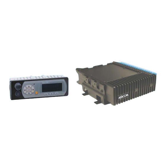
MM-007024-001 UNPACKING AND CHECKING EQUIPMENT MATERIALS An M7250 mobile radio installation consists of two (2) main components: • Trunk-Mount Full-Duplex 700/800 MHz Mobile Radio Unit (MRU), part number RU25011-0001 • CH-103 Control Head, part number MACDOS0003 or CH-103PA Control Head, part number MACDOS0009 Installation Kit MAMV-ZN6X can be used to install the mobile radio, or individual components can be purchased separately as needed. - Page 15 MM-007024-001 Table 4-2: Additional Options and Accessories PART NUMBER DESCRIPTION MACDOS0003 CH-103 Control Head MACDOS0009 CH-103PA Control Head. Includes Siren/PA functionality. MAMV-ZN7P Kit, Accessory; Remote-Mount for Data-Only Radio. Includes (1) Base Bracket 1000003678, (1) 10-foot DC Power Cable, (2) CAN Terminators (1) Fuse Distribution Rail Kit FS23057 and (1) Vehicle Fuse Tap FS24473.
- Page 16 MM-007024-001 Table 4-4: Additional Accessories for CH-103 and CH-103PA Control Heads PART NUMBER DESCRIPTION Kit, Cable; CH-103PA Public Address. Includes (1) 50-Foot Speaker Y- MAMV-CL6R Cable MACDOS0015-NN050, (1) 50-Foot Common Mic Interface Cable MACDOS0014-RN050 and (1) 10-Inch CAN Y-Cable MACDOS0017- BR010.
-
Page 17: Material Inspection
MATERIAL INSPECTION After removal from the carton, examine the radio, control head and other components for broken, damaged, loose or missing parts. If any are noted, contact M/A-COM’s Technical Assistance Center (see page 13) immediately to discuss and arrange the return of the equipment to M/A-COM for replacement. -
Page 18: Planning The Installation
MM-007024-001 PLANNING THE INSTALLATION GENERAL INFORMATION Before starting, plan the installation carefully so it will meet the following requirements: • The installation is safe for the operator and passengers within the vehicle. • The equipment is installed away from the airbag deployment areas. •... - Page 19 MM-007024-001 FRONT VIEW Mobile Radio Unit (MRU) Base Bracket Base Bracket’s Mounting Tabs Mounting Holes (4 places) (Not used; 2 places) REAR VIEW (Shown With Installation Cables NOT Connected) CAN Port Connectors (2 Places) I/O Cable’s DB-44 Connector Antenna Cable’s TNC Connector DC Power Cable’s 3-Pin Connector...
-
Page 20: Locating Components
MM-007024-001 LOCATING COMPONENTS Plan the mounting locations of all components (radio, control head, antenna, and cables) and determine the routes for all wiring and cables. Particularly consider the connection of the control head for planning purposes. • Determine the customer’s preferences, if any, for location of components. Comply with these preferences as long as they are consistent with safety recommendations and guidelines presented in this manual, and other generally accepted professional radio installation practices. -
Page 21: Mounting The Mobile Radio In The Trunk
MM-007024-001 MOUNTING THE MOBILE RADIO IN THE TRUNK This section provides details on mounting the mobile radio in the trunk of the vehicle. See Figure 5-1 and refer to the respective wiring diagram at the end of this manual as necessary. See section 9 (page 33) for control head installation procedures. - Page 22 MM-007024-001 radio installation and removal ease. A minimum distance of two (2) inches is recommended from the front edge of the bracket. The bracket is front/back symmetrical, and left/right symmetrical. As all installations differ, bracket-to-vehicle mounting screws are not included. Steel #10 self-threading screws are recommended.
-
Page 23: Mount The Radio Into The Bracket
MM-007024-001 2. Deburr all newly drilled mounting holes. 3. Set the bracket in place, and install and tighten the mounting screws. 4. Verify the bracket is firmly secured to the mounting surface. A secure mount prevents unreasonable vibration, which could damage the radio and/or cause its cable connections to loosen. MOUNT THE RADIO INTO THE BRACKET The radio should now be mounted into the bracket according to this procedure: 1. -
Page 24: Antenna Installation
MM-007024-001 ANTENNA INSTALLATION ANTENNA MOUNTING LOCATIONS At this time, review all information presented in the SAFETY INFORMATION section of this manual (begins on page 5). A transmitting antenna must be installed in accordance with the guidelines presented in the SAFETY INFORMATION section. Use Table 1-1 as a guide for determining the best possible mounting configuration/location in order to reduce human exposure to radio frequency (RF) WARNING... -
Page 25: Direct Center Or Center-Rear Of Rooftop
RF safety. The antenna cable of M/A-COM approved antennas should never be cut to a shorter length. Instead, excess cable must be tied and stowed. This not only prevents the antenna from radiating above its intended or configured power, but it also allows for future installation considerations. -
Page 26: Install And Connect Gps Antenna
1. Once the mounting location is selected, refer to the antenna manufacturer’s mounting and testing instructions for installation guidance. If necessary, contact M/A-COM’s Technical Assistance Center (see page 13 for contact information). 2. Route the cable from the GPS antenna to the rear of the radio. The cable should be kept out of casual contact from persons within the vehicle. -
Page 27: Radio Dc Power Installation
MM-007024-001 RADIO DC POWER INSTALLATION Refer to the wiring diagrams at the end of this manual. The diagram in section 19 (page 61) includes mobile radio with the CH-103 Control Head. The diagram in section 20 (page 63) is nearly the same with the exception of the three cables designed for use with the CH-103PA Control Heads. -
Page 28: Power Installation Procedure
MM-007024-001 relay could be completely bypassed in this configuration. Similarly, the 2-ampere ATM fuse and fuse holder included in the fuse kit are not needed. Because the “hot wired” configuration renders the function of the Time Delay Relay useless, the Control Head will draw substantial quiescent current continuously from the battery when turned off. - Page 29 MM-007024-001 3. Connect the ring terminal directly to the battery’s positive post (or if present, to a stud on the battery’s main/non-switched power distribution terminal block). 4. Mount the Time-Delay Relay firmly onto a flat surface within the vehicle’s engine compartment and near the battery but away from sources of excessive heat.
-
Page 30: Make Ground Connections At Fuse Block And Time-Delay Relay
MM-007024-001 3/8-Inch Ring Terminal: To Positive (+) Battery Post In-Line ATC Fuse Holder ATC Fuse Holder’s Cap Relay’s Yellow Wire: Output (To Load) 30-Amp ATC Fuse Insulated Butt Splice (Green) Insulated Relay’s Black Wire: Butt Splice To Chassis Ground Relay’s Red Wire: +12-Volt Battery Power Input 20-Foot... -
Page 31: Complete Fuse Block And Dc Power Cable Connections
MM-007024-001 (Image Not Currently Available) Figure 8-2: Wiring to the Fuse Distribution Rail Assembly (Exploded View) 6. Label and route the DC Power Cable’s white wire to the vehicle’s fuse box. Tie and stow as necessary so the wire remains out of the way of casual contact and wire chafe is avoided. The Control Head wakes up the radio via the CAN port when power is applied. - Page 32 MM-007024-001 2. Strip the end and connect it to the output power distribution side of the Fuse Block in accordance with the instructions included with the block. 3. Mate the DC Power Cable’s connector to the radio’s 3-pin power connector as follows: Visually align the key and firmly push and turn the outer locking ring clockwise until it stops.
-
Page 33: Control Head Installation
MM-007024-001 CONTROL HEAD INSTALLATION GENERAL INFORMATION Figure 9-1 below illustrates CH-103 and CH-103PA Control Head interfaces. Figure 9-1: CH-103 and CH-103PA Control Head Front and Rear Panels Prior to installation, verify the Control Head has the proper software version installed and verify it has been configured for customer usage (i.e., channels, personality, etc.) NOTE Because the MAMV-ZN6Y Installation Kit (see Table 4-3 on page 15 for complete... -
Page 34: Bracket Installation
MM-007024-001 BRACKET INSTALLATION When drilling holes, be careful to avoid damaging some vital part of the vehicle (fuel tank, transmission housing, etc.). Always check to see how far the mounting screws will extend below the mounting surface prior to installation. After drilling pilot holes, CAUTION remove all metal shavings from them (deburr) before installing mounting screws. -
Page 35: Can Connections
MM-007024-001 2. The Control Head can be positioned at various angles for best display viewing. As necessary, turn it on the thumbscrews to a good position (typically, as viewed from the driver’s seat) and then tighten both thumbscrews until the Control Head is held firmly in place. CAN CONNECTIONS 9.4.1 General Information... -
Page 36: Connect Control Head To Radio Via Can Cable
MM-007024-001 9.4.2.2 CH-103PA Control Head CAN Termination Connect the plug (male) connector of the CAN Y-cable to the rear of the CH-103PA and connect the CAN Terminator (Item 3 in Table 4-3) to one leg of the Y-cable. See Figure 9-3. See Table 4-4 for CAN Y-cable part numbers. -
Page 37: Install Fuse Holder And Dc Power Cable And Make Power Connection
MM-007024-001 9.5.1 Install Fuse Holder and DC Power Cable and Make Power Connection The Control Head has a moderately high quiescent-current drain so red wire power connection to the output/load side of the Time-Delay Relay (relay’s yellow wire) through the Fuse Block is highly recommended. - Page 38 MM-007024-001 below. The Control Head’s DC Power Cable and associated fuse and wire terminal devices are shown in Figure 9-4. Only the Control Head’s white wire and the Time-Delay Relay’s white wire must be connected to the ignition or switched power sense. When this vehicle line is asserted (i.e., power switched on), the Control Head automatically powers-up the radio via the CAN NOTE connection.
- Page 39 MM-007024-001 2. Route the white wire of the Control Head’s DC Power Cable from the back of the head to an area near the switched ignition power source. At the back of the head, be sure to maintain a cable service loop of at least six (6) inches.
- Page 40 MM-007024-001 9.5.3.2 Control Head and Radio Turn On with a Manual Switch With this wiring configuration, the Control Head and radio are manually turned on and off via an on/off switch mounted separately from the Control Head and radio, not through the vehicle’s ignition switch/key.
- Page 41 MM-007024-001 Head will still draw substantial current to eventually discharge the battery over a reasonably short period of time. In this configuration, the Control Head’s white wire is simply grounded to the vehicle’s chassis. The ATM fuse and fuse holder included in the fuse kit are not required in the “hot wired” configuration. 1.
-
Page 42: Data-Only Radio Connections
MM-007024-001 10 DATA-ONLY RADIO CONNECTIONS The Data-Only configuration of the radio has no Control Head. The only difference in connections from an installation with a Control Head is with respect to ignition sense wiring. For a Data-Only radio, follow the procedure described in either section 9.5.3.1 or 9.5.3.2, except where the white wire of the Control Head’s DC Power Cable is referenced, make the connections with the white wire of the radio’s DC Power Cable instead. -
Page 43: Microphone Installation
MM-007024-001 11 MICROPHONE INSTALLATION 11.1 CH-103 AND CH-103PA CONNECTIONS There are several versions of microphones available for use with the radio. In all cases, there is a 14-pin connection to the front panel of the Control Head. 1. Plug the microphone’s 14-pin connector to the Control Head’s microphone connector as follows: Align the white arrows on the mating connectors, then push the cable’s connector into the mate—the outer ring of the connector will rotate during the insertion. -
Page 44: Speaker Installation
MM-007024-001 12 SPEAKER INSTALLATION 1. Install the speaker (Item 8 in Table 4-3) in an area of the front or rear dash that will allow for proper listening range with a moderate volume level setting. Use the hardware and mounting bracket supplied with it. -
Page 45: Optional Cables
MM-007024-001 13 OPTIONAL CABLES 13.1 FULL-DATA I/O OPTION CABLE The Full-Data I/O Option Cable 1000022242-0001 connects to the radio’s 44-pin I/O cable connector. It breaks out into three (3) separate D-subminiature 9-pin (DB-9) type connectors. It also has blunt-end wires (i.e., not stripped or terminated with a connector) for optional/miscellaneous connections. This combination allows straightforward access to all external I/O connections provided by the radio. -
Page 46: Programming Option Cable
MM-007024-001 Table 13-1: Full-Data I/O Option Cable 1000022242-0001 Wire Interconnections 44-PIN I/O DB-9 SIGNAL CABLE CONNECTOR DESCRIPTION NAME CONNECTOR PIN NAME & PIN SERIAL pin 4 DSR_A TIA/EIA-232 Signal, Radio Serial Port (N/C) (Pin 19 of 44-pin connector not used.) GPS pin 5, shell GPS_GND TIA/EIA-232 Ground, GPS Output Data... - Page 47 MM-007024-001 Table 13-2: Programming Option Cable 1000022242-0002 Wire Interconnections 44-PIN I/O DB-9 “SERIAL” SIGNAL CABLE CONNECTOR DESCRIPTION NAME CONNECTOR PIN CTS_A TIA/EIA-232 Signal, Radio Serial Port RTS_A TIA/EIA-232 Signal, Radio Serial Port DCD_A TIA/EIA-232 Signal, Radio Serial Port TD_A TIA/EIA-232 Signal, Radio Serial Port 5 (shell) GND_A TIA/EIA-232 Ground, Radio Serial Port...
-
Page 48: Gps Nmea-Formatted Serial Data Connection
— either directly or with an optional MAMROS0055 serial cable — and tighten the screws until firm. Route the cabling as required. 3. Follow the manufacturer’s instructions on processing the NMEA-formatted GPS data from the radio. Industry software to process GPS information through this interface is not supported by M/A-COM. NOTE... -
Page 49: Initial Power-Up Test
If no errors are displayed, the installation is most-likely properly wired. • If an error is displayed, recheck all cable connections, verify all fuses are properly installed, and verify battery power is getting to the Fuse Blocks. If problems persist, contact M/A-COM’s Technical Assistance Center (see page 13). •... -
Page 50: Performance Tests
MM-007024-001 16 PERFORMANCE TESTS This section includes procedures to verify the performance of the radio installation. Testing requires a wattmeter to measure RF power. There are three procedures in this section: • Changing Operating Modes • Testing into a Dummy Load •... -
Page 51: Changing Operating Mode For Tests
MM-007024-001 16.1 CHANGING OPERATING MODE FOR TESTS Operating the radio is accomplished through the navigation pad on the CH-103/CH-103PA Control Head’s front panel. Follow the actions below to change modes in order to test the transmitter and antenna. 1. If necessary, apply power to the radio and turn it on. 2. -
Page 52: Required Test Equipment
MM-007024-001 16.2 REQUIRED TEST EQUIPMENT Table 16-1: Required Test Equipment TEST EQUIPMENT COMMENTS • ® With Microsoft Windows 95 (or greater) operating system and a termi- nal application to issue commands through the COM1 serial port (such as HyperTerminal). Recommended HyperTerminal Settings: General (tab): Settings (tab): Connect Using: COM1... - Page 53 MM-007024-001 Radio’s Antenna Cable Antenna TNC Female M7250 Connector Mobile Radio TNC Male to N Female (Rear View) Coaxial Jumper Cable N-Type to TNC-Type Adaptor GPS ANTENNA Wattmeter CONNECTION NOT SHOWN. Radio’s DC Power Cable Radio’s I/O Cable 3-Pin Connectors...
-
Page 54: Testing With The Antenna
MM-007024-001 Transmit only for as long as needed to take the measurement, then immediately disable the transmission. NOTE 9. Compare the wattmeter reading with the target RF output power range of 11.8 – 20.0 watts. 10. Record the wattmeter reading for RF output power into the dummy load, or take remedial action and measure the output again: •... - Page 55 MM-007024-001 9. Record the wattmeter reading for forward power into the antenna, or take remedial action and measure the output again. • If the wattmeter reading is within the range, record the value in the appropriate space on the data collection form near the end of this manual. •...
- Page 56 MM-007024-001 Improper installation of the RF cables may lead not only to poor radio performance but also to harmful exposure to RF electromagnetic energy. WARNING 16. Disconnect the computer’s COM1 serial port from the radio’s serial port. Testing is complete. The radio is now ready for normal communications.
-
Page 57: Test Performance Data Form
16.5 TEST PERFORMANCE DATA FORM Clip Here 1. Enter the information requested on this data collection form. Clip this form and file it as a permanent record of the tested performance of the installed Full-Duplex M7250. Mobile Radio Antenna Make and Model Serial Number... - Page 58 MM-007024-001 This page intentionally left blank...
-
Page 59: Complete The Installation
MM-007024-001 17 COMPLETE THE INSTALLATION Double-check the following items before considering the installation completed: • Verify all newly installed mechanical hardware is mounted securely and all respective mounting hardware is tight. • Verify all electrical interconnections are connected properly and the associated connector attachment hardware is tight. -
Page 60: Warranty
Equipment covered under Paragraph B.3 and B.4. To be eligible for no- charge labor, service must be performed at a M/A-COM factory, by an Authorized Service Center (ASC) or other Servicer approved for these purposes either at its place of business during normal business hours, for mobile or personal equipment, or at the Buyer’s location, for fixed location... -
Page 61: Wiring Diagram: Mobile Radio & Ch-103 Control Head
MM-007024-001 19 WIRING DIAGRAM: MOBILE RADIO WITH CH-103 CONTROL HEAD MACDOS0003 (MAMV-CP9D) VEHICLE CONTROL HEAD CH-103 FS23057 DISTRIBUTION FUSE KIT RU25011-0001 BLOCK (IF AVAILABLE) (MAMV-FDLXX) TRUNK-MOUNT 3/8" FULL DUPLEX RADIO RING TERMINAL VEHICLE BATTERY MAMV-MC7W MICROPHONE, NOISE-CANCELING MAMV-SU5B CH-103 RELAY KIT 1000003678 BASE BRACKET (SHOWN WITH HARDWARE) - Page 62 MM-007024-001 Wiring Diagram Inside (With CH103)
-
Page 63: Wiring Diagram: Mobile Radio & Ch-103Pa Control Head
MM-007024-001 20 WIRING DIAGRAM: MOBILE RADIO WITH CH-103PA CONTROL HEAD RU25011-0001 (MAMV-FDLXX) TRUNK-MOUNT FULL-DUPLEX RADIO... - Page 64 Wiring Diagram Inside (With CH-103PA) M/A-COM Wireless Systems 221 Jefferson Ridge Parkway Lynchburg, Virginia 24501 (Outside the USA, 434-385-2400) Toll Free 800-528-7711 www.macom-wireless.com Printed in U.S.A.
Need help?
Do you have a question about the M7250 and is the answer not in the manual?
Questions and answers